IFL 4-250-10P 6,0M
IFL 4-250-10P 6,0M
Downloads
| Product type description: IFL (1)-(2)-(3)(4)(5)-(6) |
| (1) | |
| 2 | Switching distance 2 mm |
| 4 | Switching distance 4 mm |
| (2) | |
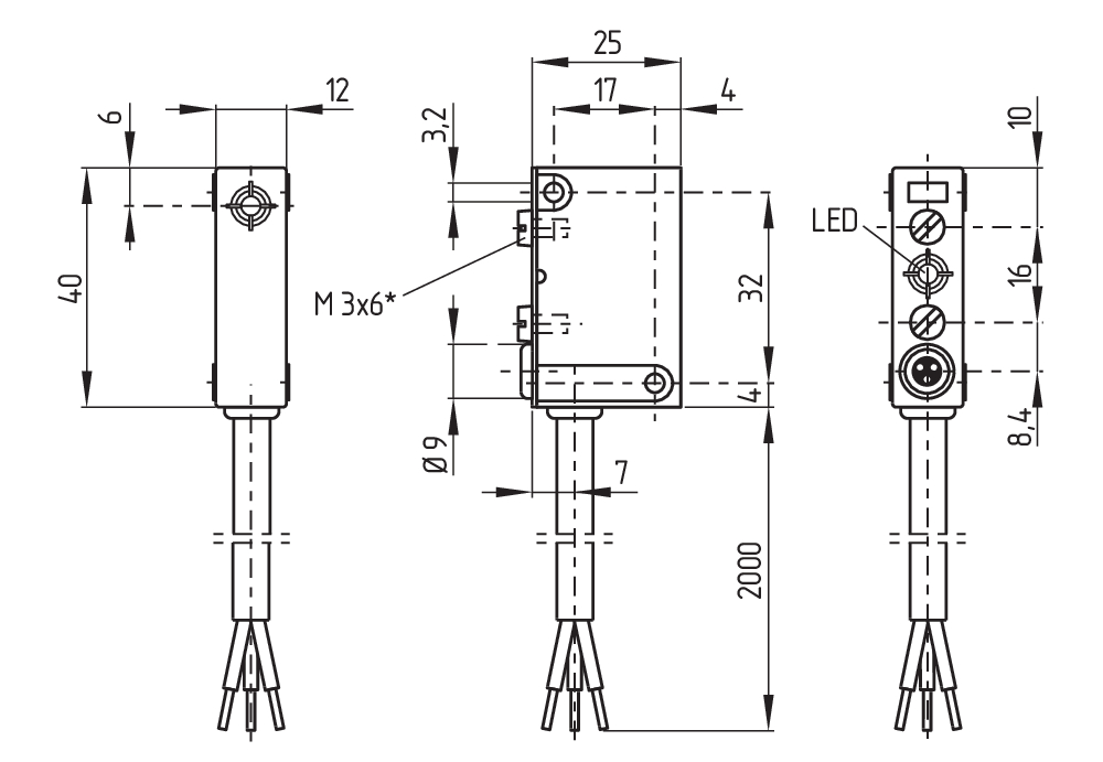
| 250 | Square design, 40 x 25 x 12 mm |
| (3) | |
| 01 | Opener (NC) |
| 10 | Normally open contact (NO) |
| 10/01 | NO contact / NC contact with wiring compartment |
| 11 | 1 NO contact / 1 NC contact antivalent |
| (4) | |
| without | Cable |
| D | DC 2-wire |
| (5) | |
| N | n-type |
| P | p-type |
| (6) | |
| 1716 | cable entries from sides |
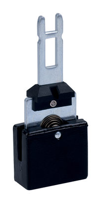
- Design 250
Ordering data
| Product type description |
IFL 4-250-10P 6,0M |
| Article number (order number) |
101093061 |
| eCl@ss number, version 12.0 |
27-27-40-01 |
| eCl@ss number, version 11.0 |
27-27-01-01 |
| eCl@ss number, version 9.0 |
27-27-01-01 |
| ETIM number, version 7.0 |
EC002714 |
| ETIM number, version 6.0 |
EC002714 |
General data
| Standards |
DIN VDE 0660-208 EN IEC 60947-5-2 |
| Housing construction form |
Block |
| Installation conditions (mechanical) |
not flush |
| Housing material |
Plastic |
| Active area |
Plastic |
| Gross weight |
230 g |
General data - Features
| Integral system diagnostics, status |
Yes |
| Cable sleeve |
No |
| Number of cable wires |
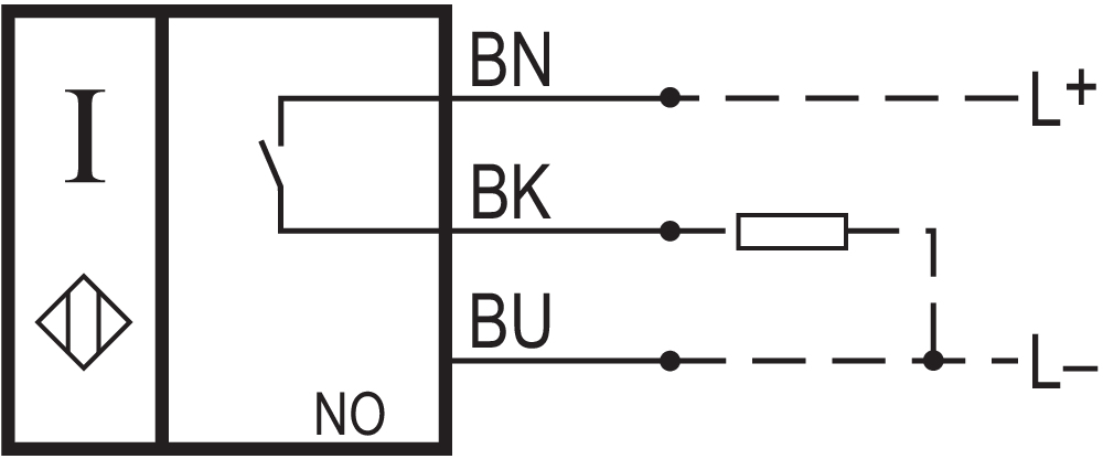
3 |
Mechanical data - Switching distances
| Nominal switching distance Sn |
4 mm |
| Note (switching distance) |
All switching distances in accordance EN IEC 60947-5-2 |
Mechanical data - Connection technique
| Length of cable |
6 m |
| Termination |
Cable |
| Number of cable wires |
3 |
| Wire cross-section |
0.34 mm2 |
| Material of the Cable mantle |
PVC |
Mechanical data - Dimensions
| Length of sensor |
12 mm |
| Width of sensor |
40 mm |
| Height of sensor |
25 mm |
Ambient conditions
| Degree of protection |
IP67 |
| Ambient temperature |
-25 ... +70 °C |
| Resistance to vibrations |
10 … 55 Hz, amplitude 1 mm |
| Restistance to shock |
30 g / 11 ms |
| Protection class |
II |
Electrical data
| Operating voltage |
10 ... 30 VDC |
| Type of voltage range |
DC |
| No-load supply current I0, typical |
3 mA |
| Rated operating voltage |
10 ... 30 VDC |
| Operating current |
200 mA |
| Switching element |
Normally open contact (NO) |
| Protection circuit integrated |
inductive interference protection Protection against polarity reversal Surge protection Max. fuse rating |
| Switching frequency, approx. |
1,000 Hz |
Electrical data - Digital Output
| Voltage drop Ud, maximum |
1.2 V |
| Current at Voltage drop Ud |
0.2 A |
| Design of control elements |
p-type |
Status indication
| Note (Integral System Diagnostics, status ) |
yellow LED |
Scope of delivery
| Scope of delivery of mounting material |
with 2 M3x6 screws for rear mounting |
Note
| Note (General) |
Switches can be mounted adjacent to each other without interference. |
Language filter
Datasheet
Operating instructions (supplementary sheet/quick guide)
EC Declaration of conformity
Download the latest version of Adobe Reader
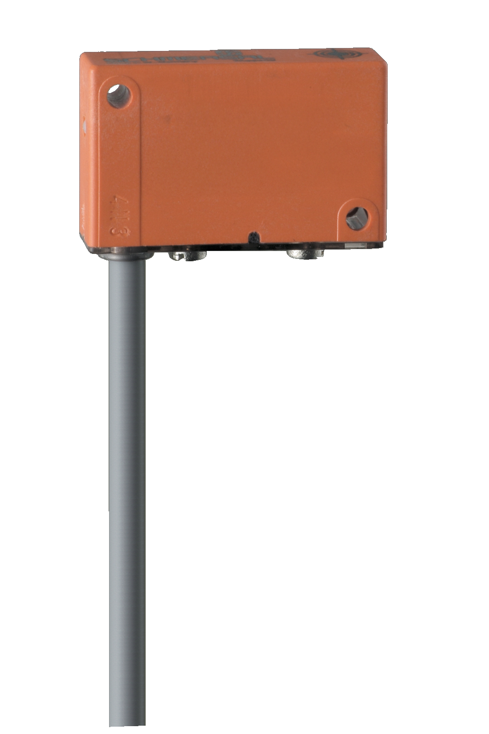
Product picture (catalogue individual photo)
Dimensional drawing basic component
Schmersal Canada Ltd., 29 Centennial Road, Unit 1, Orangeville, Ontario L9W 1R1 Canada
The details and data referred to have been carefully checked. Images may diverge from original. Further technical data can be found in the manual. Technical amendments and errors possible.
Generated on: 2025-10-16, 12:56 p.m.
Recently viewed
BP 11 S
M 630-11-5-C-E40