AZ 17-11ZRI-ST B1

AZ 17-11ZRI-ST B1
| Product type description: AZ 17-(1)Z(2)I-(3)-(4)-(5) |
| (1) | |
| 11 | 1 NO contact/1 NC contact |
| 02 | 2 NC contact |
| (2) | |
| without | Latching force 5 N |
| R | Latching force 30 N |
| (3) | |
| without | M16 cable gland |
| ST | M12 connector |
| (4) | |
| B1 | Actuator B1 |
| B5 | Actuator B5 |
| B6L | Actuator B6L |
| B6R | Actuator B6R |
| (5) | |
| 1637 | Gold-plated contacts |
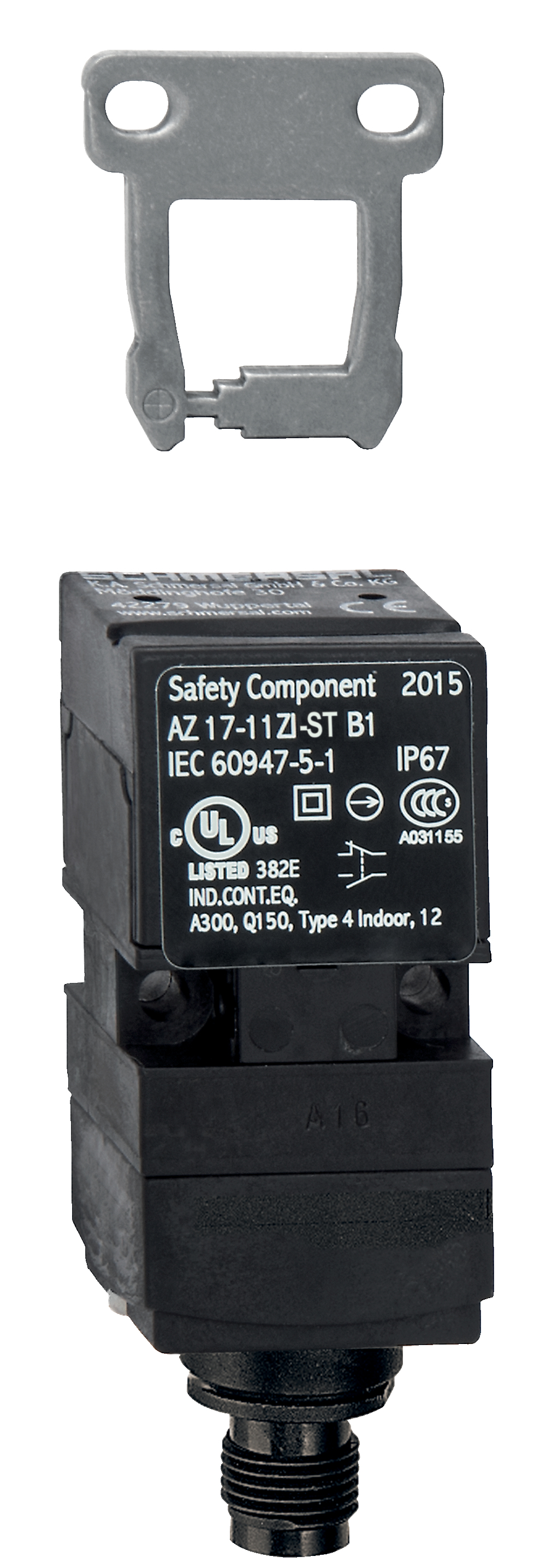
- Connector M12 x 1, 4-pole
- Thermoplastic enclosure
- Double-insulated
- Long life
- 30 mm x 60 mm x 30 mm
- Particularly suitable for sliding doors
- small body
- Individual coding
- Coding level "High" according to ISO 14119
- High level of contact reliability with low voltages and currents
- Insensitive to soiling
- Slot sealing plug included
- 8 actuating planes
Ordering data
| Product type description |
AZ 17-11ZRI-ST B1 |
| Article number (order number) |
101144077 |
| eCl@ss number, version 12.0 |
27-27-26-02 |
| eCl@ss number, version 11.0 |
27-27-26-02 |
| eCl@ss number, version 9.0 |
27-27-26-02 |
| ETIM number, version 7.0 |
EC002592 |
| ETIM number, version 6.0 |
EC002592 |
Approvals - Standards
| Certificates |
cULus |
General data
| Standards |
EN ISO 13849-1 EN ISO 14119 EN IEC 60947-5-1 |
| Coding level according to EN ISO 14119 |
High |
| Working principle |
electromechanical |
| Housing material |
Plastic, glass-fibre reinforced thermoplastic, self-extinguishing |
| Material of the actuator |
Stainless steel |
| Gross weight |
86 g |
General data - Features
| Increased latching force |
Yes |
| Number of actuating directions |
2 |
| Number of auxiliary contacts |
1 |
| Number of safety contacts |
1 |
| Number of cable glands |
1 |
| Safety classification |
| Standards |
EN ISO 13849-1 |
| Performance Level, up to |
c |
| Category |
1 |
| B10D Normally-closed contact (NC) |
2,000,000 Operations |
| Note |
Electrical life on request. |
| B10D Normally-open contact (NO) |
1,000,000 Operations |
| Note |
at 10% Ie and ohmic load |
| Mission time |
20 Year(s) |
| Safety classification - Fault exclusion |
| Please note: |
Can be used when fault exclusion for dangerous damage to the 1-channel mechanism is permissible and sufficient protection against manipulation is guaranteed. |
| Performance Level, up to |
d |
| Category |
3 |
| Note |
for 2-channel use and with suitable logic unit. |
| Mission time |
20 Year(s) |
Mechanical data
| Mechanical lifetime, minimum |
1,000,000 Operations |
| Latching force |
30 N |
| Positive break travel |
11 mm |
| Positive break force per NC contact, minimum |
17 N |
| Actuating speed, maximum |
2 m/s |
| Mounting |
Screws |
| Type of the fixing screws |
2x M4 |
Mechanical data - Connection technique
| Termination |
Connector plug M12, 4-pole, (A-coding) |
Mechanical data - Dimensions
| Length of sensor |
30 mm |
| Width of sensor |
30 mm |
| Height of sensor |
85 mm |
Ambient conditions
| Degree of protection |
IP67 |
| Ambient temperature |
-30 ... +80 °C |
| Storage and transport temperature |
-30 ... +85 °C |
| Permissible installation altitude above sea level, maximum |
2,000 m |
Ambient conditions - Insulation values
| Rated insulation voltage Ui |
250 VAC |
| Rated impulse withstand voltage Uimp |
4 kV |
| Overvoltage category |
III |
| Degree of pollution |
3 |
Electrical data
| Thermal test current |
10 A |
| Required rated short-circuit current |
1,000 A |
| Switching element |
1 NO contact, 1 NC contacts |
| Note (Switching element) |
with double break |
| Switching principle |
slow action, positive break NC contact |
| Maximale Schalthäufigkeit |
2,000 /h |
| Material of the contacts, electrical |
Silver |
Electrical data - Safety contacts
| Voltage, Utilisation category AC-15 |
230 VAC |
| Current, Utilisation category AC-15 |
4 A |
| Voltage, Utilisation category DC-13 |
24 VDC |
| Current, Utilisation category DC-13 |
4 A |
Electrical data - Auxiliary contacts
| Voltage, Utilisation category AC-15 |
230 VAC |
| Current, Utilisation category AC-15 |
4 A |
| Voltage, Utilisation category DC-13 |
24 VDC |
| Current, Utilisation category DC-13 |
4 A |
Scope of delivery
| Scope of delivery |
Slot cover for dust-proof covering of the opening not in use |
Note
| Note (General) |
This type termination (IDC) method enables simple connetion of flexible conductors without the need for the use of conductor ferrules The axis of the hinge must be 10 mm above and in a parallel plane to the top surface of the safety switch. minimum actuating radius on rotating guard systems via the narrow edge of the actuator 140 mm minimum actuating radius on hinged guards in line with the plane of the actuator 200 mm The actuator is not available separately. |
Language filter
Datasheet
Operating instructions and Declaration of conformity
UL Certificate
Brochure
SISTEMA-VDMA library
Download the latest version of Adobe Reader
Product picture (catalogue individual photo)
ID: kaz17f31
| 1.1 MB | .jpg | 352.778 x 1012.472 mm - 1000 x 2870 px - 72 dpi
| 120.5 kB | .png | 74.083 x 212.372 mm - 210 x 602 px - 72 dpi
| 27.0 kB | .jpg | 43.039 x 123.472 mm - 122 x 350 px - 72 dpi
| 964.3 kB | .jpg | 352.778 x 1012.472 mm - 1000 x 2870 px - 72 dpi
| 121.1 kB | .png | 74.083 x 212.372 mm - 210 x 602 px - 72 dpi
| 57.8 kB | .png | 43.039 x 123.472 mm - 122 x 350 px - 72 dpi
Dimensional drawing basic component
Dimensional drawing actuator
Switch travel diagram

Diagram
Contact arrangement
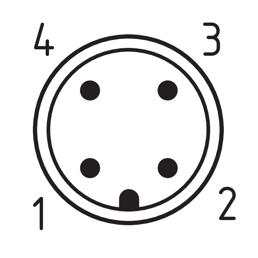
Table of Contents
- 1 About this document
- 1.1 Function
- 1.2 Target group of the operating instructions: authorised qualified personnel
- 1.3 Explanation of the symbols used
- 1.4 Appropriate use
- 1.5 General safety instructions
- 2 Product description
- 2.1 Ordering code
- 2.2 Special versions
- 2.3 Purpose
- 2.4 Warning about misuse
- 2.5 Exclusion of liability
- 2.6 Technical Data
- 3 Mounting
- 3.1 General mounting instructions
- 3.2 Mounting of the actuator
- 3.3 Dimensions
- 4 Electrical connection
- 4.1 General information for electrical connection
- 4.2 Contact Options
- 5 Set-up and maintenance
- 6 Disassembly and disposal
- 6.1 Disassembly
- 6.2 Disposal
1 About this document
1.1 Function
This document provides all the information you need for the mounting, set-up and commissioning to ensure the safe operation and disassembly of the switchgear. The operating instructions enclosed with the device must always be kept in a legible condition and accessible.
1.2 Target group of the operating instructions: authorised qualified personnel
All operations described in the operating instructions manual must be carried out by trained specialist personnel, authorised by the plant operator only.
Please make sure that you have read and understood these operating instructions and that you know all applicable legislations regarding occupational safety and accident prevention prior to installation and putting the component into operation.
The machine builder must carefully select the harmonised standards to be complied with as well as other technical specifications for the selection, mounting and integration of the components.
The information contained in this operating instructions manual is provided without liability and is subject to technical modifications.
1.3 Explanation of the symbols used
- Information, hint, note: This symbol is used for identifying useful additional information.
- Caution: Failure to comply with this warning notice could lead to failures or malfunctions.
Warning: Failure to comply with this warning notice could lead to physical injury and/or damage to the machine.
1.4 Appropriate use
The Schmersal range of products is not intended for private consumers.
The products described in these operating instructions are developed to execute safety-related functions as part of an entire plant or machine. It is the responsibility of the manufacturer of a machine or plant to ensure the correct functionality of the entire machine or plant.
The safety switchgear must be exclusively used in accordance with the versions listed below or for the applications authorised by the manufacturer. Detailed information regarding the range of applications can be found in the chapter "Product description".
1.5 General safety instructions
The user must observe the safety instructions in this operating instructions manual, the country specific installation standards as well as all prevailing safety regulations and accident prevention rules.
- Further technical information can be found in the Schmersal catalogues or in the online catalogue on the Internet: products.schmersal.com.
2 Product description
2.1 Ordering code
| Product type description: AZ 17-(1)Z(2)I-(3)-(4)-(5) |
| (1) | |
| 11 | 1 NO contact/1 NC contact |
| 02 | 2 NC contact |
| (2) | |
| without | Latching force 5 N |
| R | Latching force 30 N |
| (3) | |
| without | M16 cable gland |
| ST | M12 connector |
| (4) | |
| B1 | Actuator B1 |
| B5 | Actuator B5 |
| B6L | Actuator B6L |
| B6R | Actuator B6R |
| (5) | |
| 1637 | Gold-plated contacts |
2.2 Special versions
For special versions, which are not listed in the ordering code, these specifications apply accordingly, provided that they correspond to the standard version.
2.3 Purpose
The safety switches with separate actuator are suitable for sliding, hinged and removable safety guards, which need to be closed in order to ensure the necessary operational safety.
The safety switches are used for applications, in which the hazardous situation is terminated without delay when the safety guard is opened.
When the safety guard is opened, the NC contacts are positively opened and the NO contacts are closed.
- The safety switchgear units are classified as type 2 interlocking devices in accordance with EN ISO 14119 and are rated as highly coded.
- The user must evaluate and design the safety chain in accordance with the relevant standards and the required safety level.
- The entire concept of the control system, in which the safety component is integrated, must be validated to the relevant standards.
2.4 Warning about misuse
- In case of improper use or manipulation of the safety switchgear, personal hazards or damages to machinery or plant components cannot be excluded. There are no residual risks, provided that the safety instructions as well as the instructions regarding mounting, commissioning, operation and maintenance are observed.
2.5 Exclusion of liability
We shall accept no liability for damages and malfunctions resulting from defective mounting or failure to comply with the operating instructions manual. The manufacturer shall accept no liability for damages resulting from the use of unauthorised spare parts or accessories.
For safety reasons, invasive work on the device as well as arbitrary repairs, conversions and modifications to the device are strictly forbidden, the manufacturer shall accept no liability for damages resulting from such invasive work, arbitrary repairs, conversions and/or modifications to the device.
2.6 Technical Data
Approvals - Standards
| Certificates |
cULus |
General data
| Standards |
EN ISO 13849-1 EN ISO 14119 EN IEC 60947-5-1 |
| Coding level according to EN ISO 14119 |
High |
| Working principle |
electromechanical |
| Housing material |
Plastic, glass-fibre reinforced thermoplastic, self-extinguishing |
| Material of the actuator |
Stainless steel |
| Gross weight |
86 g |
General data - Features
| Increased latching force |
Yes |
| Number of actuating directions |
2 |
| Number of auxiliary contacts |
1 |
| Number of safety contacts |
1 |
| Number of cable glands |
1 |
| Safety classification |
| Standards |
EN ISO 13849-1 |
| Performance Level, up to |
c |
| Category |
1 |
| B10D Normally-closed contact (NC) |
2,000,000 Operations |
| Note |
Electrical life on request. |
| B10D Normally-open contact (NO) |
1,000,000 Operations |
| Note |
at 10% Ie and ohmic load |
| Mission time |
20 Year(s) |
| Safety classification - Fault exclusion |
| Please note: |
Can be used when fault exclusion for dangerous damage to the 1-channel mechanism is permissible and sufficient protection against manipulation is guaranteed. |
| Performance Level, up to |
d |
| Category |
3 |
| Note |
for 2-channel use and with suitable logic unit. |
| Mission time |
20 Year(s) |
Mechanical data
| Mechanical lifetime, minimum |
1,000,000 Operations |
| Latching force |
30 N |
| Positive break travel |
11 mm |
| Positive break force per NC contact, minimum |
17 N |
| Actuating speed, maximum |
2 m/s |
| Mounting |
Screws |
| Type of the fixing screws |
2x M4 |
Mechanical data - Connection technique
| Termination |
Connector plug M12, 4-pole, (A-coding) |
Mechanical data - Dimensions
| Length of sensor |
30 mm |
| Width of sensor |
30 mm |
| Height of sensor |
85 mm |
Ambient conditions
| Degree of protection |
IP67 |
| Ambient temperature |
-30 ... +80 °C |
| Storage and transport temperature |
-30 ... +85 °C |
| Permissible installation altitude above sea level, maximum |
2,000 m |
Ambient conditions - Insulation values
| Rated insulation voltage Ui |
250 VAC |
| Rated impulse withstand voltage Uimp |
4 kV |
| Overvoltage category |
III |
| Degree of pollution |
3 |
Electrical data
| Thermal test current |
10 A |
| Required rated short-circuit current |
1,000 A |
| Switching element |
1 NO contact, 1 NC contacts |
| Note (Switching element) |
with double break |
| Switching principle |
slow action, positive break NC contact |
| Maximale Schalthäufigkeit |
2,000 /h |
| Material of the contacts, electrical |
Silver |
Electrical data - Safety contacts
| Voltage, Utilisation category AC-15 |
230 VAC |
| Current, Utilisation category AC-15 |
4 A |
| Voltage, Utilisation category DC-13 |
24 VDC |
| Current, Utilisation category DC-13 |
4 A |
Electrical data - Auxiliary contacts
| Voltage, Utilisation category AC-15 |
230 VAC |
| Current, Utilisation category AC-15 |
4 A |
| Voltage, Utilisation category DC-13 |
24 VDC |
| Current, Utilisation category DC-13 |
4 A |
Note about the safety classification
Basically suitable up to Cat. 1 / PL c.
With 2-channel usage with fault exclusion mechanism (if a fault exclusion to the 1-channel mechanics is authorised) and suitable logic applicable up to Cat. 3 / PL d
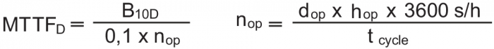
(Determined values can vary depending on the application-specific parameters hop, dop and tcycle as well as the load.)
If multiple safety components are wired in series, the Performance Level to EN ISO 13849-1 will be reduced due to the restricted error detection under certain circumstances.
3 Mounting
3.1 General mounting instructions
- Please observe the remarks of the standards EN ISO 12100, EN ISO 14119 and EN ISO 14120.
3.2 Mounting of the actuator
- The marks on the used actuator opening of the solenoid interlock and on the actuator must be opposite.
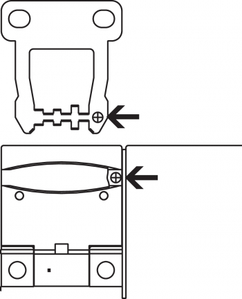
- The actuator must be permanently fitted to the safety guards and protected against displacement by suitable measures (tamperproof screws, gluing, drilling of the screw heads).
Please observe that, when fixing the switch e.g. by means of rivetting or welding, the insertion depth of the actuator is not modified. Different actuator forms are available. The actuators B1 and B5 are preferably used for sliding and removable safety guards. For hinged guards, the B6R and B6L actuators.
Actuator B6L / B6R
When the switch is fitted on a hinged safety guard, please ensure that the point of rotation is located within the range of the upper surface of the safety switch, in which the actuator hook is inserted (refer to table).
| Actuating radii [mm] | 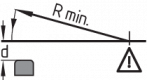 |  | ||
|---|---|---|---|---|
| over the small edge of the actuator | over the wide edge of the actuator | |||
| Rmin | d | Rmin | d | |
| B6L | 50 | 11 | 50 | 11 |
| B6R | 50 | 11 | 50 | 11 |
The axis of the hinge must be d mm above and in a parallel plane to the top surface of the safety switch. The basis setting provides a minimum radius of Rmin.
The B6L or B6R actuators are set to the smallest radius in factory. To increase the radius, the setting screws a + b must be turned by means of a hexagonal key A/F 2.0 mm.

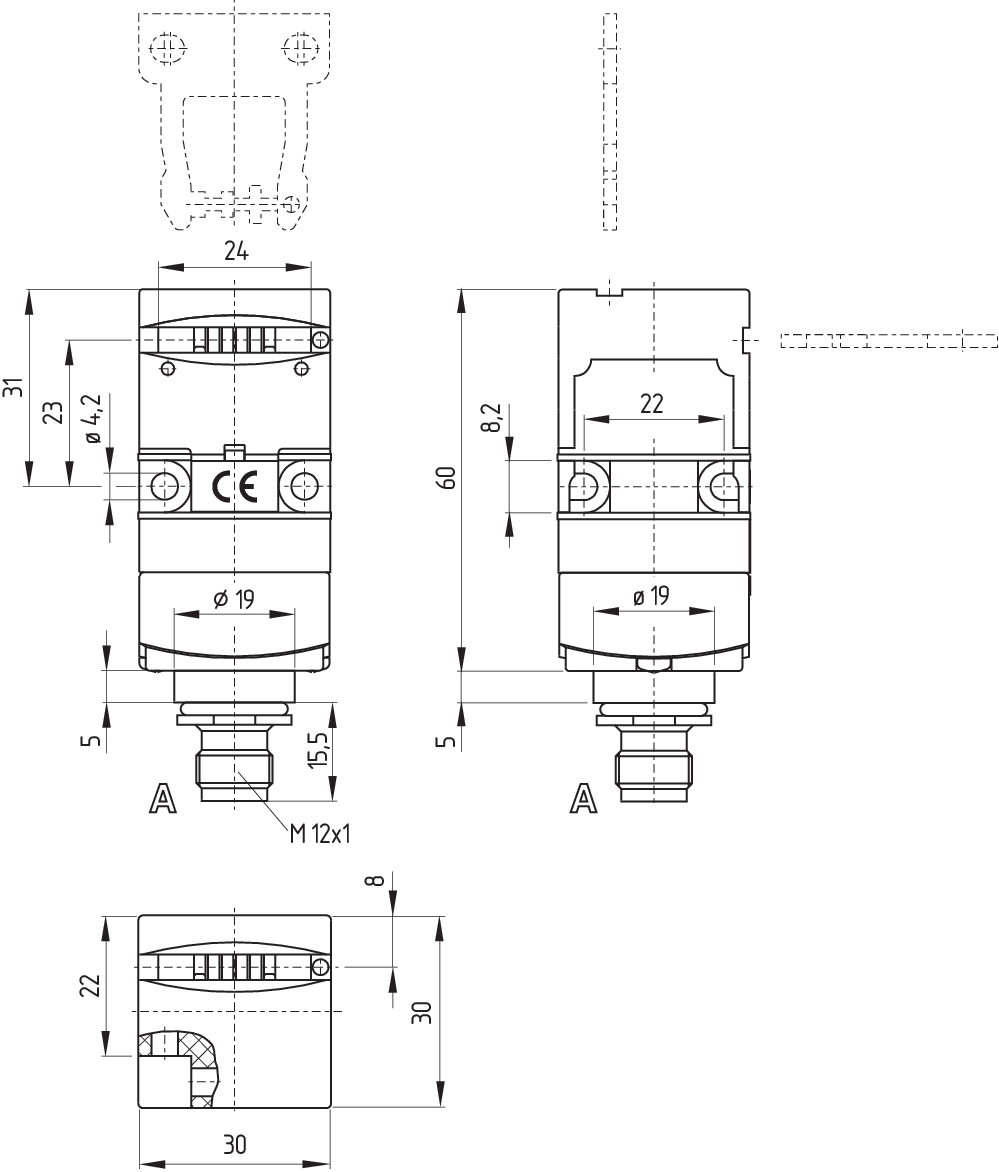
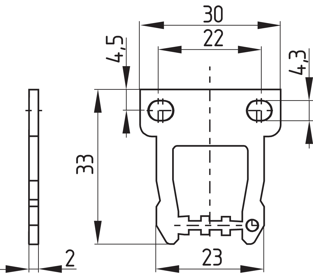
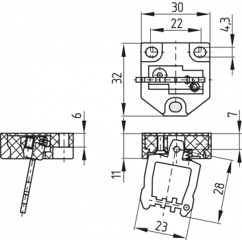
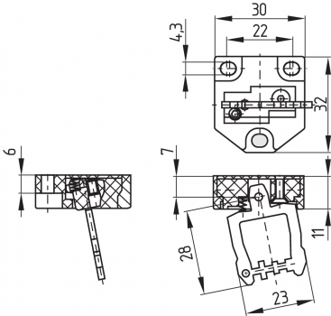
3.3 Dimensions
All measurements in mm.
AZ 17 safety switch

Actuator
| Straight actuator B1 | Angled actuator B5 |
|---|---|
 |  |
| Flexible actuator B6L | Flexible actuator B6R |
|---|---|
 |  |
4 Electrical connection
4.1 General information for electrical connection
- The electrical connection may only be carried out by authorised personnel in a de-energised condition.
The contact labelling can be found in the wiring compartment of the switch. Appropriate cable glands with a suitable degree of protection are to be used.
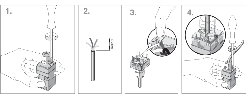
IDC method of termination
The IDC method of termination (cut clamp technology) enables connecting flexible wires with cable section 0.75 … 1 mm² without using conductor ferrules. To this effect, strip the wire for 17 ... 20 mm and insert it into the cable gland, close the cable gland, push the conductors in the groove of the cover (refer to wiring example) and screw the cover back. Alternatingly tighten the cover screws uniformly. Tightening force for the Torx T10 cover screws 0.7 ... 1 Nm.
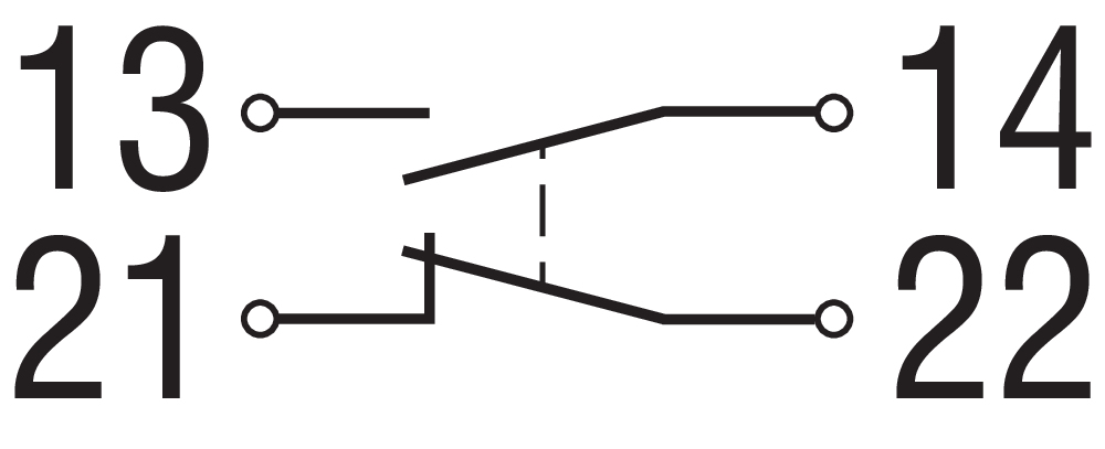
4.2 Contact Options
Contacts are shown with safety guard closed. All NC contacts have positive break B.
| AZ 17-11Z.I | AZ 17-02Z.I |
|---|---|
 |  |
with connector, A-coding
| AZ 17-11Z.I-ST | AZ 17-02Z.I-ST |
|---|---|
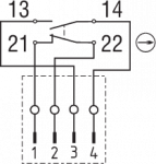 | 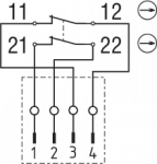 |
| Key | |
|---|---|
| B | Automatic opener, NC contact |
 | Normally-open contact |
 | Normally-closed contact |
5 Set-up and maintenance
The safety function of the safety components must be tested. In the case of correct installation and adequate use, the safety switchgear features maintenance-free functionality. A regular visual inspection and functional test, including the following steps, is recommended:
- Check for correct installation of the actuator and the switch
- Check the integrity of the cable entry and connections
- Check the switch enclosure for damages
- Remove particles of dust and soiling
- Adequate measures must be taken to ensure protection against tampering either to prevent tampering of the safety guard, for instance by means of replacement actuators.
- Damaged or defective components must be replaced.
6 Disassembly and disposal
6.1 Disassembly
The safety switchgear must be disassembled in a de-energised condition only.
6.2 Disposal
- The safety switchgear must be disposed of in an appropriate manner in accordance with the national prescriptions and legislations.
| EU Declaration of Conformity |  |
| Original | K.A. Schmersal GmbH & Co. KG Möddinghofe 30 42279 Wuppertal Germany Internet: www.schmersal.com |
| Declaration: | We hereby certify that the hereafter described components both in their basic design and construction conform to the applicable European Directives. |
| Name of the component: | AZ 17 I |
| Type: | See ordering code |
| Description of the component: | Positive break position switch with separate actuator for safety functions |
| Relevant Directives: | Machinery Directive | 2006/42/EC |
| RoHS-Directive | 2011/65/EU |
| Applied standards: | EN 60947-5-1:2017 EN ISO 14119:2013 |
| Person authorised for the compilation of the technical documentation: | Oliver Wacker Möddinghofe 30 42279 Wuppertal |
| Place and date of issue: | Wuppertal, August 3, 2020 |
 |
| Authorised signature Philip Schmersal Managing Director |
| UK Declaration of Conformity | |
| Company: | K.A. Schmersal GmbH & Co. KG Möddinghofe 30 42279 Wuppertal Germany Internet: www.schmersal.com |
| Declaration: | We hereby, under sole responsibility, certify that the hereafter described components both in their basic design and construction conform to the relevant statutory requirements, regulations and designated standards of the United Kingdom. |
| Name of the component: | AZ 17 I |
| Type: | See ordering code |
| Description of the component: | Positive break position switch with separate actuator for safety functions |
| Relevant legislation: | Supply of Machinery (Safety) Regulations The Restriction of the Use of Certain Hazardous Substances in Electrical and Electronic Equipment Regulations | 2008 2012 |
| Designated standards: | EN 60947-5-1:2017 EN ISO 14119:2013 |
| UK-Importer / Person authorised for the compilation of the technical documentation: | Schmersal UK Ltd. Paul Kenney Unit 1, Sparrowhawk Close Enigma Business Park Malvern, Worcestershire, WR14 1GL |
| Place and date of issue: | Wuppertal, June 17, 2022 |
|
| Authorised signature Philip Schmersal Managing Director |
Schmersal India Pvt. Ltd., Plot No - G-7/1, Ranjangaon MIDC, Tal. - Shirur, Dist.- Pune 412 220
The details and data referred to have been carefully checked. Images may diverge from original. Further technical data can be found in the manual. Technical amendments and errors possible.
Generated on: 12/09/2025, 10:00 am