AZS 2305.1 110 VAC
AZS 2305.1 110 VAC
Downloads
- Fail-safe delay timer
- Time adjustable from 0,1 s to 99 min
- 3 safety contacts
- 2 Signalling outputs
Ordering data
| Note (Delivery capacity) |
Not available! |
| Product type description |
AZS 2305.1 110 VAC |
| Article number (order number) |
101126704 |
| EAN (European Article Number) |
4030661058993 |
| eCl@ss number, version 12.0 |
27-37-18-19 |
| eCl@ss number, version 11.0 |
27-37-18-19 |
| eCl@ss number, version 9.0 |
27-37-18-19 |
| ETIM number, version 7.0 |
EC001449 |
| ETIM number, version 6.0 |
EC001449 |
Approvals - Standards
| Certificates |
cULus |
General data
| Standards |
BG-GS-ET-20 EN IEC 62061 EN ISO 13849-1 EN IEC 60947-5-1 EN IEC 60947-5-3 EN IEC 60947-5-5 EN IEC 60204-1 EN IEC 60947-1 |
| Housing material |
Glass-fibre, reinforced thermoplastic |
| Gross weight |
445 g |
General data - Features
| Wire breakage detection |
Yes |
| Cross-circuit detection |
Yes |
| Automatic reset function |
Yes |
| Reset after disconnection of supply voltage |
Yes |
| Earth connection detection |
Yes |
| Integral system diagnostics, status |
Yes |
| Number of LEDs |
1 |
| Number of normally closed (NC) |
1 |
| Number of normally open (NO) |
1 |
| Number of undelayed semi-conductor outputs with signaling function |
2 |
| Number of safety contacts |
3 |
| Number of signalling outputs |
2 |
| Safety classification |
| Vorschriften |
EN IEC 61508 |
| Performance Level, up to |
d |
| Category |
3 |
| PFH value |
1.00 x 10⁻⁷ /h |
| Safety Integrity Level (SIL), suitable for applications in |
2 |
| Mission time |
20 Year(s) |
Mechanical data
| Mounting |
Snaps onto standard DIN rail to EN 60715 |
Mechanical data - Connection technique
| Termination |
rigid or flexible Screw terminals M20 x 1.5 |
| Cable section, maximum |
4 mm² |
| Note |
All indications including the conductor ferrules. |
| Tightening torque of Clips |
0.4 Nm |
Mechanical data - Dimensions
| Width |
55 mm |
| Height |
75 mm |
| Depth |
110 mm |
Ambient conditions
| Degree of protection of the enclosure |
IP40 |
| Degree of protection of the mounting space |
IP54 |
| Degree of protection of clips or terminals |
IP20 |
| Ambient temperature |
+0 ... +55 °C |
| Storage and transport temperature |
-25 ... +70 °C |
| Resistance to vibrations |
10 ... 55 Hz, Amplitude 0.35 mm |
| Restistance to shock |
30 g / 11 ms |
Ambient conditions - Insulation values
| Rated impulse withstand voltage Uimp |
4 kV |
| Overvoltage category |
III |
| Degree of pollution |
2 |
Electrical data
| Frequency range |
50 Hz 60 Hz |
| Operating voltage |
110 VAC -15 % / +15 % |
| Rated operating voltage |
110 VAC |
| Rated AC voltage for controls, 50 Hz, minimum |
20.4 VAC |
| Rated control voltage at AC 50 Hz, maximum |
26.4 VAC |
| Rated AC voltage for controls, 60 Hz, minimum |
20.4 VAC |
| Rated control voltage at AC 60 Hz, maximum |
26.4 VAC |
| Electrical power consumption |
5 W |
| Contact resistance, maximum |
0.1 Ω |
| Note (Contact resistance) |
in new state |
| Drop-out delay in case of power failure, typically |
80 ms |
| Drop-out delay in case of emergency, typically |
20 ms |
| Pull-in delay at automatic start, maximum, typically |
100 ms |
| Pull-in delay at RESET, typically |
20 ms |
Electrical data - Safe relay outputs
| Voltage, Utilisation category AC-15 |
250 VAC |
| Current, Utilisation category AC-15 |
2 A |
| Voltage, Utilisation category DC-13 |
24 VDC |
| Current, Utilisation category DC-13 |
2 A |
| Switching capacity, minimum |
10 VDC |
| Switching capacity, minimum |
10 mA |
| Switching capacity, maximum |
250 VAC |
| Switching capacity, maximum |
8 A |
Electrical data - Digital inputs
| Input signal, HIGH Signal "1" |
10 … 30 VDC |
| Input signal, LOW Signal "0" |
0 … 2 VDC |
| Conduction resistance, maximum |
40 Ω |
Electrical data - Digital Output
| Voltage, Utilisation category DC-12 |
24 VDC |
| Current, Utilisation category DC-12 |
0.1 A |
Electrical data - Relay outputs (auxiliary contacts)
| Switching capacity, maximum |
24 VDC |
| Switching capacity, maximum |
2 A |
Electrical data - Electromagnetic compatibility (EMC)
| EMC rating |
EMC-Directive |
Integral system diagnosis (ISD)
| Note (ISD -Faults) |
The following faults are registered by the safety monitoring modules and indicated by ISD. |
| Faults |
Failure of the safety relay to pull-in or drop-out Fault on the input circuits or the relay control circuits of the safety monitoring module Difference in time setting between channel I and channel II Cross conclusions to the input lines Interruption of the input connections |
Other data
| Note (applications) |
Fail-safe delay timer |
Note
| Note (General) |
Inductive loads (e.g. contactors, relays, etc.) are to be suppressed by means of a suitable circuit. |
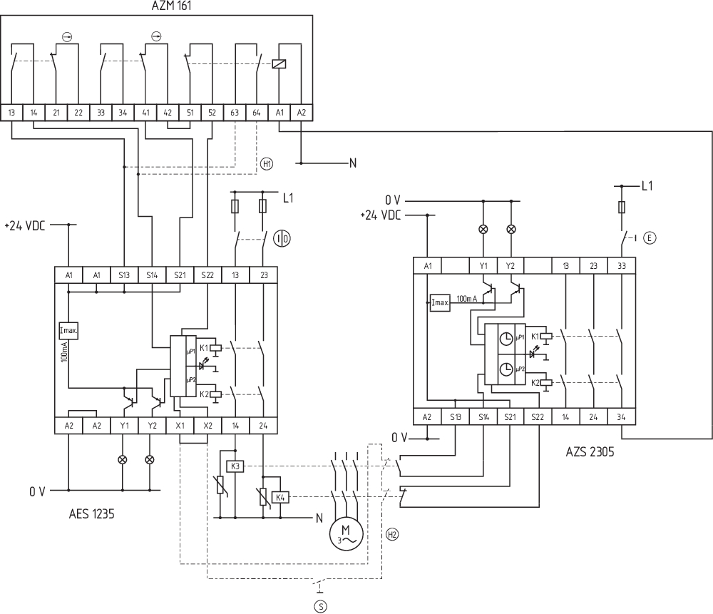
Wiring example
| Note (Wiring diagram) |
The wiring diagram is shown with guard doors closed and in de-energised condition. The ISD tables (Intergral System Diagnostics) for analysis of the fault indications and their causes are shown in the appendix. To monitor one guard door at plants with dangerous run-on movements up to PL d and Category 3 Monitoring time for unlocking of solenoid interlocks The solenoid interlock releases the guard device only when the set time has elapsed. The time begins to run when the power contactors have dropped out. |
Language filter
Datasheet
Operating instructions and Declaration of conformity
UL Certificate
Wiring example (electr. wiring)
Force-travel diagram
Download the latest version of Adobe Reader
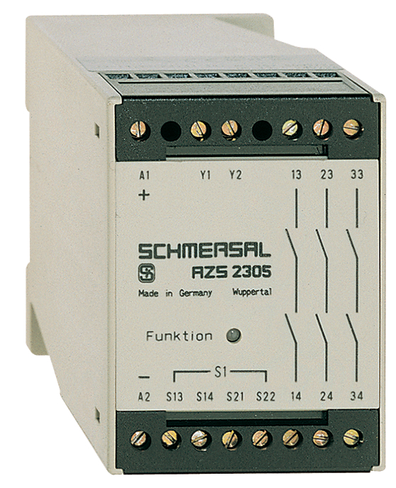
Product picture (catalogue individual photo)
Wiring example
| EU Declaration of Conformity |  |
| Original | K.A. Schmersal GmbH & Co. KG Möddinghofe 30 42279 Wuppertal Germany Internet: www.schmersal.com |
| Declaration: | We hereby certify that the hereafter described components both in their basic design and construction conform to the applicable European Directives. |
| Name of the component: | AZS 2305 |
| Type: | See ordering code |
| Description of the component: | Fail-safe delay timer |
| Relevant Directives: | Machinery Directive | 2006/42/EC |
| EMC-Directive | 2014/30/EU | |
| RoHS-Directive | 2011/65/EU |
| Applied standards: | EN ISO 13849-1:2008 + AC:2009 EN 61508 parts 1-7:2010 EN 62061:2005 + AC:2010 + A1:2013 |
| Notified body for Type Examination: | TÜV Rheinland Industrie Service GmbH Alboinstraße 56, 12103 Berlin ID n°: 0035 |
| EC-Type Examination Certificate: | 01/205/0715.01/15 |
| Person authorised for the compilation of the technical documentation: | Oliver Wacker Möddinghofe 30 42279 Wuppertal |
| Place and date of issue: | Wuppertal, June 8, 2017 |
 |
| Authorised signature Philip Schmersal Managing Director |
Schmersal India Pvt. Ltd., Plot No - G-7/1, Ranjangaon MIDC, Tal. - Shirur, Dist.- Pune 412 220
The details and data referred to have been carefully checked. Images may diverge from original. Further technical data can be found in the manual. Technical amendments and errors possible.
Generated on: 18/03/2025, 9:34 pm