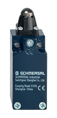
AZ315-T12

AZ315-T12
- Design to EN 50041
- Metal enclosure
- Actuator heads can be repositioned in steps 4 x 90°
- Different contact options
- Latching force 12N or 30N depending on variant
Ordering data
| Product type description |
AZ315-T12 |
| Article number (order number) |
103049880 |
| EAN (European Article Number) |
4030661625492 |
| eCl@ss number, version 12.0 |
27-27-06-10 |
| eCl@ss number, version 11.0 |
27-27-06-10 |
| eCl@ss number, version 9.0 |
27-27-06-10 |
| ETIM number, version 7.0 |
EC002592 |
| ETIM number, version 6.0 |
EC002592 |
Approvals - Standards
| Certificates |
cULus CCC |
General data
| Standards |
EN ISO 13849-1 EN ISO 14119 EN IEC 60947-5-1 |
| Coding level according to EN ISO 14119 |
Low |
| Working principle |
electromechanical |
| Housing material |
Metal, zinc die-cast |
| Housing coating material |
painted |
| Gross weight |
421 g |
General data - Features
| Number of auxiliary contacts |
1 |
| Number of safety contacts |
2 |
| Number of cable glands |
1 |
| Safety classification |
| Standards |
EN ISO 13849-1 |
| Performance Level, up to |
c |
| Category |
1 |
| B10D Normally-closed contact (NC) |
2,000,000 Operations |
| B10D Normally-open contact (NO) |
1,000,000 Operations |
| Note |
at 10% Ie and ohmic load |
| Mission time |
20 Year(s) |
| Safety classification - Fault exclusion |
| Please note: |
Can be used when fault exclusion for dangerous damage to the 1-channel mechanism is permissible and sufficient protection against manipulation is guaranteed. |
| Performance Level, up to |
d |
| Category |
3 |
| Note |
for 2-channel use and with suitable logic unit. |
Mechanical data
| Mechanical lifetime, minimum |
1,000,000 Operations |
| Latching force |
12 N |
| Positive break travel |
5 mm |
| Positive break force per NC contact, minimum |
10 N |
| Positive break force, minimum |
20 N |
| Actuating speed, maximum |
0.2 m/s |
| Mounting |
Screws |
| Type of the fixing screws |
2x M4 |
| Tightening torque of the fixing screws |
2 Nm |
| Tightening torque of the fastening screws for the housing cover |
2.6 Nm |
Mechanical data - Connection technique
| Type of electrical connection |
Screw terminals M20 x 1.5 |
| Cable entry |
1 x M20 x 1,5 |
| Note (Cable entry) |
Absetzlänge des Leiters 5...6mm |
| Termination |
Screw terminals |
| Cable section, minimum |
0.34 mm² |
| Cable section, maximum |
1.5 mm² |
| Note |
All indications including the conductor ferrules. |
| Tightening torque of electrical connection, minimum |
0.6 Nm |
| Tightening torque of electrical connection, maximum |
0.8 Nm |
| Allowed type of cable |
solid single-wire solid multi-wire flexible |
Mechanical data - Dimensions
| Length of sensor |
37 mm |
| Width of sensor |
40 mm |
| Height of sensor |
113.8 mm |
Ambient conditions
| Degree of protection |
IP66 IP67 |
| Ambient temperature |
-30 ... +80 °C |
| Storage and transport temperature |
-40 ... +85 °C |
| Permissible installation altitude above sea level, maximum |
2,000 m |
Ambient conditions - Insulation values
| Rated insulation voltage Ui |
300 VAC |
| Rated impulse withstand voltage Uimp |
4 kV |
| Overvoltage category |
I |
| Degree of pollution |
3 |
Electrical data
| Thermal test current |
5 A |
| Required rated short-circuit current |
400 A |
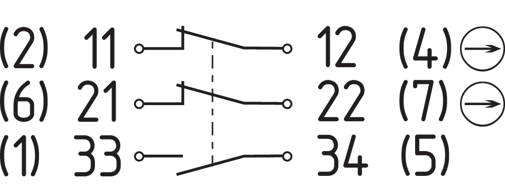
| Switching element |
1 NO contact, 2 NC contacts |
| Note (Switching element) |
Change-over contact with double break, type Zb or 3 NC contacts, with galvanically separated contact bridges |
| Switching principle |
slow action, positive break NC contact |
| Maximale Schalthäufigkeit |
1,200 /h |
| Material of the contacts, electrical |
Silver |
Electrical data - Safety contacts
| Voltage, Utilisation category AC-15 |
230 VAC |
| Current, Utilisation category AC-15 |
3 A |
| Voltage, Utilisation category DC-13 |
24 VDC |
| Current, Utilisation category DC-13 |
3 A |
Electrical data - Auxiliary contacts
| Voltage, Utilisation category AC-15 |
230 VAC |
| Current, Utilisation category AC-15 |
3 A |
| Voltage, Utilisation category DC-13 |
24 VDC |
| Current, Utilisation category DC-13 |
3 A |
Other data
| Note (applications) |
sliding safety guard removable guard hinged safety guard |
Scope of delivery
| Scope of delivery |
Actuator must be ordered separately. Slot cover for dust-proof covering of the opening not in use |
Language filter
Datasheet
Operating instructions and Declaration of conformity
CCC certification
SISTEMA-VDMA library
Download the latest version of Adobe Reader
Product picture (catalogue individual photo)
Dimensional drawing basic component

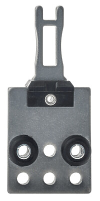
157000540 AZ21X/31X-B1
- Straight actuator
- Particularly suitable for sliding doors
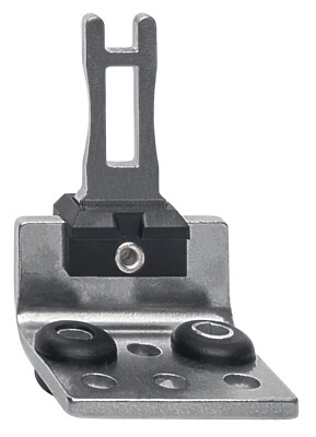
157000541 AZ21X/31X-B5
- Angled actuator
- Particularly suitable for sliding doors

157000543 AZ21X/31X-B6
- Flexible actuator
- Particularly suitable for hinged guards
| EU Declaration of Conformity |  |
| Original | K.A. Schmersal GmbH & Co. KG Möddinghofe 30 42279 Wuppertal Germany Internet: www.schmersal.com |
| Declaration: | We hereby certify that the hereafter described components both in their basic design and construction conform to the applicable European Directives. |
| Name of the component: | AZ215 AZ216 AZ315 AZ316 |
| Type: | See ordering code |
| Description of the component: | Positive break position switch with separate actuator for safety functions |
| Relevant Directives: | Machinery Directive | 2006/42/EC |
| RoHS-Directive | 2011/65/EU |
| Applied standards: | EN 60947-5-1:2017 + AC:2020 |
| Person authorised for the compilation of the technical documentation: | Oliver Wacker Möddinghofe 30 42279 Wuppertal |
| Place and date of issue: | Wuppertal, August 4, 2023 |
 |
| Authorised signature Philip Schmersal Managing Director |
K.A. Schmersal GmbH & Co. KG, Möddinghofe 30, 42279 Wuppertal
The details and data referred to have been carefully checked. Images may diverge from original. Further technical data can be found in the manual. Technical amendments and errors possible.
Generated on: 02/10/2025, 18:55
Recently viewed

SHGV/B01/112+BOW

IFL-N-4-12-01P
TR 235-02ZH
ZS 332-11Y-M20
