BDF200-ST1-AS-NH-SWS20S1-LTWH-LTBU
BDF200-ST1-AS-NH-SWS20S1-LTWH-LTBU
Downloads
| Product type description: BDF 200-(1)-AS-(2)-(3)-(4)-(5)-(6) |
| (1) | |
| ST1 | Connector plug M12 - plastic - bottom |
| ST2 | Connector plug M12, above |
| (2) | |
| NH | Emergency stop pushbutton without protective collar |
| NHK | Emergency stop with protective collar |
| (3) | |
| WS 2/3 | Selector switch, 2/3 switch position |
| WT 2/3 | Selector switch, 2/3 switch positions |
| SW 20 | Key switch/button, 2 switch positions |
| LT.. | Illuminated control push button (selection colour) |
| LM.. | Indicator light (selection colour) |
| DT.. | Push button (Selection Color) |
| (4) | |
| LT.. | Illuminated control push button (selection colour) |
| LM.. | Indicator light (selection colour) |
| DT.. | Push button (Selection Color) |
| (5) | |
| LT.. | Illuminated control push button (selection colour) |
| LM.. | Indicator light (selection colour) |
| DT.. | Push button (Selection Color) |
| (6) | |
| without | without indicator lamp G24 |
| G24 | with indicator lamp G24 |
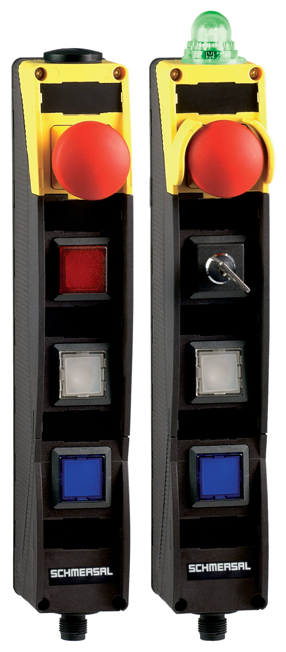
- Integrated AS-Interface
- with connector plug M12 bottom
- Pos 1: E-STOP
- Pos 2: Key selector switch, 2 positions, key removable position 0
- Pos 3: WHITE illuminated pushbutton
- Pos 4: BLUE illuminated pushbutton
- slender shock-proof thermoplastic enclosure
- to be installed at an ergonomic favourable position
- to be fitted to commercial-off-the-shelf aluminium profiles
Ordering data
| Product type description |
BDF200-ST1-AS-NH-SWS20S1-LTWH-LTBU |
| Article number (order number) |
103040306 |
| EAN (European Article Number) |
4030661553450 |
| eCl@ss number, version 12.0 |
27-37-12-16 |
| eCl@ss number, version 11.0 |
27-37-12-16 |
| eCl@ss number, version 9.0 |
27-37-12-16 |
| ETIM number, version 7.0 |
EC000225 |
| ETIM number, version 6.0 |
EC000225 |
| Note (Ordering data) |
Notice: see ordering code |
Approvals - Standards
| Certificates |
cULus ASi-SaW |
General data
| Standards |
EN IEC 62026-2 EN ISO 13849-1 EN ISO 13850 EN IEC 60947-5-1 EN IEC 61508 |
| Climatic stress |
DIN EN 60068 |
| Housing material |
Plastic, glass-fibre reinforced thermoplastic, self-extinguishing |
| Reaction time, maximum |
100 ms |
| Positions used, position 1 |
Emergency stop pushbutton |
| Positions used, position 2 |
Key selector switch 3 positions |
| Positions used, position 3 |
Illuminated pushbutton, white |
| Positions used, position 4 |
Illuminated pushbutton, blue |
| Gross weight |
280 g |
General data - Features
| Indicator lamp |
No |
| Safety classification |
| Vorschriften |
EN IEC 61508 |
| Performance Level, up to |
e |
| Category |
4 |
| PFH value |
1.40 x 10⁻⁸ /h |
| Note (PFH-value) |
up to max. 5,000 switching cycles/year |
| Safety Integrity Level (SIL), suitable for applications in |
3 |
| Mission time |
20 Year(s) |
Mechanical data
| Mechanical life, Emergency-Stop button |
100,000 Operations |
| Mechanical life, Command devices |
1,000,000 Operations |
| Mounting |
interior mounting holes |
| Type of the fixing screws |
2x M5 |
Mechanical data - Connection technique
| Termination |
Connector plug M12, 4-pole, (A-coding) |
Mechanical data - Dimensions
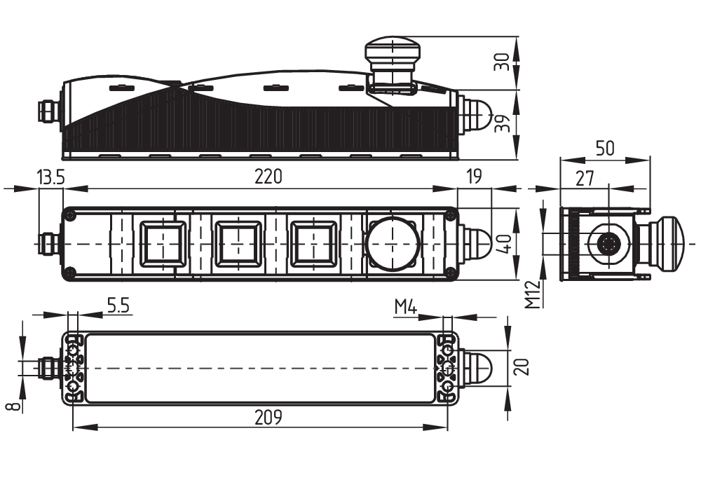
| Width |
40 mm |
| Height |
69 mm |
| Depth |
233.5 mm |
Ambient conditions
| Degree of protection |
IP65 |
| Ambient temperature |
-25 ... +65 °C |
| Storage and transport temperature |
-25 ... +85 °C |
| Resistance to vibrations |
10 … 150 Hz, amplitude 0.35 mm / 5 g |
| Restistance to shock |
15 g / 11 ms |
| Protection class |
II |
| Permissible installation altitude above sea level, maximum |
2,000 m |
Ambient conditions - Insulation values
| Rated insulation voltage Ui |
32 VDC |
| Rated impulse withstand voltage Uimp |
0.8 kV |
| Overvoltage category |
III |
| Degree of pollution |
3 |
Electrical data - AS Interface
| Rated operating voltage |
18 ... 31.6 VDC (Protection against polarity reversal) |
| AS-i Current consumption, maximum |
150 mA |
Electrical data - AS-Interface specification
| Note (AS-i Parameter bits) |
Set the parameter outputs to "1111" (0xF) FID: periphery error |
| AS-i Version (Safety-Slave) |
V 3.0 |
| AS-i Profile (Safety-Slave) |
S-7.B.F.F |
| AS-i Input, Channel 1 (Safety-Slave) |
Data bits DI 0 / DI 1 = dynamic code transmission |
| AS-i Input, Channel 2 (Safety-Slave) |
Data bits DI 2 / DI 3 = dynamic code transmission |
| AS-i Output, DO 0 (Safety-Slave) |
Indicator lamp G24 red |
| AS-i Output, DO 1 (Safety-Slave) |
Indicator lamp G24 green |
| AS-i Output, DO 2 (Safety-Slave) |
No Function |
| AS-i Output, DO 3 (Safety-Slave) |
No Function |
| AS-i AS-i Parameter bits (Safety-Slave), P0 ... P3 |
No function |
| AS-i Version (A/B Slave) |
V 3.0 |
| AS-i Profile (A/B Slave) |
S-7.A.7.F |
| AS-i Input, DI 0 (A/B Slave) |
Command device Position 4 |
| AS-i Input, DI 1 (A/B Slave) |
Command device Position 3 |
| AS-i Input, DI 2 (A/B Slave) |
Command device Position 2 |
| AS-i Input, DI 3 (A/B Slave) |
Command device Position 2 |
| AS-i Output, DO 0 (A/B Slave) |
Illuminated signal position 4 |
| AS-i Output, DO 2 (A/B Slave) |
Illuminated signal position 2 |
| AS-i Output, DO 1 (A/B Slave) |
Illuminated signal position 3 |
| AS-i Output, DO 3 (A/B Slave) |
No Function |
| AS-i AS-i Parameter bits (A/B Slave), P0 ... P3 |
No function |
| AS-i Input module address |
0 |
| Note (AS-i Input module address) |
Preset to address 0, can be changed through AS-interface bus master or hand-held programming device |
| Note |
Both AS-i slaves can be enabled and disabled through the integrated DIP switch. The addressing must take place via the M12 connector. |
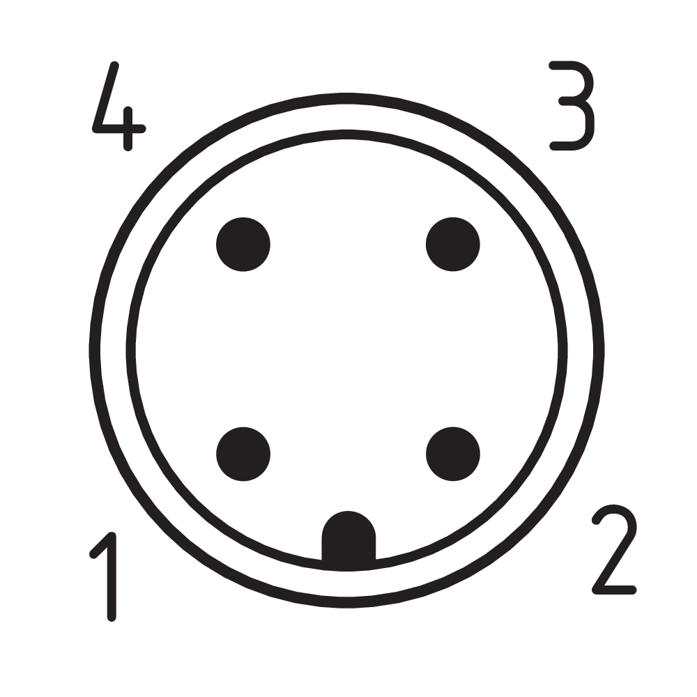
Pin assignment
| PIN 1 |
AS-Interface + |
| PIN 2 |
n.c. |
| PIN 3 |
AS-Interface - |
| PIN 4 |
n.c. |
Language filter
Datasheet
Operating instructions and Declaration of conformity
UL Certificate
AS interface safety at work certificate
Download the latest version of Adobe Reader
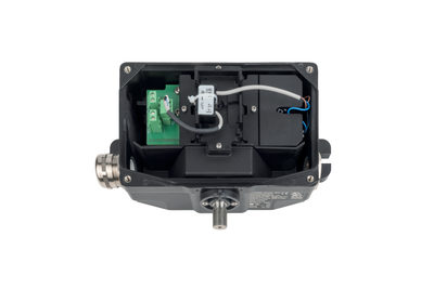
Product picture (catalogue individual photo)
Dimensional drawing basic component
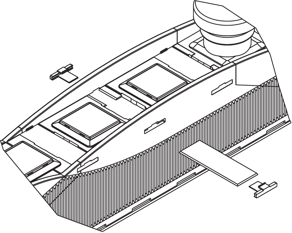
Operating principle
Clipart

Contact arrangement
| EU Declaration of Conformity |  |
| Original | K.A. Schmersal GmbH & Co. KG Möddinghofe 30 42279 Wuppertal Germany Internet: www.schmersal.com |
| Declaration: | We hereby certify that the hereafter described components both in their basic design and construction conform to the applicable European Directives. |
| Name of the component: | BDF200AS |
| Type: | See ordering code |
| Description of the component: | Control panel with or without safety function and integrated AS interface |
| Relevant Directives: | Machinery Directive 1) | 2006/42/EC |
| Low Voltage Directive | 2014/35/EU | |
| EMC-Directive | 2014/30/EU | |
| RoHS-Directive | 2011/65/EU | |
| 1) For device versions with safety function | ||
| Applied standards: | EN 60947-5-1:2017 + AC:2020 1) EN 60947-5-5:1997 + A1:2005 + A11:2013 + A2:2017 1) EN ISO 13849-1:2023 1) EN 61508-1:2010 |
| Person authorised for the compilation of the technical documentation: | Oliver Wacker Möddinghofe 30 42279 Wuppertal |
| Place and date of issue: | Wuppertal, December 10, 2024 |
 |
| Authorised signature Philip Schmersal Managing Director |
K.A. Schmersal GmbH & Co. KG, Möddinghofe 30, 42279 Wuppertal
The details and data referred to have been carefully checked. Images may diverge from original. Further technical data can be found in the manual. Technical amendments and errors possible.
Generated on: 15/07/2025, 22:57
Recently viewed