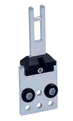
US 431Y-M20
US 431Y-M20
Downloads
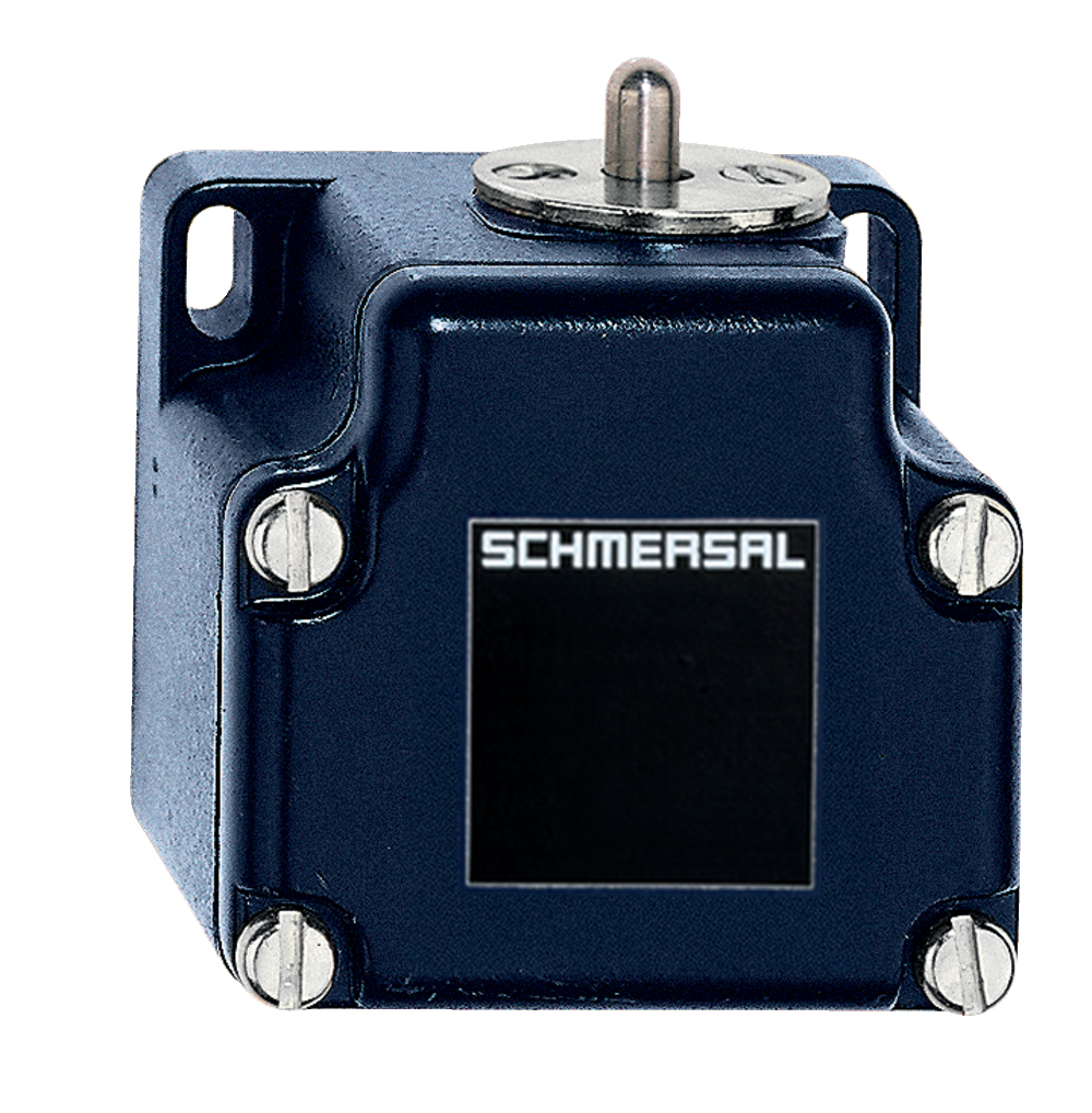
- Metal enclosure
- 1 Contact
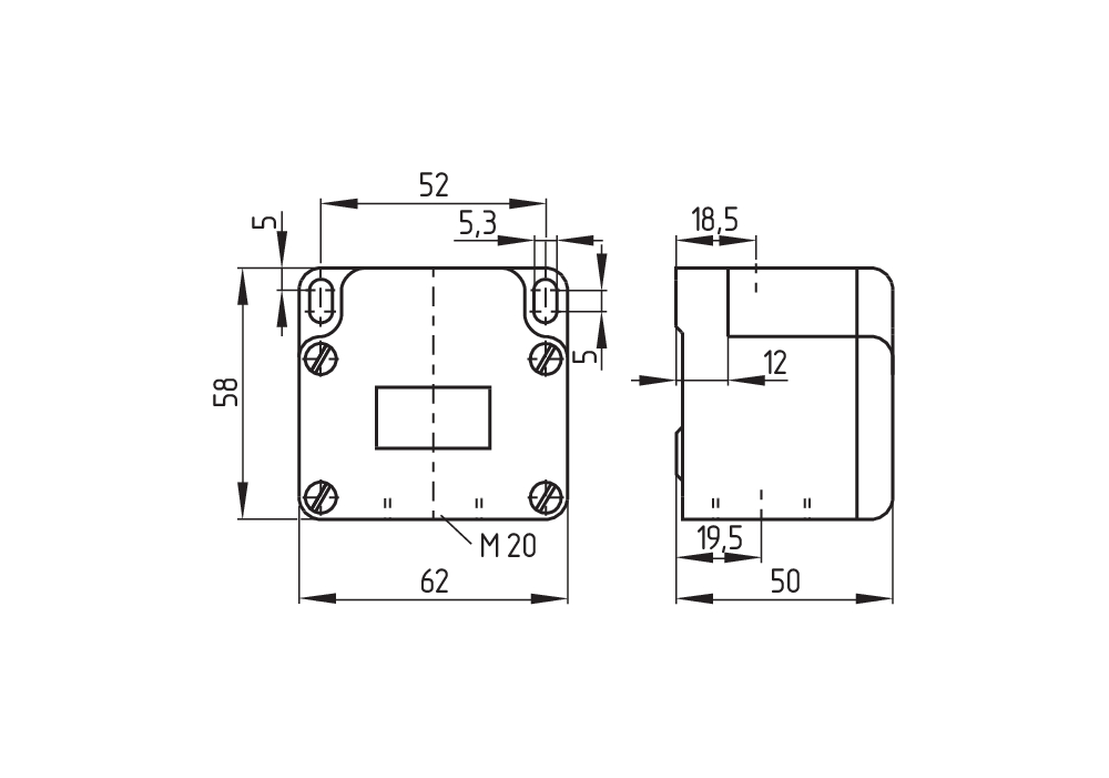
- 62 mm x 58 mm x 50 mm ( basic component)
- Switching points and contact function adjustable
- 1 Cable entry M 20 x 1.5
Ordering data
| Product type description |
US 431Y-M20 |
| Article number (order number) |
101175221 |
| EAN (European Article Number) |
4030661304519 |
| eCl@ss number, version 12.0 |
27-27-06-01 |
| eCl@ss number, version 11.0 |
27-27-06-01 |
| eCl@ss number, version 9.0 |
27-27-06-01 |
| ETIM number, version 7.0 |
EC000030 |
| ETIM number, version 6.0 |
EC000030 |
Approvals - Standards
| Certificates |
cULus |
General data
| Standards |
EN IEC 60947-5-1 |
| Working principle |
mechanical |
| Slide form |
Sphere |
| Housing material |
Light alloy die-casting |
| Housing coating material |
painted |
| Gross weight |
245 g |
General data - Features
| Number of normally closed (NC) |
1 |
Mechanical data
| Actuating element |
Plunger |
| Mechanical lifetime, minimum |
10,000,000 Operations |
| Actuating angle |
20 ° |
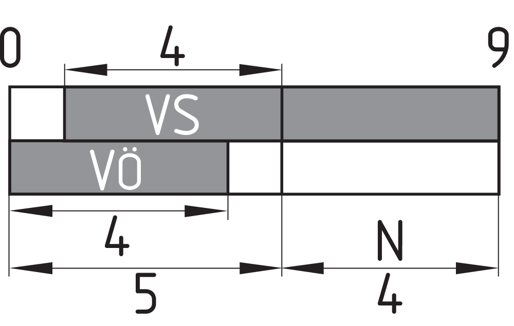
| Contact opening |
2 x 1.5 mm |
| Actuating speed, minimum |
1 mm/min |
| Actuating speed, maximum |
1 m/s |
| Note (Actuating speed) |
Actuating speed with vertical actuating angle to switch axis |
Mechanical data - Connection technique
| Termination |
Screw terminals M20 x 1.5 |
| Cable section, minimum |
1.5 mm² |
| Cable section, maximum |
2.5 mm² |
| Note |
All indications including the conductor ferrules. |
| Wire cross-section |
13 AWG |
Mechanical data - Dimensions
| Length of sensor |
50 mm |
| Width of sensor |
62 mm |
| Height of sensor |
69 mm |
| Diameter of the Plunger |
6 mm |
Ambient conditions
| Degree of protection |
IP65 |
| Ambient temperature |
-20 ... +60 °C |
Ambient conditions - Insulation values
| Rated insulation voltage Ui |
500 V |
Electrical data
| Thermal test current |
16 A |
| Switching element |
Opener (NC) |
| Switching principle |
Slow action |
| Material of the contacts, electrical |
Silver |
Note
| Note (General) |
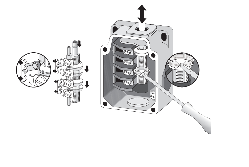
Type of contact and switching points can be factory set to order. Actuation from the side of the plunger should be avoided, since this reduces the mechanical life of the position switch. |
Language filter
Datasheet
Operating instructions (supplementary sheet/quick guide)
EC Declaration of conformity
UL Certificate
Download the latest version of Adobe Reader
Product picture (catalogue individual photo)
Dimensional drawing basic component
Dimensional drawing actuator

Switch travel diagram
Diagram

Operating principle

K.A. Schmersal GmbH & Co. KG, Möddinghofe 30, 42279 Wuppertal
The details and data referred to have been carefully checked. Images may diverge from original. Further technical data can be found in the manual. Technical amendments and errors possible.
Generated on: 02/10/2025, 13:53
Recently viewed
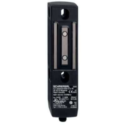
MZM 100 B ST2-1P2PW2REM-A-DU
SVE2/113/113-3Ö-24VDC
HWSE4-BL-SW
SHGV/RD1/207/33+BO

SMS 4-680-880

V-SK8P-M12-S-G-3,5M-BK-2-X-A-4-69

SHGV/B01/211+BOW