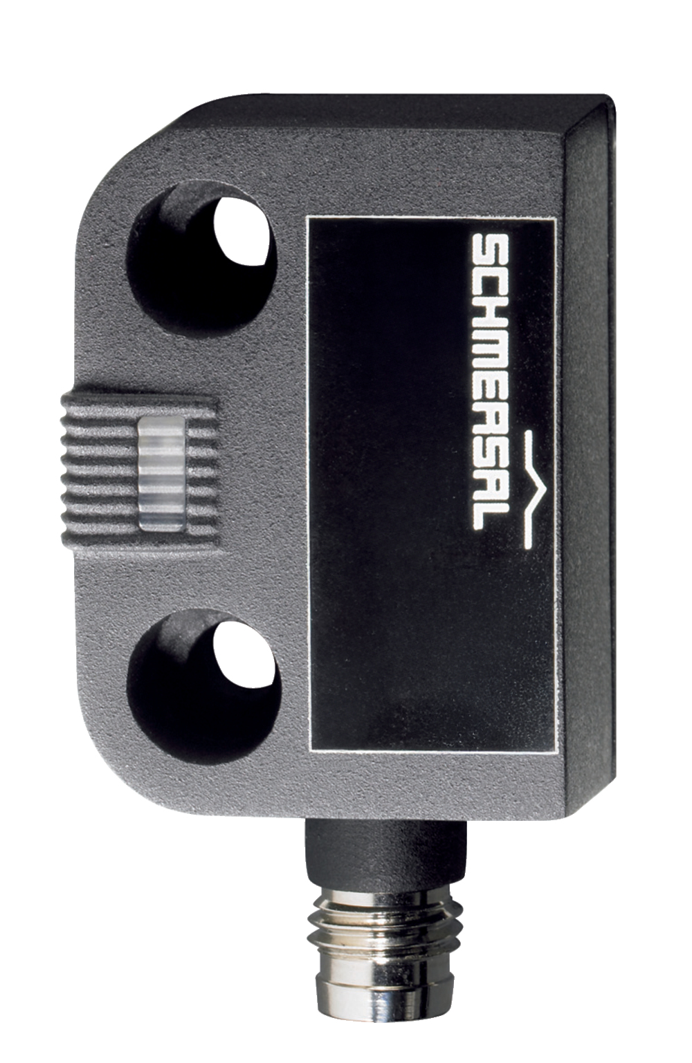
BNS 260-02ZG-ST-R
| 製品タイプの説明: BNS 260-(1)(2)Z(3)-(4)-(5) |
| (1) | |
| 11 | 1 NO 接点 / 1 NC 接点 |
| 02 | 2 NC接点 |
| (2) | |
| なし | 診断出力付き |
| /01 | 1 NC接点 |
| (3) | |
| なし | 開閉状態表示LEDなし |
| G | 開閉状態表示LED付き |
| (4) | |
| なし | 既配線ケーブル |
| ST | コネクタ式 |
| (5) | |
| L | 左開き用ドアヒンジ |
| R | 右開き用ドアヒンジ |
- コネクターM8 x 1, 4芯
- 熱可塑性樹脂性ケース
- 小型
- カバー内取り付け可能
- 26 mm x 36 mm x 13 mm
- 長寿命
- 機械的磨耗なし
- 横方向の位置ズレ防止
- 汚れに強い
注文データ
| 製品タイプの説明 |
BNS 260-02ZG-ST-R |
| 部品番号(注文番号) |
101184365 |
| EAN(欧州部品番号) |
4030661321622 |
| eCl@ss番号、バージョン12.0 |
27-27-44-01 |
| eCl@ss番号、バージョン11.0 |
27-27-24-02 |
| eCl@ss番号、バージョン9.0 |
27-27-24-02 |
| ETIM番号、バージョン7.0 |
EC002544 |
| ETIM番号、バージョン6.0 |
EC002544 |
認証
|
cULus |
一般データ
| 規格 |
BG-GS-ET-14 EN IEC 60947-5-3 |
| EN ISO 14119に準拠したコーディングレベル |
Low |
| アクティブ原理 |
磁気装置 |
| 取り付け条件(機械式) |
適切な横幅の |
| ハウジング 材質 |
グラスファイバー強化熱可塑性樹脂 |
| 総重量 |
33 g |
一般データ - 仕様
| コード化 |
Yes |
| 一体型システム診断、状態 |
Yes |
| NC接点の数 |
2 |
| 安全接点数 |
2 |
安全性評価
| 規定 |
EN ISO 13849-1 |
| ミッションタイム |
20 年 |
安全性評価 - 安全出力
| B10D NC接点 |
25,000,000 操作 |
| B10D 值 NC接点/NO接点 |
25,000,000 操作 |
機械的データ
| 動作エレメント |
ソレノイド |
| ドアヒンジ |
Right |
| 動作方向 |
Head-on to the active surface |
Mechanical data - Switching distances
| 注記 (動作距離 Sn) |
Axial misalignment, a horizontal and vertical misalignment of the safety sensor and the actuator are tolerated. The possible misalignment depends on the distance of the active surfaces of the sensor and the actuator. The sensor remains active within the tolerance range. |
| 安定動作距離 "ON" Sao |
5 mm |
| 安定動作距離 "OFF" Sar |
15 mm |
| 注記 (動作距離) |
All switching distances in accordance EN IEC 60947-5-3 |
機械的データ - 電気機械式
| 接続 |
M8コネクター |
| 電気接続部の締付けトルク |
0.3 Nm |
機械的データ - 寸法
| センサー長 |
13 mm |
| センサーの幅 |
26 mm |
| センサーの高さ |
36 mm |
環境条件
| 保護等級 |
IP67 |
| 使用周囲温度 |
-25 ... +70 °C |
| 保管および輸送温度 |
-25 ... +70 °C |
| 耐振動 |
10 ~ 55 Hz, 振幅 1 mm |
| 耐衝撃 |
30 g / 11 ms |
環境条件 - 絶縁値
| 定格絶縁電圧 Ui |
75 VDC |
| 定格インパルス耐電圧 Uimp |
0.8 kV |
電気的データ
| 要求定格短絡電流 |
100 A |
| 開閉電圧、最大 |
24 VDC |
| スイッチング電流, 最大 |
0.01 A |
| 開閉容量、最大 |
0.24 W |
| スイッチエレメント |
2 NC接点 |
| 開閉頻度、最大 |
5 Hz |
状態表示
| 注記 (統合システム診断、状態) |
The LED is illuminated when the guard is closed. |
納入品目
| 納入時同梱 |
Actuator must be ordered separately. |
アクセサリー
| 推奨(アクチュエーター) |
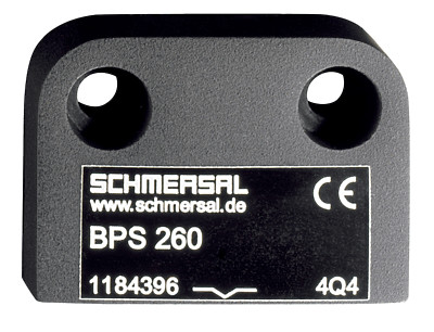
BPS 260 |
| 推奨セーフティスイッチ |
SRB-E-301ST SRB-E-201LC |
Note
| 注記 (一般) |
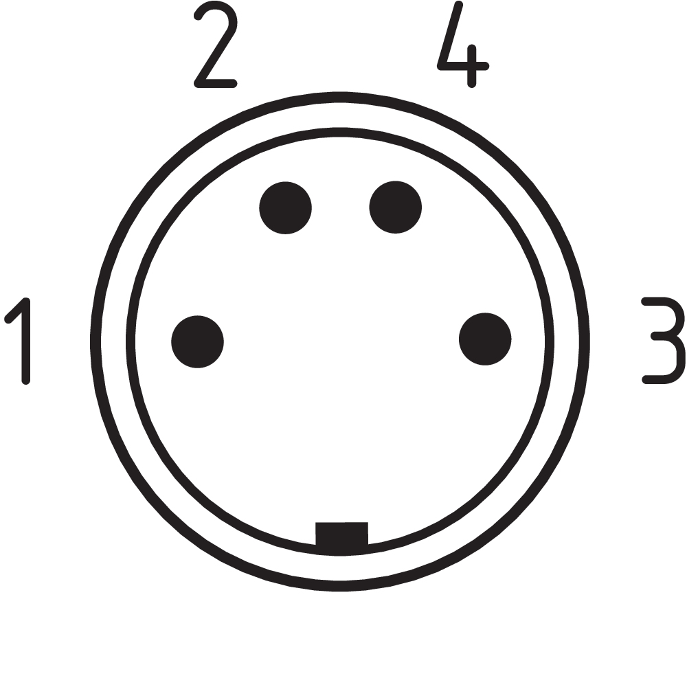
The number in brackets indicate the PIN number of the connector. |
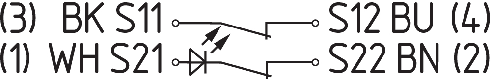
回路例
| 注記 (配線図) |
The contacts S11-S12 and S21-S22 must be integrated in the safety circuit. |
言語フィルター
データシート
Operating Instructions and Declaration of Conformity (Short)
UL Certificate
SISTEMA-VDMA library
Adobe Readerの最新版をダウンロードしてください
Product picture (catalogue individual photo)
Dimensional drawing basic component
Diagram
Characteristic curve
Characteristic curve
Clipart
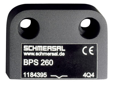
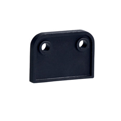
101184643 スペーサー BNS 260
- セーフティ磁気センサとアクチュエータの強磁性素材への取り付け用

103007672 SRB-E-301ST
- STOP 0 機能
- 1 oder 2チャンネルコントロール
- リセットボタン / 自動リセット
- 1 補助接点
- 3 安全出力

103009970 SRB-E-201LC
- STOP 0 機能
- 1 oder 2チャンネルコントロール
- リセットボタン / 自動リセット
- 2 安全出力 2 A
- 1 補助出力

103009973 SRB-E-204ST
- STOP 0 機能
- 4 センサーの監視
- リセットボタン / 自動リセット
- 2 安全出力
- 4 補助出力
101194060 BNS-Y-02
- セーフティ・センサBNSを共通のセーフティ・リレー・ユニット上で行うためにBNSの切断が可能
- 該当 BNS 33, BNS 36, BNS 260 (付 2 NC)
Table of Contents
1 この文書について
1.1 機能
本書は、本製品の安全な操作と解体のために、取付け、セットアップ、試運転に必要なすべての情報を提供します。装置に同封されている取扱説明書は、読み易い状態で、完全版を機器の付近に保管してください。
1.2 取扱説明書の対象グループ: 認定された有資格者
この取扱説明書に記述された全ての操作は、使用者によって認められた専門技術者が行ってください。
この取扱説明書を熟読し、コンポーネントの据付及び運転の前に、労働安全及び事故予防のための適用可能な全規定に付いてご確認ください。
組み立て作業員は、コンポーネントの選定、取り付け、内蔵に対して、他の技術仕様を遵守するのと同じように、慎重に整合規格を選択しなければなりません
仕様などの記載内容について予告なく変更する事があります。あらかじめご了承ください
1.3 使用記号の説明
- 情報、助言、注釈:この表示は役立つ追加情報を示します。
- 注意: 取り扱いを誤った場合に、故障、機能不良が想定される内容を示しています。
警告:取り扱いを誤った場合に、傷害を負う可能性が想定される内容、及び物的損害の発生が想定される内容を示しています。
1.4 適切な使用
シュメアザールが提供する製品は、個人消費者向けではありません。
本製品は、設備や機械の一部として安全関連機能を果たすために開発されたものです。設備や機械全体が適格に動作する事を保証する事は、製造者の責任です。
セーフティスイッチは下記に挙げられたバージョン、又は製造者によって許可されたアプリケーションに対してのみ使用しなければなりません。アプリケーションの範囲に関する詳細は、「製品内容」の項を参照ください。
1.5 安全上のご注意
ユーザーはこの取扱説明書に記載されている、安全上の説明、各国の設置基準、並びに全ての周知の安全規則や事故防止規則を遵守しなければなりません。
- 詳細な技術情報に付いてはシュメアザールカタログ、又はインターネット(products.schmersal.com)上のオンラインカタログをご参照下さい。
1.6 誤使用に関する警告
- 本製品の不十分、不適切な使用及び無効化の際は、人への危険、機械、設備への損害を負う可能性があります。取付、据付、操作及び保全に関する説明書と同様に安全に関する注意が遵守されていれば、残留リスクはありません。
1.7 免責事項
誤った取り付けやこの取扱説明書を正しく理解していないために起こった損害、故障はシュメアザールの免責事項となります。また、製造者に許可されていない代替・付属品による損害は、製造者の免責事項となります。
安全上の理由から、デバイスに対する独自の変更や不適切な修理、部品の交換や改造は厳として認められず、それが理由で発生した故障や事故に対し、シュメアザールは責任を一切負いません。
2 製品内容
2.1 型番
| 製品タイプの説明: BNS 260-(1)(2)Z(3)-(4)-(5) |
| (1) | |
| 11 | 1 NO 接点 / 1 NC 接点 |
| 02 | 2 NC接点 |
| (2) | |
| なし | 診断出力付き |
| /01 | 1 NC接点 |
| (3) | |
| なし | 開閉状態表示LEDなし |
| G | 開閉状態表示LED付き |
| (4) | |
| なし | 既配線ケーブル |
| ST | コネクタ式 |
| (5) | |
| L | 左開き用ドアヒンジ |
| R | 右開き用ドアヒンジ |
2.2 特殊仕様
型式記号で挙げられていない特別仕様は一般使用に準じます。
2.3 目的
セーフティセンサーBNS 260は、EN ISO 14119 及びEN 60947-5-3に準拠して、安全回路内の可動式ガードの位置監視用に設計されています。セーフティセンサーの作動には、アクチュエーターBPS 260-1或いはBPS 260-2のみ使用する事が可能です。
セーフティスイッチは、ガードが開いた時に、危険な状態が直ちに終了するアプリケーションで使用します。
- セーフティスイッチは、EN ISO 14119に基づきタイプ4のインターロック機器に分類されます。
セーフティセンサー(BNS 260)、アクチュエーター(BPS 260-1,260-2)及びセーフティリレーユニット(SRB)の組み合わせでのみ、規格EN 60947-5-3の要求事項に適合します。
- 使用者は関連規格や安全レベルの要求に基づき、安全な接続を検証し、設計しなければなりません。
- セーフティコンポーネントが組み込まれた制御システムの全体的な構想は、関連規格に対して妥当性を確認しなければなりません。
2.4 技術データ
認証
|
cULus |
一般データ
| 規格 |
BG-GS-ET-14 EN IEC 60947-5-3 |
| EN ISO 14119に準拠したコーディングレベル |
Low |
| アクティブ原理 |
磁気装置 |
| 取り付け条件(機械式) |
適切な横幅の |
| ハウジング 材質 |
グラスファイバー強化熱可塑性樹脂 |
| 総重量 |
33 g |
一般データ - 仕様
| コード化 |
Yes |
| 一体型システム診断、状態 |
Yes |
| NC接点の数 |
2 |
| 安全接点数 |
2 |
安全性評価
| 規定 |
EN ISO 13849-1 |
| ミッションタイム |
20 年 |
安全性評価 - 安全出力
| B10D NC接点 |
25,000,000 操作 |
| B10D 值 NC接点/NO接点 |
25,000,000 操作 |
機械的データ
| 動作エレメント |
ソレノイド |
| ドアヒンジ |
Right |
| 動作方向 |
Head-on to the active surface |
Mechanical data - Switching distances
| 注記 (動作距離 Sn) |
Axial misalignment, a horizontal and vertical misalignment of the safety sensor and the actuator are tolerated. The possible misalignment depends on the distance of the active surfaces of the sensor and the actuator. The sensor remains active within the tolerance range. |
| 安定動作距離 "ON" Sao |
5 mm |
| 安定動作距離 "OFF" Sar |
15 mm |
| 注記 (動作距離) |
All switching distances in accordance EN IEC 60947-5-3 |
機械的データ - 電気機械式
| 接続 |
M8コネクター |
| 電気接続部の締付けトルク |
0.3 Nm |
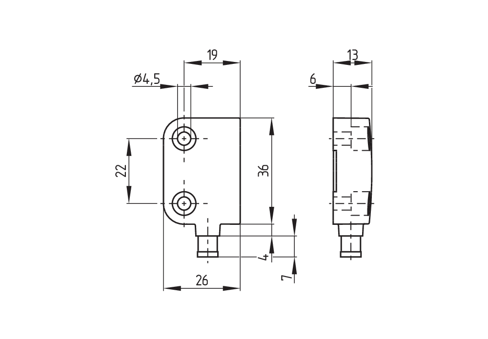
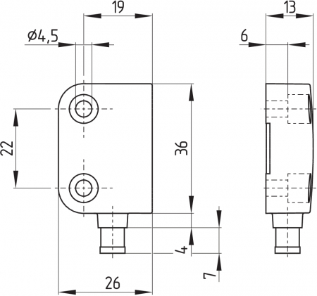
機械的データ - 寸法
| センサー長 |
13 mm |
| センサーの幅 |
26 mm |
| センサーの高さ |
36 mm |
環境条件
| 保護等級 |
IP67 |
| 使用周囲温度 |
-25 ... +70 °C |
| 保管および輸送温度 |
-25 ... +70 °C |
| 耐振動 |
10 ~ 55 Hz, 振幅 1 mm |
| 耐衝撃 |
30 g / 11 ms |
環境条件 - 絶縁値
| 定格絶縁電圧 Ui |
75 VDC |
| 定格インパルス耐電圧 Uimp |
0.8 kV |
電気的データ
| 要求定格短絡電流 |
100 A |
| 開閉電圧、最大 |
24 VDC |
| スイッチング電流, 最大 |
0.01 A |
| 開閉容量、最大 |
0.24 W |
| スイッチエレメント |
2 NC接点 |
| 開閉頻度、最大 |
5 Hz |
状態表示
| 注記 (統合システム診断、状態) |
The LED is illuminated when the guard is closed. |
回路例
| 注記 (配線図) |
The contacts S11-S12 and S21-S22 must be integrated in the safety circuit. |
安全分類に関する注意事項
適切なロジックで2チャンネル使用する場合、Cat. 4 / PL eまで使用可能。
(決定された値は、アプリケーション固有のパラメータであるh1op2d3op4and t5cycle6負荷によって変化する可能性があります。78複数のセーフティコンポーネントを直列に接続する場合、一定の状況下で制限されたエラー検知機能により、EN ISO 13849-1 に基づくパフォーマンスレベルが低下します。
UL 規格
- NFPA 79アプリケーションで使用する場合には、 フィールド配線の手段を提供するアダプターは、メーカーから入手出来ます。メーカーの情報をご参照ください。
3 取り付け
3.1 通常の取り付け方法
- 取り付けの際はEN ISO 14119の要求を順守して下さい。
- 取り付けは非通電の状態で行って下さい
- センサーとアクチュエーターをストッパーとしては使わないでください
- センサーとアクチュエーターの検出面が向かい合っていれば、取り付け位置は自由です
- センサーとアクチュエーターに、極端な振動と衝撃を与えないでください
このようなシステム特有の障害、干渉や動作距離の減少を避けるために、次のガイドラインを遵守してください。
- セーフティセンサーが平面に取り付けられている事を確認してください
- セーフティセンサーとアクチュエーターを強力な磁場のあるところには取り付けないでください
- センサーとアクチュエーターを強磁性体の材質に取り付けないでください。厚さが少なくとも5 mmの非磁性体スペーサーか、既製品のスペーサーを使わなければなりません。又、非磁性体の取り付けネジの使用をお勧めします。
- 金属片を近付けないでください
- 2つのセンサーの間は、少なくとも50 mmあけてください。
- アクチュエータはガードに確実に取り付け、適切な方法(無効化防止ネジ、接着、ネジヘッドをつぶすなど)により取り外しが出来ないようにしなければなりません。
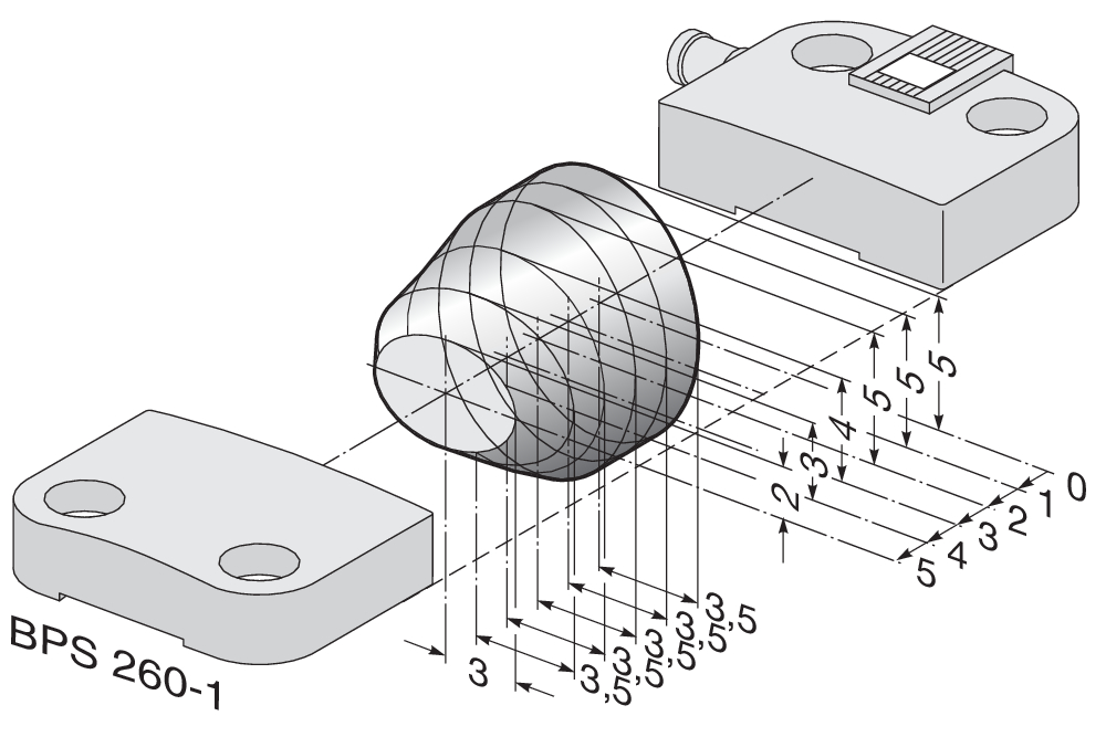
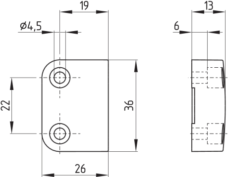
3.2 外形図
全ての寸法表記はmm
コネクター付きセンサー、右ヒンジドア用
ケーブル付セーフティセンサー、左ヒンジドア用

アクチュエータ
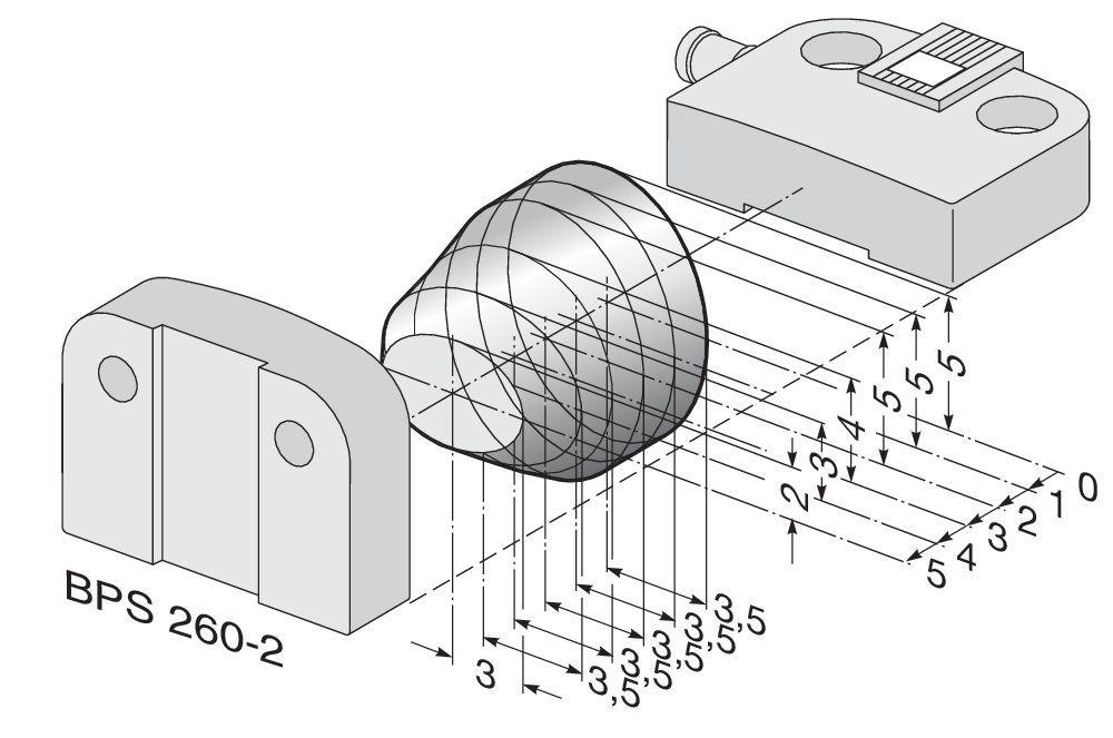
3.3 横方向の位置ズレ
セーフティセンサーとアクチュエーターの水平、垂直位置がズレていても動作します。動作可能なズレの範囲は、センサーとアクチュエーターの検出面の距離によります。センサーは許容範囲内で動作します。
指定された動作距離は、相対するセーフティセンサーとアクチュエーターを参照してください。


| 安定動作距離: | sao | = | 5 mm 8 mm (型式末尾 -2750) |
| 安定復帰距離: | sar | = | 15 mm 18 mm (型式末尾 -2750) |
3.4 調整
- 推奨される調整
セーフティセンサーとアクチュエーターの距離を 0.5 x saoで調整してください。
セーフティセンサーとアクチュエーターのセンターマークを互いに合わせてください。LEDは大まかな調整用として使えます。両方の安全出力が正しく機能しているかどうか、接続されたセーフティリレーユニットなどで確認する必要があります。
4 電気配線
4.1 電気配線上のご注意
- 電気配線は専門技術者が非通電の状態で行って下さい。
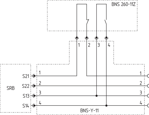
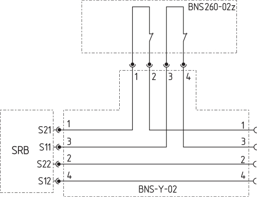
複数のセーフティセンサーを1個のセーフティリレーユニットSRBに接続する事が出来ます。複数のセーフティセンサーを接続するには(認められているのかチェックが必要!)、NO接点を並列に、NC接点を直列に接続します。入力拡張ユニットProtect-IE-11又は-02或いはPROTECT-PE-11 (-AN)又は-02を使うと、最大4個のNC/NC接点タイプか、NC/NO接点タイプのセーフティセンサーが接続出来ます。
LED付きのセーフティセンサーは、PROTECT-IE又はPROTECT-PEを使う時以外は、直列に接続してはなりません。そうしないとLEDの輝度は大幅に減少し、下位のセーフティリレーユニットの最低入力電圧を下回る事があります。
- 適切なセーフティリレーユニットの選択に関する情報は、Schmersalのカタログか、インターネット (products.schmersal.com) 上にあるオンラインカタログをご覧ください。
4.2 接点オプション
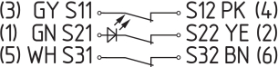
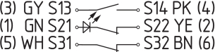
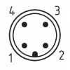
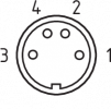
セーフティセンサーの配線は、配線色かピン配置に従って行わなければなりません。
接点の状態表示はガードが閉じて、センサーが動作している時のものです。LED付きセーフティセンサーの場合、LEDはガードが閉じている時に点灯します。接点の設定はLED付き、なしで同じです。
| 安全接点: | S21-S22 及び S11-S12 または S13-S14 |
| 補助接点: | S31-S32 |
括弧内の数字はコネクター付きのバージョンか、コネクター付きケーブルのピン配置を表しています。配線色はケーブル引き出しタイプの色。
| BNS 260-02Z(G) | BNS 260-11Z(G) |
|---|---|
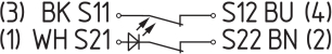 | 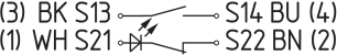 |
| BNS 260-02/01Z(G) | BNS 260-11/01Z(G) |
|---|---|
 |  |
4.3 アクセサリー
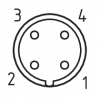
| コネクタープラグ又はケーブルコネクター | ||
|---|---|---|
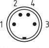 | 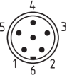 |  |
| M8, 4極, ネジ端子 又はラッチ接続 | 8 mm, 6極, ワンタッチ取り付け | M12, 4極, ネジ接続 振動保護装置付き |
アクセサリー: カップリング付き接続ケーブル
| M8, 4芯, ネジ端子付き | 2 m | 5 m | 10 m | |||
|---|---|---|---|---|---|---|
 | 1 | 茶 | ストレート | 103011340 | 103007356 | - |
| 2 | 白 | |||||
| 3 | 青 | アングル | 101210557 | 101210559 | - | |
| 4 | 黒 | |||||
| 8 mm, 6芯, ワンタッチ取り付け | 2 m | 5 m | 10 m | |||
|---|---|---|---|---|---|---|
 | 1 | 緑 | ストレート | 101206010 | 101206011 | 101206012 |
| 2 | 黄 | |||||
| 3 | 灰 | |||||
| 4 | ピンク | アングル | 101206013 | 101206014 | 101206015 | |
| 5 | 白 | |||||
| 6 | 茶 | |||||
| M12, 4芯, ネジ端子付き | 2 m | 5 m | 10 m | |||
|---|---|---|---|---|---|---|
 | 1 | 茶 | ストレート | 103010891 | 103010892 | 103010893 |
| 2 | 白 | |||||
| 3 | 青 | |||||
| 4 | 黒 | |||||
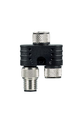
アクセサリー: Yアダプター BNS-Y-11
アクセサリー: Yアダプター BNS-Y-02
5 立ち上げと保全
セーフティコンポーネントの安全機能をテストする必要があります。正しく取り付けられ、適切に使用されていれば、セーフティスイッチはメンテナンスフリーです。通常の目視及び機能テストに加えて、以下のチェックを推奨します。
- セーフティスイッチとアクチュエーターの取り付けチェック
- ケーブルコネクターが確実に取り付けられているか確認
- システムに埃や汚れ(特に金属片)はないか。
- 例えば予備のアクチュエータを使うなどする無効化に対する保護のために、そしてガードの無効化防止のために、適切な方策を講じなければなりません。
- 破損、故障の場合は交換してください。
6 取り外し・廃棄
6.1 取り外し
セーフティスイッチの取り外しは非通電状態で行わなければなりません。
6.2 廃棄処分
- セーフティスイッチは国家規格や法規に従って、適切な措置により廃棄しなければなりません。
| EU Declaration of Conformity |  |
| Original | K.A. Schmersal GmbH & Co. KG Möddinghofe 30 42279 Wuppertal Germany Internet: www.schmersal.com |
| Declaration: | We hereby certify that the hereafter described components both in their basic design and construction conform to the applicable European Directives. |
| Name of the component: | BNS 260 |
| Type: | See ordering code |
| Description of the component: | Coded safety-sensor with magnetic operating principle in combination with the SRB(-E) / PROTECT-SELECT / PSC1 safety-monitoring modules from Schmersal or an equivalent safety-oriented control system fulfilling the requirements of the EN 60947-5-3. |
| Relevant Directives: | Machinery Directive | 2006/42/EC |
| RoHS-Directive | 2011/65/EU |
| Applied standards: | EN 60947-5-3:2013 EN ISO 14119:2013 |
| Person authorised for the compilation of the technical documentation: | Oliver Wacker Möddinghofe 30 42279 Wuppertal |
| Place and date of issue: | Wuppertal, January 28, 2022 |
 |
| Authorised signature Philip Schmersal Managing Director |
| UK Declaration of Conformity | |
| Company: | K.A. Schmersal GmbH & Co. KG Möddinghofe 30 42279 Wuppertal Germany Internet: www.schmersal.com |
| Declaration: | We hereby, under sole responsibility, certify that the hereafter described components both in their basic design and construction conform to the relevant statutory requirements, regulations and designated standards of the United Kingdom. |
| Name of the component: | BNS 260 |
| Type: | See ordering code |
| Description of the component: | Coded safety-sensor with magnetic operating principle in combination with the SRB(-E) / PROTECT-SELECT / PSC1 safety-monitoring modules from Schmersal or an equivalent safety-oriented control system fulfilling the requirements of the EN 60947-5-3. |
| Relevant legislation: | Supply of Machinery (Safety) Regulations | 2008 |
| The Restriction of the Use of Certain Hazardous Substances in Electrical and Electronic Equipment Regulations | 2012 |
| Designated standards: | EN 60947-5-3:2013 EN ISO 14119:2013 |
| UK-Importer / Person authorised for the compilation of the technical documentation: | Schmersal UK Ltd. Paul Kenney Unit 1, Sparrowhawk Close Enigma Business Park Malvern, Worcestershire, WR14 1GL |
| Place and date of issue: | Wuppertal, June 17, 2022 |
|
| Authorised signature Philip Schmersal Managing Director |
シュメアザー株式会社, 〒222-0033 横浜市港北区新横浜3-9-5, 新横浜第3東昇ビル
データと詳細は完全にチェックされました。画像は元の画像と異なる場合があります。技術的なデータはマニュアルで見られます。技術的に変更されたり、エラーの可能性があります。
Generated on 2025/08/01 21:41