BNS 33-02Z-2187 3,0M

BNS 33-02Z-2187 3,0M
- Kunststofbehuizing
- Verdekte inbouw mogelijk
- Ongevoelig voor zijdelingse afwijking
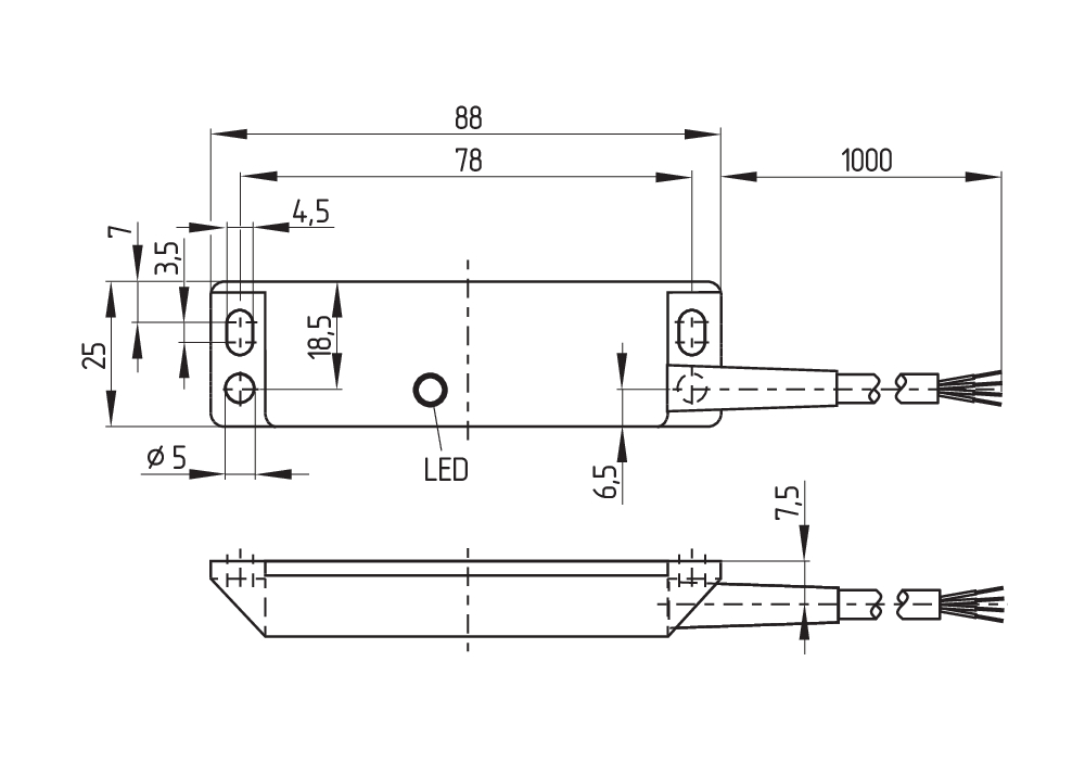
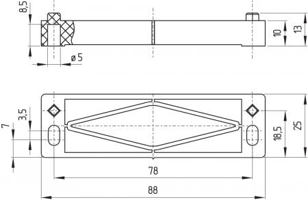
- 88 mm x 25 mm x 13 mm
- Lange levensduur
- geen mechanische slijtage
- Ongevoelig voor vervuiling
Bestelvoorbeeld
| Typebenaming van het product |
BNS 33-02Z-2187 3,0M |
| Artikelnummer (bestelnummer) |
101142030 |
| EAN (Europees Artikel Nummer) |
4030661123813 |
Certificeringen - Voorschriften
| Certificaten |
TÜV cULus |
Algemene gegevens
| Voorschriften |
BG-GS-ET-14 EN IEC 60947-5-3 |
| Codeerniveau volgens EN ISO 14119 |
gering |
| Werkingsprincipe |
magnetisch |
| Inbouwcondities (mechanische) |
niet vlak |
| Materiaal van de behuizing |
Kunststof, glasvezelversterkte thermoplast |
| Brutogewicht |
130 g |
Algemene gegevens - Eigenschappen
| Voorwaarde voor de veiligheidsmodule |
Ja |
| Aantal verbreekcontacten |
2 |
Classificatie
| Normen, voorschriften: |
EN ISO 13849-1 |
| Gebruiksduur |
20 Jaar (Jaren) |
Mechanische gegevens
| Bedienelement |
Magneet |
| Bewegingsrichting |
Frontaal ten opzichte van de actieve zijde |
Mechanische gegevens - schakelafstanden volgens EN IEC 60947-5-3
| Verzekerde inschakelafstand "IN" Sao |
5 mm 8 mm |
| Verzekerde uitschakelafstand "UIT" Sar |
15 mm 18 mm |
| Opmerking (herhalingsnauwkeurigheid R) |
Herhalingsnauwkeurigheid R ≤ 0,1 x Sao |
Mechanische gegevens - Aansluittechniek
| Lengte van de kabel |
3 m |
| aansluitwijze |
Kabel |
| Aderdoorsnede |
0,25 mm2 |
| Aderdoorsnede |
23 AWG |
| Materiaal van de kabelmantel |
PVC |
Mechanische gegevens - Afmetingen
| Lengte van de sensor |
13 mm |
| Breedte van de sensor |
88 mm |
| Hoogte van de sensor |
25 mm |
Omgevingsvoorwaarden
| Afdichtingsgraad |
IP67 |
| Ambient temperature |
-25 ... +70 °C |
| Storage and transport temperature |
-25 ... +70 °C |
| Trillingsvastheid volgens EN 60068-2-6 |
10…55 Hz, amplitude 1 mm |
| schokbestendig |
30 g / 11 ms |
Elektrische gegevens
| Schakelstroom; maximum |
0,25 A |
| Schakelvermogen, maximum |
0,24 W |
| Schakelfrequentie, maximum |
5 Hz |
Elektrische gegevens - Digitale uitgang
| Uitvoering |
Diverse, Reed-contact |
Leveringsomvang
| Leveringsomvang |
Actuator must be ordered separately. |
Toebehoren
| Aanbeveling (bediensleutel) |
BPS 33-2326 BPS 33 |
Opmerking
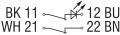
| Opmerking (algemeen) |
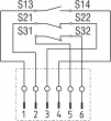
Afbeelding van de contactsymbolen bij gesloten beschermvoorziening. De contactconfiguraties voor versies met of zonder LED zijn identiek. |
Taalfilter
Datasheet
Bedieningshandleiding en conformiteitsverklaring
UL-certificaat
SISTEMA-VDMA-bibliotheek/library
Download de nieuwste versie van Adobe Reader
Foto van het product (individuele catalogusfoto)
Maatschets basistoestel
Contactschema

Karakteristiek diagram

Table of Contents
- 1 About this document
- 1.1 Function
- 1.2 Target group of the operating instructions: authorised qualified personnel
- 1.3 Explanation of the symbols used
- 1.4 Appropriate use
- 1.5 General safety instructions
- 2 Product description
- 2.1 Ordering code
- 2.2 Special versions
- 2.3 Purpose
- 2.4 Warning about misuse
- 2.5 Exclusion of liability
- 3 Technical Data
- 4 Mounting
- 4.1 General mounting instructions
- 4.2 Dimensions
- 4.3 Axial misalignment
- 4.4 Adjustment
- 5 Electrical connection
- 5.1 General information for electrical connection
- 5.2 Contact Options
- 5.3 Connector accessories
- 6 Set-up and maintenance
- 7 Disassembly and disposal
- 7.1 Disassembly
- 7.2 Disposal
1 About this document
1.1 Function
This document provides all the information you need for the mounting, set-up and commissioning to ensure the safe operation and disassembly of the switchgear. The operating instructions enclosed with the device must always be kept in a legible condition and accessible.
1.2 Target group of the operating instructions: authorised qualified personnel
All operations described in the operating instructions manual must be carried out by trained specialist personnel, authorised by the plant operator only.
Please make sure that you have read and understood these operating instructions and that you know all applicable legislations regarding occupational safety and accident prevention prior to installation and putting the component into operation.
The machine builder must carefully select the harmonised standards to be complied with as well as other technical specifications for the selection, mounting and integration of the components.
The information contained in this operating instructions manual is provided without liability and is subject to technical modifications.
1.3 Explanation of the symbols used
- Information, hint, note: This symbol is used for identifying useful additional information.
- Caution: Failure to comply with this warning notice could lead to failures or malfunctions.
Warning: Failure to comply with this warning notice could lead to physical injury and/or damage to the machine.
1.4 Appropriate use
The Schmersal range of products is not intended for private consumers.
The products described in these operating instructions are developed to execute safety-related functions as part of an entire plant or machine. It is the responsibility of the manufacturer of a machine or plant to ensure the correct functionality of the entire machine or plant.
The safety switchgear must be exclusively used in accordance with the versions listed below or for the applications authorised by the manufacturer. Detailed information regarding the range of applications can be found in the chapter "Product description".
1.5 General safety instructions
The user must observe the safety instructions in this operating instructions manual, the country specific installation standards as well as all prevailing safety regulations and accident prevention rules.
- Further technical information can be found in the Schmersal catalogues or in the online catalogue on the Internet: products.schmersal.com.
2 Product description
2.1 Ordering code
| Product type description: BNS 33-(1)Z(2)-(3)-(4) |
| (1) | |
| 02 | 2 NC contact |
| 11 | 1 NO contacts/1 NC contact |
| 12 | 1 NO contact/2 NC contacts |
| (2) | |
| without | without LED switching conditions display |
| G | with LED switching conditions display |
| (3) | |
| without | with cable |
| ST | with connector M8 |
| (4) | |
| 2187 | Individual contact outlet |
| 2187-10 | Individual contact outlet with LED |
| 2237 | Actuation from cable direction |
2.2 Special versions
For special versions, which are not listed in the ordering code, these specifications apply accordingly, provided that they correspond to the standard version.
2.3 Purpose
The safety sensor BNS 33-…-2187/-2363 is designed to monitor the position of movable safety guards in safety circuits to EN ISO 14119 and EN 60947-5-3. To actuate the safety sensors, only the BPS 33 actuators can be used, conventional magnets are not suitable.
The safety switches are used for applications, in which the hazardous situation is terminated without delay when the safety guard is opened.
- The safety switchgears are classified according to EN ISO 14119 as type 4 interlocking devices.
Only the entire system consisting of the safety sensor (BNS 33), the actuator (BPS 33) and the safety-monitoring module (SRB) meets the requirements of the standard EN 60947-5-3.
- The user must evaluate and design the safety chain in accordance with the relevant standards and the required safety level.
- The entire concept of the control system, in which the safety component is integrated, must be validated to the relevant standards.
2.4 Warning about misuse
- In case of improper use or manipulation of the safety switchgear, personal hazards or damages to machinery or plant components cannot be excluded. There are no residual risks, provided that the safety instructions as well as the instructions regarding mounting, commissioning, operation and maintenance are observed.
2.5 Exclusion of liability
We shall accept no liability for damages and malfunctions resulting from defective mounting or failure to comply with the operating instructions manual. The manufacturer shall accept no liability for damages resulting from the use of unauthorised spare parts or accessories.
For safety reasons, invasive work on the device as well as arbitrary repairs, conversions and modifications to the device are strictly forbidden, the manufacturer shall accept no liability for damages resulting from such invasive work, arbitrary repairs, conversions and/or modifications to the device.
3 Technical Data
Certificeringen - Voorschriften
| Certificaten |
TÜV cULus |
Algemene gegevens
| Voorschriften |
BG-GS-ET-14 EN IEC 60947-5-3 |
| Codeerniveau volgens EN ISO 14119 |
gering |
| Werkingsprincipe |
magnetisch |
| Inbouwcondities (mechanische) |
niet vlak |
| Materiaal van de behuizing |
Kunststof, glasvezelversterkte thermoplast |
| Brutogewicht |
130 g |
Algemene gegevens - Eigenschappen
| Voorwaarde voor de veiligheidsmodule |
Ja |
| Aantal verbreekcontacten |
2 |
Classificatie
| Normen, voorschriften: |
EN ISO 13849-1 |
| Gebruiksduur |
20 Jaar (Jaren) |
Mechanische gegevens
| Bedienelement |
Magneet |
| Bewegingsrichting |
Frontaal ten opzichte van de actieve zijde |
Mechanische gegevens - schakelafstanden volgens EN IEC 60947-5-3
| Verzekerde inschakelafstand "IN" Sao |
5 mm 8 mm |
| Verzekerde uitschakelafstand "UIT" Sar |
15 mm 18 mm |
| Opmerking (herhalingsnauwkeurigheid R) |
Herhalingsnauwkeurigheid R ≤ 0,1 x Sao |
Mechanische gegevens - Aansluittechniek
| Lengte van de kabel |
3 m |
| aansluitwijze |
Kabel |
| Aderdoorsnede |
0,25 mm2 |
| Aderdoorsnede |
23 AWG |
| Materiaal van de kabelmantel |
PVC |
Mechanische gegevens - Afmetingen
| Lengte van de sensor |
13 mm |
| Breedte van de sensor |
88 mm |
| Hoogte van de sensor |
25 mm |
Omgevingsvoorwaarden
| Afdichtingsgraad |
IP67 |
| Ambient temperature |
-25 ... +70 °C |
| Storage and transport temperature |
-25 ... +70 °C |
| Trillingsvastheid volgens EN 60068-2-6 |
10…55 Hz, amplitude 1 mm |
| schokbestendig |
30 g / 11 ms |
Elektrische gegevens
| Schakelstroom; maximum |
0,25 A |
| Schakelvermogen, maximum |
0,24 W |
| Schakelfrequentie, maximum |
5 Hz |
Elektrische gegevens - Digitale uitgang
| Uitvoering |
Diverse, Reed-contact |
Note about the safety classification
For 2-channel use with suitable logic, can be used up to Cat. 4 / PL e.

(Determined values can vary depending on the application-specific parameters hop, dop and tcycle as well as the load.)
If multiple safety components are wired in series, the Performance Level to EN ISO 13849-1 will be reduced due to the restricted error detection under certain circumstances.
4 Mounting
4.1 General mounting instructions
- During fitting, the requirements of EN ISO 14119 must be observed.
- Fitting is only authorised in a de-energised condition
- Do not use the sensor and the actuator as a mechanical backstop
- Any mounting position, provided that the active surfaces are opposite
- Do not subject the safety sensor and actuator to extreme vibrations and shocks
To avoid any interference inherent to this kind of system and any reduction of the switching distances, please observe the following guidelines:
- Ensure the safety sensor is mounted on a flat surface
- Do not install the safety sensor and the actuator in strong magnetic fields
- If possible, do not mount the sensor and the actuator on ferromagnetic material. Otherwise, the following variations of the switching distances may be expected: A distance of 0…5 mm from the mounting surface to the ferromagnetic material: switching distance is only approx. 40 % of the original switching distance; A distance of 5…8 mm: approx. 80 % of the original switching distance; > 10 mm: no change (use spacer BN 31/33). The use of non-magnetic fixing screws is recommended also.
- Keep away from metal chips
- The mounting distance between two sensors should always be at least 50 mm
- The actuator must be permanently fitted to the safety guards and protected against displacement by suitable measures (tamperproof screws, gluing, drilling of the screw heads).
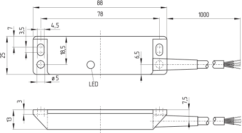
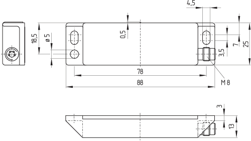
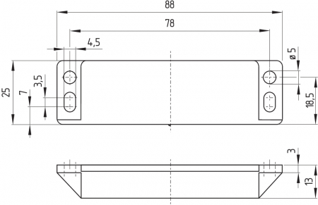
4.2 Dimensions
All measurements in mm.
Safety sensor with cable
Safety sensor with connector
Actuator
Spacer
4.3 Axial misalignment
A horizontal and vertical misalignment of the safety sensor and the actuator is tolerated. The possible misalignment depends on the distance of the active surfaces of the sensor and the actuator. The sensor remains active within the tolerance range.
The specified switching distances refer to opposedly mounted safety sensors and actuators.
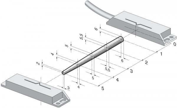
| Assured switching distance: | sao = | 5 mm 8 mm (ordering suffix -2363) |
| Assured switch-off distance: | sar = | 15 mm |
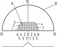
| Key | |
|---|---|
| A | Base position area (sensor actuated, release) |
| B | Switch-off area (at the latest at this point, all reed contacts are not actuated) |
4.4 Adjustment
- Recommended Adjustment
Align the safety sensor and actuator at a distance of 0.5 x sao.
Align the central markings of the safety sensor and the actuator with each other. The LED can only be used as rough setting tool. The correct functionality of both safety channels must be checked by means of the connected safety-monitoring module.
5 Electrical connection
5.1 General information for electrical connection
- The electrical connection may only be carried out by authorised personnel in a de-energised condition.
The safety sensors must be wired in accordance with the wire colours or the pin configuration.
The correct function of the connected safety sensor must always be checked.
- Information for the selection of suitable safety-monitoring modules can be found in the Schmersal catalogues or in the online catalogue on the Internet: products.schmersal.com
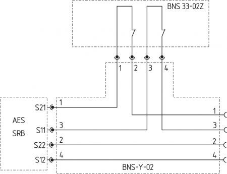
Connecting multiple safety sensors to one SRB safety-monitoring module is technically possible. To connect multiple safety sensors, their NO contacts are wired in parallel and all NC contacts that are relevant to safety in series (check authorisation). The Protect-IE-11 or -02 or PROTECT-PE-11 (-AN) or -02 input expander module can be used to connect up to 4 safety sensors with NC/NC or NC/NO contacts.
Safety sensors equipped with LED's shall not be wired in series, except for the PROTECT-IE or PROTECT-PE input expander module. If the LED's of the series-wired safety sensors are in the NC paths, the luminosity of the LED's is highly reduced and the increased voltage drop will possibly cause the voltage dropping below the minimum input voltage of the downstream safety-monitoring module.
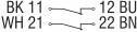
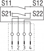
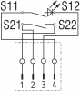
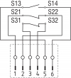
5.2 Contact Options
The contact position shows the actuated sensor function when the safety guard is closed. For safety sensors with LED, the LED is illuminated when the safety guard is closed.
| Safety contacts: | -02Z: | S11-S12 and S21-S22 |
| -12Z: | S21-S22 and S31-S32 | |
| Signalling contact: | -12Z: | S13-S14 |
| BNS 33-02Z-2187 | BNS 33-02ZG-2187 |
|---|---|
 |  |
| BNS 33-02ZST-2187 | BNS 33-02ZGST-2187 | |
|---|---|---|
 |  |  |
| BNS 33-12Z-2187 BNS 33-12Z-2363 | BNS 33-12ZG-2187 | BNS 33-12ZG-2187-10 |
|---|---|---|
 |  |  |
| BNS 33-12Z-LST-2187 | BNS 33-12Z-2363 | ||
|---|---|---|---|
 |  |  |  |
5.3 Connector accessories
| M8, 4-pole, with screw terminal | 2 m | 5 m | 10 m | |||
|---|---|---|---|---|---|---|
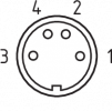 | 1 | BN | straight | 103011340 | 103007356 | - |
| 2 | WH | |||||
| 3 | BU | angled | 101210557 | 101210559 | - | |
| 4 | BK | |||||
Accessory: Y-adapter BNS-Y-02
6 Set-up and maintenance
The safety function of the safety components must be tested. In the case of correct installation and adequate use, the safety switchgear features maintenance-free functionality. A regular visual inspection and functional test, including the following steps, is recommended:
- Check fixation of the safety switch and the actuator.
- Fitting and integrity of the cable connections.
- The system is free of dirt and soiling (in particular metal chips).
- Adequate measures must be taken to ensure protection against tampering either to prevent tampering of the safety guard, for instance by means of replacement actuators.
- Damaged or defective components must be replaced.
7 Disassembly and disposal
7.1 Disassembly
The safety switchgear must be disassembled in a de-energised condition only.
7.2 Disposal
- The safety switchgear must be disposed of in an appropriate manner in accordance with the national prescriptions and legislations.
Schmersal Belgium, Nieuwlandlaan 73, 3200 Aarschot
De genoemde gegevens en informatie zijn zorgvuldig gecontroleerd. Afbeeldingen kunnen afwijken van het origineel. Verdere technische gegevens zijn te vinden in de handleiding. Technische wijzigingen en fouten voorbehouden.
Gegenereerd op 22/06/2024 04:43