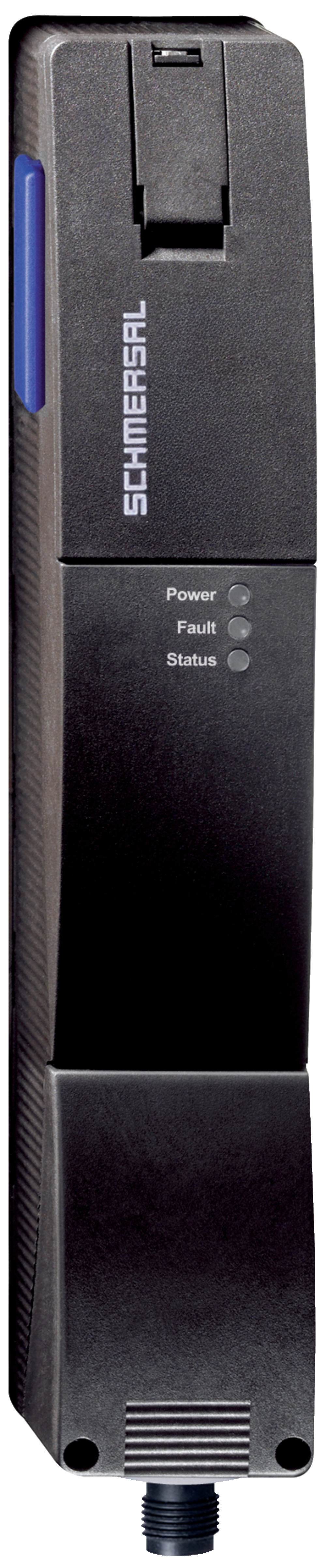
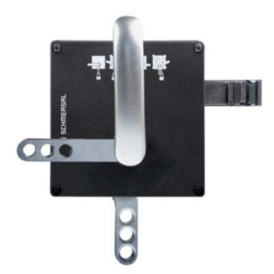
AZM201Z-I2-ST2-T-SD2P
- 带RFID技术的重复单独编码
- 通电开锁
- 锁定监控
- 热塑外壳
- 传感器链最大长度 200 m
- 31串联传感器的自我监控
- 使用RFID技术进行编码,符合ISO 14119
- 3 运行状态指示灯
- 传感器技术允许操动件和门锁之间,允许垂直± 5 mm, 水平± 1,5 mm的偏差
- 适合滑动和铰链门
- 智能诊断
- 手动解锁
- 防护等级 IP66, IP67
- 高持紧力 2000 N
- 对称构造形式,装配在40mm型材上
- OSSD 安全输出
- 适用于改造的紧急逃逸/紧急解锁功能
订货数据
| 型号 |
AZM201Z-I2-ST2-T-SD2P |
| 商品编号(订购编号) |
103013492 |
| EAN(欧洲商品编号) |
4030661493350 |
| eCl@aa number,版本:12.0 |
27-27-26-03 |
| eCl@aa number,版本:11.0 |
27-27-26-03 |
| eCl@aa number,版本:9.0 |
27-27-26-03 |
| ETIM 编号,7.0 版 |
EC002593 |
| ETIM 编号,6.0 版 |
EC002593 |
许可 - 标准
| 证书 |
TÜV cULus FCC IC UKCA ANATEL |
总体数据
| 标准型 |
EN ISO 13849-1 EN ISO 14119 EN IEC 60947-5-3 EN IEC 61508 |
| 编码 |
单独编码,多次示教 |
| 编码等级,依据EN ISO 14119 |
高 |
| 工作原理 |
RFID |
| 频段 RFID |
125 kHz |
| 发射器输出 RFID, 最大植 |
-6 dBm |
| 外壳材料 |
玻璃纤维,加强型热塑塑料 |
| 风险持续期,最大 |
200 ms |
| 响应时间, 通过执行机构关闭安全输出,最大 |
100 ms |
| 响应时间,通过安全输入关闭安全输出,最大值 |
1.5 ms |
| 毛重 |
595 g |
总体数据 - 产品特性
| 通电解锁 |
是 |
| 电磁安全锁,受监控 |
是 |
| 串联诊断 |
是 |
| 手动解锁 |
是 |
| 短路检测 |
是 |
| 交叉电路检测 |
是 |
| 串联连接 |
是 |
| 安全功能 |
是 |
| 整个系统检测,状态 |
是 |
| 安全触点数量 |
2 |
| 传感器串联数量 |
31 |
安全评估
| 标准型 |
EN ISO 13849-1 EN IEC 61508 |
安全评估 - 联锁
| 性能水平,最高 |
e |
| 类别 |
4 |
| PFH值 |
1.90 x 10⁻⁹ /h |
| PFD值 |
1.60 x 10⁻⁴ |
| 安全完整性等级 (SIL),停止 0,适用于以下应用 |
3 |
| 任务时间 |
20 年 |
机械参数
| 机械寿命,最少 |
1,000,000 操作 |
| 保持力 FZh 按照 EN ISO 14119 |
2,000 N |
| 注意 (合型力 FZh) |
1,000 N 当使用↲AZ/ AZ/AZM201-B30操动件,用于室内. |
| 锁紧力 Fmax, 最大 |
2,600 N |
| 注意 (合型力 Fmax) |
1,300 N 当使用↲AZ/ AZ/AZM201-B30操动件,用于室内. |
| 锁定力 |
30 N |
| 操动速度,最大 |
0.2 m/s |
| 固定螺丝类型 |
2x M6 |
| 固定螺钉的紧锢力矩, 最大值 |
8 Nm |
| 箱盖紧固螺钉的拧紧扭矩,最低 |
0.7 Nm |
| 箱盖紧固螺钉的拧紧扭矩,最大 |
1 Nm |
| 注意 |
Torx T10 |
机械参数 - 连接技术
| 传感器链长度,最大 |
200 m |
| 注意 (传感器链长度) |
根据输出电流,电缆长度和电缆截面会改变电压降 |
| 注意 (串联连接) |
设备数量不限,oberserve 外部线路熔断,最多可连接 31 台设备。在串行诊断 SD 的情况下,最多可连接 31 台设备 |
| 连接器 |
连接器M12,8芯 |
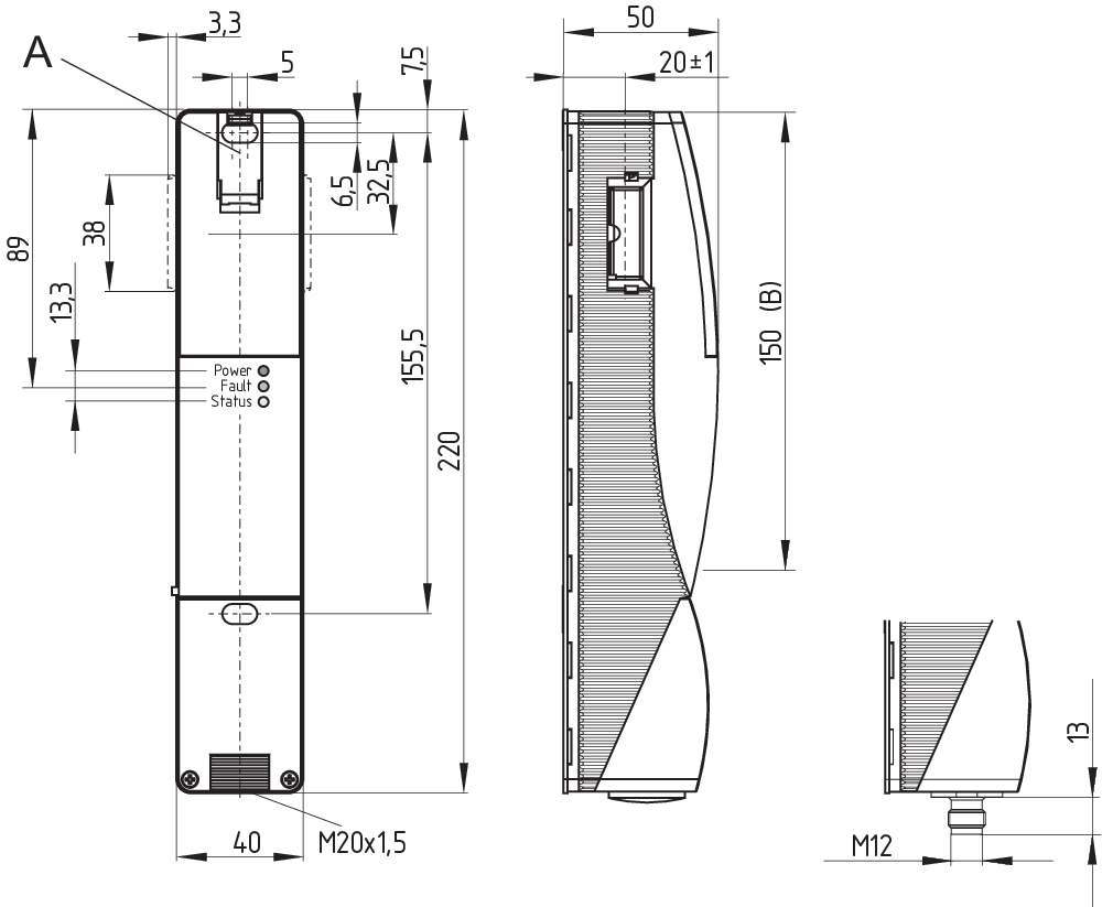
机械参数 - 尺寸
| 传感器长度 |
50 mm |
| 传感器宽度 |
40 mm |
| 传感器高度 |
220 mm |
环境条件
| 防护等级 |
IP66 IP67 |
| 工作环境温度 |
-25 ... +60 °C |
| 储存和运输温度 |
-25 ... +85 °C |
| 最大相对湿度 |
93 % |
| 注(相对湿度) |
无冷凝 不结冰 |
| 抗振动 |
10 ... 150 Hz,振幅 .35 mm |
| 耐冲击 |
30 g / 11 ms |
| 防护等级 |
III |
| 最大允许安装海拔高度 |
2,000 m |
环境条件 - 绝缘值
| 额定绝缘电压 Ui |
32 VDC |
| 额定冲击耐受电压 Uimp |
0.8 kV |
| 过电压级别 |
III |
| 污染等级 |
3 |
电气参数
| 工作电压 |
24 VDC -15 % / +10 % (稳定PELV电源) |
| 空载电源电流 I0, 典型 |
50 mA |
| 磁铁接通时的电流消耗,平均值 |
200 mA |
| 磁铁接通时的电流消耗, 峰值 |
700 mA / 100 ms |
| 额定工作电压 |
24 VDC |
| 工作电流 |
1,200 mA |
| 要求额定短路电流 |
100 A |
| 外部电线和设备保险丝额定值 |
2 A gG |
| 准备就绪时间,最大 |
4,000 ms |
| 转换频率,最大 |
1 Hz |
电气参数 - 线圈控制
| 指定, 线圈控制 |
IN |
| 开关阈值 |
-3 V … 5 V (Low) 15 V … 30 V (High) |
| 磁铁闭合时间 |
100 % |
| 测试脉冲持续时间, 最大 |
5 ms |
| 测试脉冲间隔, 最低限度 |
40 ms |
| 分类 ZVEI CB24I,接收器 |
C0 |
| 分类 ZVEI CB24I,信号源 |
C1 C2 C3 |
电子参数 - 安全数字输入
| 指定,安全输入 |
X1 和 X2 |
| 开关阈值 |
−3 V … 5 V (Low) 15 V … 30 V (High) |
| 24V时,电流消耗 |
5 mA |
| 测试脉冲持续时间, 最大 |
1 ms |
| 测试脉冲间隔, 最低限度 |
100 ms |
| 分类 ZVEI CB24I,接收器 |
C1 |
| 分类 ZVEI CB24I,信号源 |
C1 C2 C3 |
电气参数 - 安全数字输出
| 指定,安全输出 |
Y1和Y2 |
| 额定工作电流(安全输出) |
250 mA |
| 控制元件的设计 |
短路保护,P型 |
| 电压降 Ud, 最大电压降 Ud, 最大 |
2 V |
| 泄漏电流 Ir, 最大植 |
0.5 mA |
| 电压,应用类别 DC-13 |
24 VDC |
| 电流,应用类别 DC-13 |
0.25 A |
| 测试脉冲间隔,典型 |
1000 ms |
| 测试脉冲持续时间, 最大 |
0.5 ms |
| 分类 ZVEI CB24I,信号源 |
C2 |
| 分类 ZVEI CB24I,接收器 |
C1 C2 |
电子参数 - 串行诊断SD
| 指定,串联诊断SD |
OUT |
| 工作电流 |
150 mA |
| 控制元件的设计 |
短路保护,P型 |
| 布线电容 |
50 nF |
状态显示
| 注 (LED开关状态显示) |
工作状态:LED绿色 错误 / 功能故障:LED红色 供电电压 UB:LED 绿色 |
引脚分配
| PIN 1 |
A1 电源电压 UB |
| PIN 2 |
X1 安全输入 1 |
| PIN 3 |
A2 GND |
| PIN 4 |
Y1 安全输出 1 |
| PIN 5 |
OUT 串行诊断输出 |
| PIN 6 |
X2 安全输入 2 |
| PIN 7 |
Y2 安全输出 2 |
| PIN 8 |
IN 串行诊断输入 |
发货范围
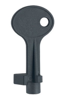
| 发货范围 |
操动件#必须单独订购. AZM201用的三角钥匙 |
附件
| 建议(操动件) |
AZ/AZM201-B1 AZ/AZM201-B30 |
注意
| 注(通用) |
只要操动件保持插入在电磁安全锁中,已解锁的防护门会重新锁定。在这种情况下,安全输出将重新启用,因此不能打开安全防护装置。 |
语言条件
数据表
操作说明书(补充页/快速指南)
操作指南及符合性声明(短篇)
IC-Zertifikat
手册
SISTEMA-VDMA 数据库
下载最新版本的Adobe Reader
产品图片(单独目录照片)
尺寸图 基本组件
Video ID: SD-Interface-Mr-Safety

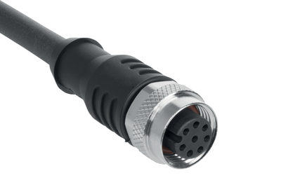
103011415 A-K8P-M12-S-G-2,5M-BK-2-X-A-4-69
- 2.5 m
- 带线
- 8-芯

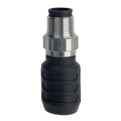
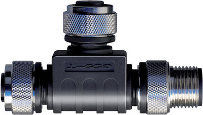
101209414 CSS-Y-A-8P
- 带串联诊断的串联接线附件
- 连接器提供安全通道工作电压。
103008718 CSS-Y-A-8P-VA
- 带串联诊断的串联接线附件
- 连接器提供安全通道工作电压。
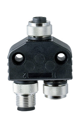
103009361 SD-Y-POWER
- 带串联诊断的串联接线附件
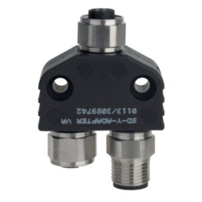
103009362 SD-Y-POWER VA
- 带串联诊断的串联接线附件
101190026 CSS-T
- 带串联诊断的串联接线附件
- 为了 传感器

101190025 CSS-T-A
- 带串联诊断的串联接线附件
- 为了 CSS 34

101209416 CSS-Y-8P
- 带串联诊断的串联接线附件
103008717 CSS-Y-8P-VA
- 带串联诊断的串联接线附件

103009970 SRB-E-201LC
- STOP 0 功能
- 1 oder 2通道控制
- 启动按钮 / 自启动
- 2 安全输出 2 A
- 1 信号输出

103007672 SRB-E-301ST
- STOP 0 功能
- 1 oder 2通道控制
- 启动按钮 / 自启动
- 1
- 3 安全触点

103009973 SRB-E-204ST
- STOP 0 功能
- 监控4个传感器
- 启动按钮 / 自启动
- 2 安全输出
- 4 信号输出
103013501 AZ/AZM201-B30-LTAG1
- 左铰链门
- 带,有
- 铰链门用操动件
- 简单直观的操作
- 突出的操动件无伤害风险
- 无需额外门把手
- 不会刺出到门打开的区域
103013502 AZ/AZM201-B30-RTAG1
- 右铰链门
- 带,有
- 铰链门用操动件
- 简单直观的操作
- 突出的操动件无伤害风险
- 无需额外门把手
- 不会刺出到门打开的区域
103013498 AZ/AZM201-B30-LTAG1P1
- 左铰链门
- 带手柄和紧急逃逸手柄
- 铰链门用操动件
- 简单直观的操作
- 突出的操动件无伤害风险
- 无需额外门把手
- 不会刺出到门打开的区域
103013497 AZ/AZM201-B30-RTAG1P1
- 右铰链门
- 带手柄和紧急逃逸手柄
- 铰链门用操动件
- 简单直观的操作
- 突出的操动件无伤害风险
- 无需额外门把手
- 不会刺出到门打开的区域
103013500 AZ/AZM201-B30-LTAG1P1-SZ
- 左铰链门
- 带手柄和紧急逃逸手柄
- 带集成上锁标签
- 铰链门用操动件
- 简单直观的操作
- 突出的操动件无伤害风险
- 无需额外门把手
- 不会刺出到门打开的区域
103013499 AZ/AZM201-B30-RTAG1P1-SZ
- 右铰链门
- 带手柄和紧急逃逸手柄
- 带集成上锁标签
- 铰链门用操动件
- 简单直观的操作
- 突出的操动件无伤害风险
- 无需额外门把手
- 不会刺出到门打开的区域
103026322 AZ/AZM201-B30-LTAG1P20-SZ
- 带集成上锁标签
- 无需额外门把手
- 左铰链门
- 简单直观的操作
- 不会刺出到门打开的区域
- 铰链门用操动件
- 带手柄和紧急逃逸手柄
- 突出的操动件无伤害风险
103026321 AZ/AZM201-B30-RTAG1P20-SZ
- 带集成上锁标签
- 无需额外门把手
- 右铰链门
- 简单直观的操作
- 不会刺出到门打开的区域
- 铰链门用操动件
- 带手柄和紧急逃逸手柄
- 突出的操动件无伤害风险
103015820 AZ/AZM201-B30-LTAG1P30
- 左铰链门
- 带,有
- 铰链门用操动件
- 简单直观的操作
- 突出的操动件无伤害风险
- 无需额外门把手
- 不会刺出到门打开的区域
103015823 AZ/AZM201-B30-RTAG1P30
- 右铰链门
- 带,有
- 铰链门用操动件
- 简单直观的操作
- 突出的操动件无伤害风险
- 无需额外门把手
- 不会刺出到门打开的区域
103015821 AZ/AZM201-B30-LTAG1P31
- 左铰链门
- 带手柄和紧急逃逸手柄
- 铰链门用操动件
- 简单直观的操作
- 突出的操动件无伤害风险
- 无需额外门把手
- 不会刺出到门打开的区域

103015824 AZ/AZM201-B30-RTAG1P31
- 右铰链门
- 带手柄和紧急逃逸手柄
- 铰链门用操动件
- 简单直观的操作
- 突出的操动件无伤害风险
- 无需额外门把手
- 不会刺出到门打开的区域
103015822 AZ/AZM201-B30-LTAG1P31-SZ
- 左铰链门
- 带手柄和紧急逃逸手柄
- 带集成上锁标签
- 铰链门用操动件
- 简单直观的操作
- 突出的操动件无伤害风险
- 无需额外门把手
- 不会刺出到门打开的区域
103015825 AZ/AZM201-B30-RTAG1P31-SZ
- 右铰链门
- 带手柄和紧急逃逸手柄
- 带集成上锁标签
- 铰链门用操动件
- 简单直观的操作
- 突出的操动件无伤害风险
- 无需额外门把手
- 不会刺出到门打开的区域

103013493 AZ/AZM201-B1-LT
- 左铰链门
- 带复位弹簧的操动件
- 滑动门用操动件
- 偏差最大到过行程5 mm

103013496 AZ/AZM201-B1-LTP0
- 左铰链门
- 带,有 紧急逃逸
- 带复位弹簧的操动件
- 滑动门用操动件
- 偏差最大到过行程5 mm
103013494 AZ/AZM201-B1-RT
- 右铰链门
- 带复位弹簧的操动件
- 滑动门用操动件
- 偏差最大到过行程5 mm
103013495 AZ/AZM201-B1-RTP0
- 右铰链门
- 带,有 紧急逃逸
- 带复位弹簧的操动件
- 滑动门用操动件
- 偏差最大到过行程5 mm

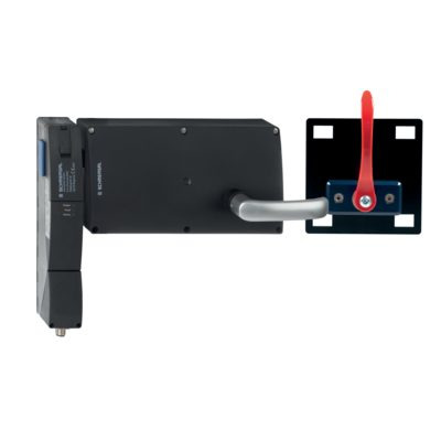
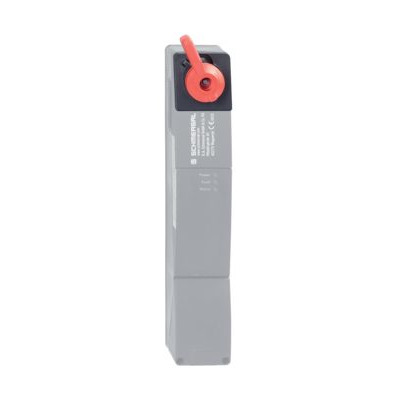
103004966 RF-AZM201-T
- 紧急逃逸改装套件
- 电磁安全锁AZM201的后续功能扩展
103003543 RF-AZM201-N
- 紧急解锁改装套件
- 电磁安全锁AZM201的后续功能扩展
- 可选的铅封
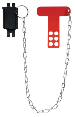
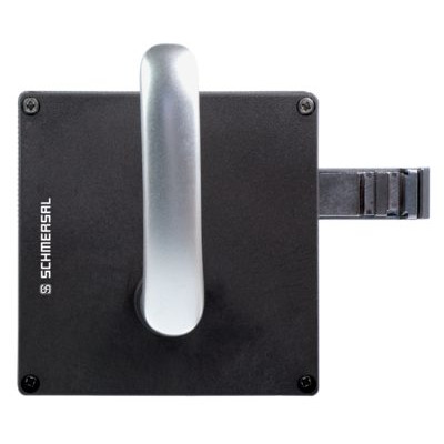
103051655 SZ201-1
- 安装在危险区内外均可
- 为防止意外关闭,比如在维修时
- 复杂工厂环境
- 防止开关操作
- 带6圆形孔的停工标签

101194438 停工上锁标签 SZ 200
- 带5圆形孔的停工标签
- 安装在危险区内外均可
- 为防止意外关闭,比如在维修时
- 复杂工厂环境
- 防止开关操作
103001074 RF-AZ/AZM201-B30-SZ
- 允许添加 集成上锁标签
- 适用于可用的B30操纵系统
- 带3圆形孔的停工标签
- 复杂工厂环境
- 防止开关操作
101166329 TFI-010
- 预定位
- 操动件独立于对准机构
- 操动件插入和拉出顺畅
101166328 TFA-010
- 预定位
- 操动件独立于对准机构
- 操动件插入和拉出顺畅
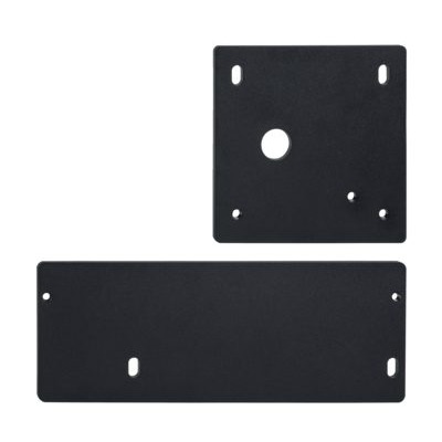
101214126 MP-AZ/AZM201/BDF200-AZ/AZM201-B30
- 可方便快捷安装的安装底板
- 金属,粉末喷涂
- 适用于左右铰链门
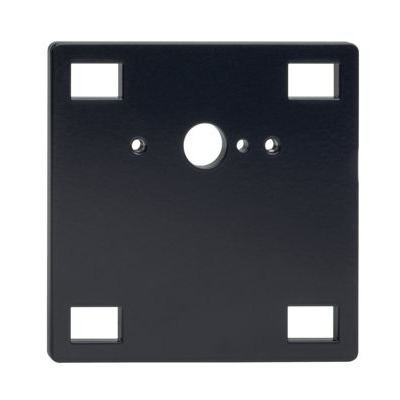
101185694 MP-AZ/AZM201-P20
- 可方便快捷安装的安装底板
- 金属,粉末喷涂
- 适用于左右铰链门
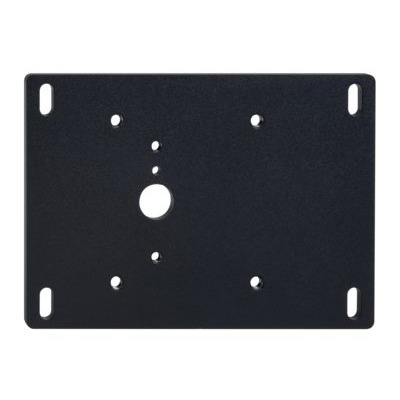
101194224 MP-AZ/AZM201-P1
- 可方便快捷安装的安装底板
- 金属,粉末喷涂
- 适用于左右铰链门
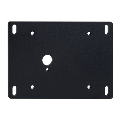
101194218 MP-AZ/AZM201-B30
- 可方便快捷安装的安装底板
- 金属,粉末喷涂
- 适用于左右铰链门
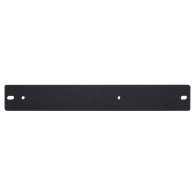
101188600 MP-AZ/AZM201
- 可方便快捷安装的安装底板
- 金属,粉末喷涂
清单
- 1 关于该文件
- 1.1 功能
- 1.2 目标群:拥有授权的专业人员
- 1.3 应用符号
- 1.4 用途
- 1.5 安全信息
- 2 产品描述
- 2.1 订货代码
- 2.2 特殊型号
- 2.3 用途
- 2.4 警告
- 2.5 免责条款
- 2.6 技术参数
- 3 安装
- 3.1 安装概述
- 3.2 尺寸
- 4 电气连接
- 4.1 电气接线指示
- 4.3 串联诊断-SD
- 4.4 串联接线示例
- 4.5 接线配置和连接器配件
- 5 操动件教学 / 操动件监测
- 6 主动原理和诊断功能
- 6.1 磁力控制
- 6.2 安全输出的工作方式
- 6.3 诊断LED
- 6.4 带常规诊断输出的电磁安全锁
- 6.5 带串联诊断功能SD的电磁安全锁
- 7 调试与维护
- 8 拆卸与处理
- 8.1 拆卸
- 8.2 处理
- 9 附录 – 特殊版本
1 关于该文件
1.1 功能
本文件提供了安装、设置和调试所需的所有信息,以确保开关设备的安全操作和拆卸。设备附带的操作说明书必须始终保持清晰易读。
1.2 目标群:拥有授权的专业人员
本操作说明书中描述的所有操作必须由经过培训的专业人员执行,并由工厂操作员授权。
本说明书应清晰可读,并置于设备附近醒目位置。
开关的选择,安装及集成由机器制造商根据相关的法规和要求来考虑。
我司对所有信息不承担责任,且对技术变更权利予以保留。
1.3 应用符号
- 信息,提示,说明: 该符号标示出了有用的附加信息。
- 注意:不注意这些警告提示的话可能导致失败或故障
警告:不注意这些警告提示的话可能导致身体受伤和/或机器损害。
1.4 用途
施迈赛公司的产品系列并不是为大众消费者准备的。
该产品可作为一个整体系统或机器的安全功能的一部分来使用。由系统或机器的生产者来保证系统或机器整体的运作。
该安全产品只可在满足本安装指导书所述条件或得到生产供应商允许的环境中使用。相应的应用领域的信息,请参阅章节:产品描述。
1.5 安全信息
用户必须遵守本说明书以及国家特定的安装标准,以及安全和事故预防规定中的安全指示。
- 更多的技术信息您可以通过施迈赛产品目录或者登陆施迈赛公司网址:products.schmersal.com 在线目录进行查询。
2 产品描述
2.1 订货代码
| 产品描述: AZM201(1)-(2)-(3)-T-(4)-(5) |
| (1) | |
| Z | 电磁安全锁,受监控 |
| B | 操动件,受监控 |
| (2) | |
| 无 | 标准编码 |
| I1 | 独立编码 |
| I2 | 独立编码,多次示教 |
| (3) | |
| SK | 螺丝端子 |
| CC | 笼式接线夹 |
| ST2 | 连接插头M12,8芯 |
| (4) | |
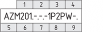
| 1P2PW | 1诊断输出,p型和>2安全输出,p型>(组合诊断信号:防护系统关闭和互锁锁定) |
| SD2P | 串联诊断输出以及2个P型安全输出 |
| (5) | |
| 无 | 通电开锁 |
| A | 通电上锁 |
| 操动件 | 适用于 |
|---|---|
| AZ/AZM201-B1-... | 滑动安全门 |
| AZ/AZM201-B30-... | 铰链安全门 |
| AZ/AZM201-B40-... | 带折叠门扇的铰链门 |
2.2 特殊型号
符合标准规格但在型号描述中未提及的特殊型号,本说明书仍适用。
- 特殊信息或与标准版本不同的信息可在最后一章“附录-特殊版本”中找到。
2.3 用途
非接触式电子安全开关设计用于在安全回路中监控可移动式防护门的位置和锁定。
- 安全开关根据EN ISO 14119分类为4型联锁设备。带有单独编码的设计被分为高度编码。
不同的型号可以作为带有联锁功能或是电磁安全锁的安全开关。
- 如果风险分析表明使用了受监控的联锁,则应使用带受监控联锁的型号,并在订货代码中标记为>符号
操动件监控器(B)是带有对过程保护起联锁功能的安全开关。
本产品的安全功能在于,在防护门解锁或打开的过程中确保关闭安全输出,并在防护门打开的状态下始终确保安全输出保持关闭状态。
- 在特殊情况下,必须首先对事故风险进行彻底评估,方允许使用通电上锁工作原理的联锁设备,因为防护门有可能在电源出现故障或主开关激活时,立即开启。
可串联连接。在串联的情况下,风险时间保持不变,反应时间按技术数据中规定的每增加一个单位的输入的反应时间的总和增加。根据技术数据,设备数量仅受电缆掉落和外部电缆熔断保护的限制。最多可串联31个具有串行诊断功能的设备型号。
- 用户在评估和设计安全链时,必须根据相关标准和和规定,并满足所要求的安全等级。如果同一个安全功能当中包含多个安全开关,必须将单个组件的PFH值相加。
- 集成了安全部件在内的完整控制系统设计必须符合相关标准。
2.4 警告
- 错误使用或操控安全开关可能导致人身伤害,并损坏机器或整个系统。在注意安全指示和注意操作说明书中个关于安装,调试,操作,维护的指示的情况下,其余风险未知。
2.5 免责条款
我司不承担由于错误安装或未按照本说明书安装而造成的损失。我司不承担由于未使用我司认可的组件或配件而造成的损失。
出于安全原因,严禁对设备进行介入性工作,禁止擅自修理、改造、改装设备。我司不承担由于介入性工作、擅自修理、改造及改装而造成的损失。
2.6 技术参数
许可 - 标准
| 证书 |
TÜV cULus FCC IC UKCA ANATEL |
总体数据
| 标准型 |
EN ISO 13849-1 EN ISO 14119 EN IEC 60947-5-3 EN IEC 61508 |
| 编码 |
单独编码,多次示教 |
| 编码等级,依据EN ISO 14119 |
高 |
| 工作原理 |
RFID |
| 频段 RFID |
125 kHz |
| 发射器输出 RFID, 最大植 |
-6 dBm |
| 外壳材料 |
玻璃纤维,加强型热塑塑料 |
| 风险持续期,最大 |
200 ms |
| 响应时间, 通过执行机构关闭安全输出,最大 |
100 ms |
| 响应时间,通过安全输入关闭安全输出,最大值 |
1.5 ms |
| 毛重 |
595 g |
总体数据 - 产品特性
| 通电解锁 |
是 |
| 电磁安全锁,受监控 |
是 |
| 串联诊断 |
是 |
| 手动解锁 |
是 |
| 短路检测 |
是 |
| 交叉电路检测 |
是 |
| 串联连接 |
是 |
| 安全功能 |
是 |
| 整个系统检测,状态 |
是 |
| 安全触点数量 |
2 |
| 传感器串联数量 |
31 |
安全评估
| 标准型 |
EN ISO 13849-1 EN IEC 61508 |
安全评估 - 联锁
| 性能水平,最高 |
e |
| 类别 |
4 |
| PFH值 |
1.90 x 10⁻⁹ /h |
| PFD值 |
1.60 x 10⁻⁴ |
| 安全完整性等级 (SIL),停止 0,适用于以下应用 |
3 |
| 任务时间 |
20 年 |
机械参数
| 机械寿命,最少 |
1,000,000 操作 |
| 保持力 FZh 按照 EN ISO 14119 |
2,000 N |
| 注意 (合型力 FZh) |
1,000 N 当使用↲AZ/ AZ/AZM201-B30操动件,用于室内. |
| 锁紧力 Fmax, 最大 |
2,600 N |
| 注意 (合型力 Fmax) |
1,300 N 当使用↲AZ/ AZ/AZM201-B30操动件,用于室内. |
| 锁定力 |
30 N |
| 操动速度,最大 |
0.2 m/s |
| 固定螺丝类型 |
2x M6 |
| 固定螺钉的紧锢力矩, 最大值 |
8 Nm |
| 箱盖紧固螺钉的拧紧扭矩,最低 |
0.7 Nm |
| 箱盖紧固螺钉的拧紧扭矩,最大 |
1 Nm |
| 注意 |
Torx T10 |
机械参数 - 连接技术
| 传感器链长度,最大 |
200 m |
| 注意 (传感器链长度) |
根据输出电流,电缆长度和电缆截面会改变电压降 |
| 注意 (串联连接) |
设备数量不限,oberserve 外部线路熔断,最多可连接 31 台设备。在串行诊断 SD 的情况下,最多可连接 31 台设备 |
| 连接器 |
连接器M12,8芯 |
机械参数 - 尺寸
| 传感器长度 |
50 mm |
| 传感器宽度 |
40 mm |
| 传感器高度 |
220 mm |
环境条件
| 防护等级 |
IP66 IP67 |
| 工作环境温度 |
-25 ... +60 °C |
| 储存和运输温度 |
-25 ... +85 °C |
| 最大相对湿度 |
93 % |
| 注(相对湿度) |
无冷凝 不结冰 |
| 抗振动 |
10 ... 150 Hz,振幅 .35 mm |
| 耐冲击 |
30 g / 11 ms |
| 防护等级 |
III |
| 最大允许安装海拔高度 |
2,000 m |
环境条件 - 绝缘值
| 额定绝缘电压 Ui |
32 VDC |
| 额定冲击耐受电压 Uimp |
0.8 kV |
| 过电压级别 |
III |
| 污染等级 |
3 |
电气参数
| 工作电压 |
24 VDC -15 % / +10 % (稳定PELV电源) |
| 空载电源电流 I0, 典型 |
50 mA |
| 磁铁接通时的电流消耗,平均值 |
200 mA |
| 磁铁接通时的电流消耗, 峰值 |
700 mA / 100 ms |
| 额定工作电压 |
24 VDC |
| 工作电流 |
1,200 mA |
| 要求额定短路电流 |
100 A |
| 外部电线和设备保险丝额定值 |
2 A gG |
| 准备就绪时间,最大 |
4,000 ms |
| 转换频率,最大 |
1 Hz |
电气参数 - 线圈控制
| 指定, 线圈控制 |
IN |
| 开关阈值 |
-3 V … 5 V (Low) 15 V … 30 V (High) |
| 磁铁闭合时间 |
100 % |
| 测试脉冲持续时间, 最大 |
5 ms |
| 测试脉冲间隔, 最低限度 |
40 ms |
| 分类 ZVEI CB24I,接收器 |
C0 |
| 分类 ZVEI CB24I,信号源 |
C1 C2 C3 |
电子参数 - 安全数字输入
| 指定,安全输入 |
X1 和 X2 |
| 开关阈值 |
−3 V … 5 V (Low) 15 V … 30 V (High) |
| 24V时,电流消耗 |
5 mA |
| 测试脉冲持续时间, 最大 |
1 ms |
| 测试脉冲间隔, 最低限度 |
100 ms |
| 分类 ZVEI CB24I,接收器 |
C1 |
| 分类 ZVEI CB24I,信号源 |
C1 C2 C3 |
电气参数 - 安全数字输出
| 指定,安全输出 |
Y1和Y2 |
| 额定工作电流(安全输出) |
250 mA |
| 控制元件的设计 |
短路保护,P型 |
| 电压降 Ud, 最大电压降 Ud, 最大 |
2 V |
| 泄漏电流 Ir, 最大植 |
0.5 mA |
| 电压,应用类别 DC-13 |
24 VDC |
| 电流,应用类别 DC-13 |
0.25 A |
| 测试脉冲间隔,典型 |
1000 ms |
| 测试脉冲持续时间, 最大 |
0.5 ms |
| 分类 ZVEI CB24I,信号源 |
C2 |
| 分类 ZVEI CB24I,接收器 |
C1 C2 |
电子参数 - 串行诊断SD
| 指定,串联诊断SD |
OUT |
| 工作电流 |
150 mA |
| 控制元件的设计 |
短路保护,P型 |
| 布线电容 |
50 nF |
状态显示
| 注 (LED开关状态显示) |
工作状态:LED绿色 错误 / 功能故障:LED红色 供电电压 UB:LED 绿色 |
引脚分配
| PIN 1 |
A1 电源电压 UB |
| PIN 2 |
X1 安全输入 1 |
| PIN 3 |
A2 GND |
| PIN 4 |
Y1 安全输出 1 |
| PIN 5 |
OUT 串行诊断输出 |
| PIN 6 |
X2 安全输入 2 |
| PIN 7 |
Y2 安全输出 2 |
| PIN 8 |
IN 串行诊断输入 |
安全分类注意事项
- 防护锁定功能的安全分类仅适用于带受监控电磁安全锁AZM201Z...1P2PW-… 的标准设备(见订货代码)。因为SD网关的不安全锁定/解锁信号,不允许对串联诊断“SD2P”装置的防护锁定功能进行安全分类。
- 如果操作安全分析表明,不能使用静态电流版本的电磁安全锁,则可作为一个例外情况,使用通电上锁的锁,前提是必须采取附加安全措施,确保相应的安全水平。
- 防护锁定功能的安全分析是指将电磁安全锁AZM作为整个系统的一部分。
客户方必须执行进一步措施以避免发生故障,例如安全操动和安全地连接电缆。
如果出现某一故障导致锁定功能解锁,电磁安全锁将会探测到这一情况,防护门Y1/Y2将会安全关闭。当这种故障发生时,在机器达到安全状态之前,保护设备可能会立即打开,仅有一次。类别2所定义的系统反应允许在检测之间发生故障,并导致安全功能丧失,而安全功能丧失的情况则由检测功能探测识别出来。
- 联锁的操动必须与OSSD释放器进行外部比较。如果是由于非故意解锁而导致的停机,则会通过外部诊断检测到。
UL 注意
仅限使用绝缘供电。仅限用于NFPA 79应用。制造商提供现场接线方式的适配器。参见制造商信息。
FCC/IC - 注意
本设备符合FCC规则第15部分,并包含符合ISED(创新、科学和经济发展)加拿大免许可RSS标准的免许可发射器/接收器。
操作须满足以下两个条件:
(1) 该设备不得产生有害的干扰信号;
(2) 该设备必须能够承受干扰信号。其中还包括可能导致设备无法正常工作的干扰信号。
该设备在最小距离为100 mm时符合神经刺激限制 (ISED SPR-002)。未经K.A. Schmersal GmbH & Co. KG明确批准的更改或修改 可能会导致用户使用该设备的授权失效。
该设备中包含的免许可发射器/接收器满足加拿大创新、科学和经济发展(ISED)机构适用于免许可无线电设备的“无线电标准规范”的要求。在下列两种情况下允许操作:
(1) 该设备不得产生干扰。
(2) 设备必须能够承受接收到的射频干扰,即使这可能会损害其功能。
该设备在最小距离为 100 mm时符合神经刺激限制 (ISED CNR-102)。
如果未经K.A.Schmersal GmbH & Co. KG明确批准进行的更改或修改 可能会导致用户使用该设备的授权失效。
| 20941-22-14519 | Este equipamento nao tem direito àprotecao contra interferência prejudicial e nao pode causar interferencia em sistemas devidamente autorizados. Para maiores informacores consultar: www.gov.br/anatel |
3 安装
3.1 安装概述
- 请遵守标准ISO 12100, ISO 14119和 ISO 14120。
为固定安全开关和操动件,各提供两个固定螺孔及适合的M6螺栓和垫圈(包含在配货中)。安全开关本身不可作为机械限位使用。任何位置都是可能的。但是选择的安装位置必须是防止污垢侵入的开口。未使用的操动件开口必须使用防尘盖密封(配货范围内包含)。
两个安全开关设备之间以及与频率相同(125 kHz)
的其他系统之间的最小距离:100 mm。

操动件安装
参见相应操动件的操作说明书。
- 操动件必须永久固定在安全防护门上,通过合适的措施防止移位(防破坏螺栓、胶接、螺栓头钻孔等)。
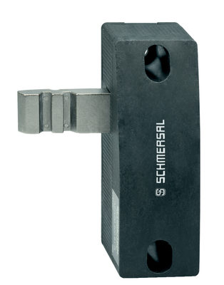
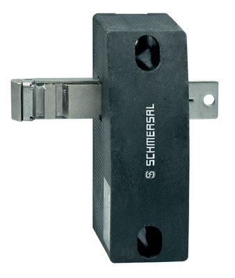
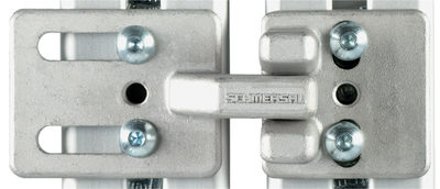
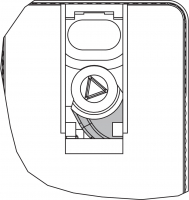
手动解锁
装设备时,可在断电情况下对电磁安全锁解锁。打开塑料挡板“A”之后(见下图“尺寸”),可顺时针转动三角钥匙将电磁安全锁改为解锁状态。只有在将三角钥匙转回初始位置后方可恢复正常的锁定功能。
- 注意:切勿超过卡定位置过度旋转,最大拧紧扭矩:1.3 Nm。
成功完成启动调试之后,使用塑料挡板“A”关闭手动解锁功能,并使用随附的封签封死。
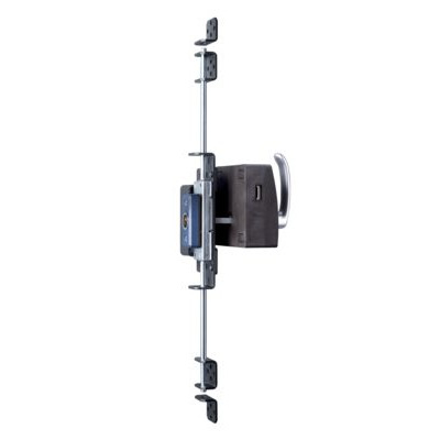
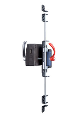
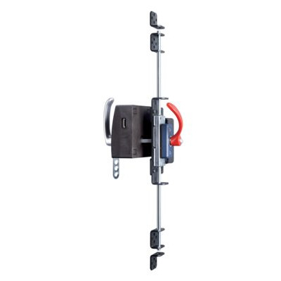
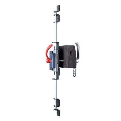
| 正常功能状态 | 非正常功能状态 |
 | 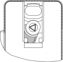 |
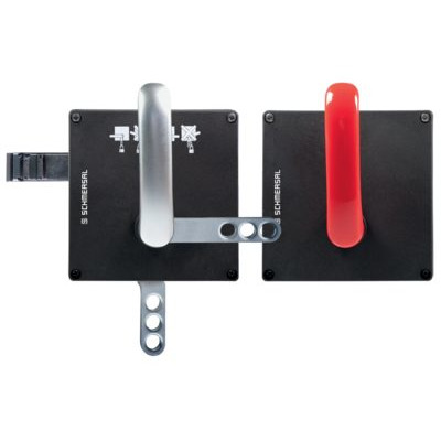
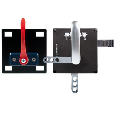
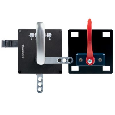
3.2 尺寸
测量值均以mm为单位。
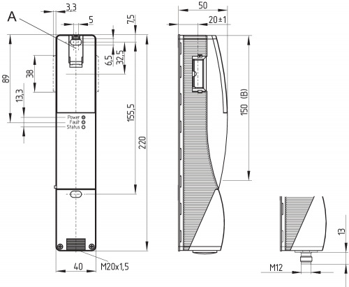
图例
A: 手动解锁
B: RFID区域
- 安全开关装置和操动件的横向RFID区域中的金属件及磁场会影响开关距离或导致故障。
改装套件用于随后对电磁安全锁进行功能扩展。
| 名称 | 订货代码 | |
|---|---|---|
| 紧急解锁 | RF-AZM200-N | 103003543 |
| 紧急逃逸 | RF-AZM200-T | 103004966 |
4 电气连接
4.1 电气接线指示
- 电气接线需在电源关闭的情况下由授权专业人员完成。
电源必须具有永久性过压保护。推荐使用符合标准EN 60204-1的电源。
所需的电缆保险丝保护必须集成在安装中。
安全输出可直接接入控制系统的安全电路。
连接安全监控模块的要求
双通道安全输入,适于2个 p-型半导体输出
- 安全控制器配置
如果安全开关设备连接到电子安全监控模块,我们建议您设置至少100 ms的差异时间。安全监控模块的安全输入必须能够消隐大约1 ms的测试脉冲。安全监控模块不需要具有交叉短路监控功能,如有必要,必须关闭交叉短路监控。
- 有关选择合适安全监控模块的技术信息,请查阅施迈赛产品目录或访问以下网址,查阅在线目录:products.schmersal.com
电缆进口采用公制M20电缆压盖。格兰头规格由用户根据使用的电缆规格搭配。必须使用具有应力消除装置和适当IP防护等级的电缆压盖。
导体的固定长度x:
- 螺丝端子(SK): 8 mm
- 笼式接线夹(CC)s,r或f型: 7.5 mm

4.3 串联诊断-SD
- 已安装的24V,X1,X2桥接包含在…-1P2PW和…-SD2P的配货范围内。
- 连接SD设备时,请注意电缆电压降以及各个组件的电流负载能力。
- 串联连接配件
为了方便接线和SD组件的串联连接,可选用SD接线盒 PFB-SD-4M12-SD(用于现场安装)和PDM-SD-4CC-SD(用于控制柜内导轨安装),还可利用其它综合配件。详细信息见products.schmersal.com
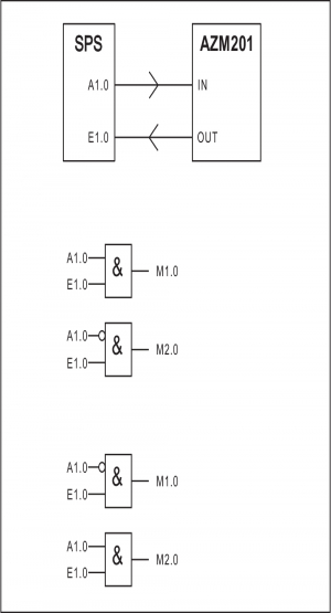
4.4 串联接线示例
串联连接为可行选择。在串联的情况下,风险时间保持不变,反应时间按技术数据中规定的每增加一个单位的输入的反应时间的总和增加。根据技术数据,设备数量仅受电缆掉落和外部电缆熔断保护的限制。最多可接入31台带串联监控功能的AZM201...SD设备。
图中所示应用仅为示例。并不能解除用户事先仔细审查开关及其设置是否符合具体应用要求的责任。图中所示应用仅为示例。
接线示例 1:带常规诊断输出的AZM201串联接线。
在串联情况下,必须移除最后一个组件以外的其它所有组件上的24V-X1-X2桥接。在安全组件链最后一个设备的两个安全输入上接通电压(从安全监控模块查看)。第一个安全组件的安全输出与安全监控模块相连。
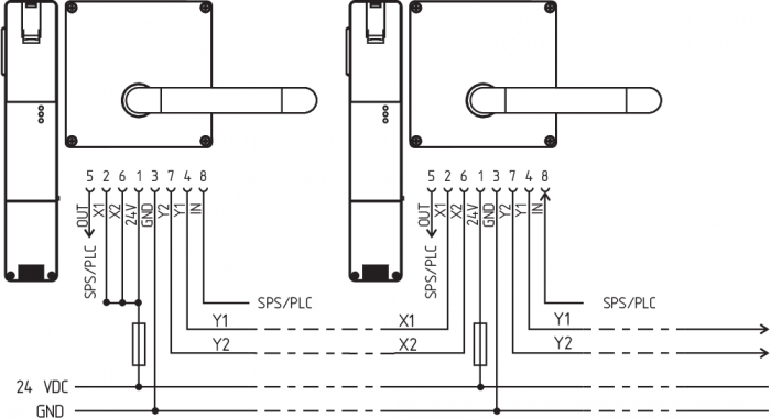
Y1和Y2 = 安全输出 → 安全监控模块
接线示例 2:具有串行诊断功能的AZM201的串联接线(最多串联31个组件)
对于带有串联监控功能的设备(订货后缀-SD),串联监控接口将采用串联方式与用于评估的SD网关相连。第一个安全组件的安全输出与安全监控模块相连。串联监控网关与第一个安全组件的串联诊断输入相连。

Y1和Y2 = 安全输出 → 安全监控模块
SD输入 → 网关 → 现场总线
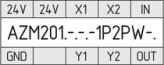
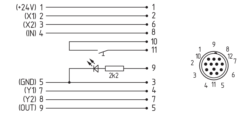
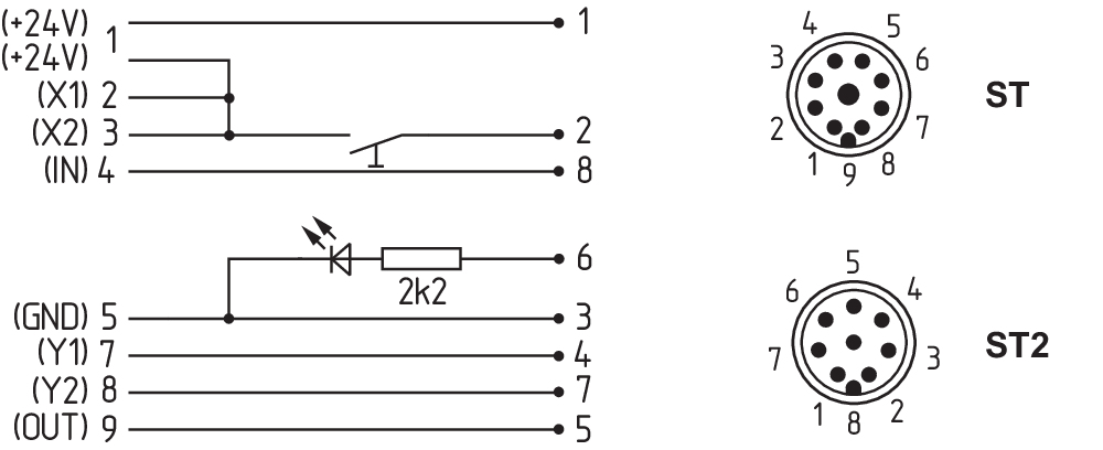
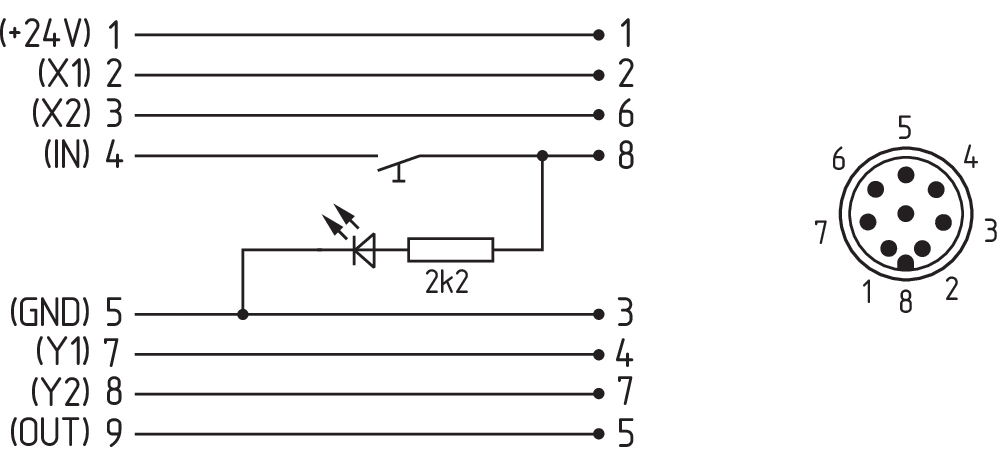
4.5 接线配置和连接器配件
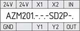
| 安全开关功能 | 连接器 ST2、M12,8针的引脚配置 | 可拆卸端子排配置 | 符合DIN 47100标准的施迈赛连接器插头的颜色代码 | 符合EN 60947-5-2的商用连接插头的其他可能的颜色代码 | ||
|---|---|---|---|---|---|---|
| 带常规诊断输出 | 带串联诊断功能 |  | ||||
| 24V | Ue | 1 | 1 | WH | BN | |
| X1 | 安全输入1 | 2 | 2 | BN | WH | |
| GND | GND | 3 | 5 | GN | BU | |
| Y1 | 安全输出1 | 4 | 7 | YE | BK | |
| OUT | 诊断输出 | SD输出 | 5 | 9 | GY | GY |
| X2 | 安全输入2 | 6 | 3 | PK | PK | |
| Y2 | 安全输出2 | 7 | 8 | BU | VT | |
| IN | 磁力控制 | SD输入 | 8 | 4 | RD | OR |
| 无功能 | - | 6 | ||||
使用Y型分配器CSS-Y-8P Y与SD网关连接时,针脚的不同分配.
| 信号 | 线脚 | 连接器 (2) | 电缆颜色 | |||
|---|---|---|---|---|---|---|
| 施迈赛- 电缆 | 电缆符合 EN 60947-5-2标准 | 电缆符合 DIN 47100标准 | ||||
| A1 | 1 | Ue | BN | BN | WH |  |
| A1 | 2 | Ue | WH | WH | BN | |
| A2 | 3 | GND | BU | BU | GN | |
| A2 | 4 | GND | BK | BK | YE | |
| Y1 | 5 | 安全输出1 | GY | GY | GY | |
| Y2 | 6 | 安全输出2 | VT | 粉色 | PK | |
| IN | 7 | SD输入 | RD | VT | BU | |
| OUT | 8 | SD输出 | PK | OR | RD | |
| 视图订购后缀为 -SK 或 -CC 的端子块 | 视图带可拆卸端子块的版本 | |
|---|---|---|
 |  |  |
| 耦合式连接电缆(母)IP67 / IP69,M12,8针 - 8 x 0.25 mm²,符合DIN 47100 | |
|---|---|
| 电缆长度 | 订货代码 |
| 2.5 m | 103011415 |
| 5.0 m | 103007358 |
| 10.0 m | 103007359 |
| 15.0 m | 103011414 |
5 操动件教学 / 操动件监测
采用标准编码的电磁安全锁到货即可使用。
单独编码的电磁安全锁以及操动件需要进行以下示教步骤:
- 关闭电磁锁的电源并重新接通.
- 将操动件置于探测范围内。电磁安全锁将显示示教正在进行中,红色LED亮起,黄色LED闪烁(1 Hz)。
- 10秒过后,快速闪动黄色信号(3 Hz)提示断开电磁锁的有效电压。(如果电压在5分钟内未断开,电磁安全锁将中断示教步骤并闪烁5次红灯,表示操动件错误)。
- 一旦工作电压重新接通,必须再次检测操动件,以激活已示教的操动件代码。这一操作将确定保存已激活的编码!
对于订购后缀为-I1的设备,安全开关设备和操动件的执行分配是不可逆的。
对于订货后缀为-I2的设备,可无限次地重新示教新的操动件。示教新操动件时,此前的编码将作废。随后,将启动一个为时10分钟的放行阻止程序,此间防止更改的保护性能将提高。放行阻止程序结束时,绿色LED将会闪烁亮起,表明探测到了新操动件。如果在10分钟的放行阻止期间发生断电,则该程序会重新启动。
6 主动原理和诊断功能
6.1 磁力控制
对于采用通电开锁方式的AZM201,电磁安全锁在收到输入信号IN(= 24 V)时即会解锁。而对于通电上锁版本的AZM201,电磁安全锁在收到输入信号 IN(= 24 V)时即会锁定。
6.2 安全输出的工作方式
对于标准规格的的AZM201,电磁安全锁解锁会导致安全输出断开。操动件保持插入在AZM201电磁安全锁当中,已解锁的防护门会重新锁定。在这种情况下,安全输出会重新接通。
无需打开安全门。
对于B型变体AZM201B,开启防护门会导致安全输出断开。
6.3 诊断LED
电磁安全锁通过位于前面板上的三个彩色LED指示灯显示其工作状态及错误。
| 绿色(电源) | 供电电压接通 |
| 黄色(状态) | 工作状态 |
| 红色(故障) | 错误(见表 2: 错误信息 / 红色诊断LED的指示灯编码 |
6.4 带常规诊断输出的电磁安全锁
抗短路诊断输出OUT可用于中央显示,或者用于非安全控制功能当中,例如PLC。
诊断输出是非安全相关的输出。
错误
不再保证安全开关设备功能的错误(内部错误)会导致安全输出在风险持续时间内被禁用。故障排除后,可通过开启并重新锁定相应的防护门复位故障消息。
- 如果在安全输出中检测到不止一个故障或在Y1和Y2之间检测到交叉电路,则自动进行电子锁定。这意味着,常规的错误将无法确认。要复位此类联锁,必须在消除错误原因后将电磁安全锁与电源电压切断。
故障警告
不会立即危及安全开关设备安全功能的故障(例如环境温度过高、外部电位安全输出、交叉电路)会导致延迟关闭(见表 2)。使用诊断输出断开但安全通道仍闭合这一信号组合可将机器在受控状态下停止。当错误原因排除后,错误警告则被删除。如果故障警告持续30分钟,安全输出也会关闭(红色LED闪烁,请参见表 2)。
诊断输出的行为(版本…- 1P2PW)
(例如:通电开锁类型)
磁力控制的输入信号

常规流程,门被锁止
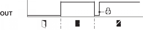
门无法锁止或故障

 | 锁定 |  | 解锁 | ||
 | 防护门打开 |  | 防护门关闭 |  | 上锁时间:150 ... 250 ms, 通常 200 ms |
 | 防护门未锁止或故障 |  | 防护门锁止 |
诊断输出的评估(版本…- 1P2PW)
| 表 1:安全开关的诊断信息 | ||||||||
|---|---|---|---|---|---|---|---|---|
| 系统环境 | 磁力控制 IN | LED | 安全输出 Y1, Y2 | 诊断输出OUT | ||||
| 通电解锁 | 通电上锁 | 绿色 | 红色 | 黄色 | AZM201Z | AZM201B | -1P2PW | |
| 防护门打开 | 24 V (0 V) | 0 V (24 V) | 开 | 关 | 关 | 0 V | 0 V | 0 V |
| 防护门关闭,操动件未插入 | 24 V | 0 V | 开 | 关 | 关 | 0 V | 0 V | 0 V |
| 防护门关闭,操动件插入,未锁止 | 24 V | 0 V | 开 | 关 | 闪烁 | 0 V | 24 V | 24 V |
| 防护门关闭,操动件插入, 联锁被阻止 | 0 V | 24 V | 开 | 关 | 闪烁 | 0 V | 24 V | 0 V |
| 门关闭,操动件插入并锁定 | 0 V | 24 V | 开 | 关 | 开 | 24 V | 24 V | 24 V |
| 错误警告1) 电磁安全锁锁定 | 0 V | 24 V | 开 | 闪烁 2) | 开 | 24 V1) | 24 V1) | 0 V |
| 错误 | 0 V (24 V) | 24 V (0 V) | 开 | 闪烁2)/关闭1) | 关 | 0 V | 0 V | 0 V |
| 额外对于I1和I2型: | ||||||||
| 示教过程操动件启动 | 关 | 开 | 闪烁 | 0 V | 0 V | 0 V | ||
| 仅I2:示教过程操动件 (释放块) | 闪烁 | 关 | 关 | 0 V | 0 V | 0 V | ||
1) 30分钟后:由于故障停用 2) 参考闪烁编码 | ||||||||
| 表2:错误信息/红色诊断LED的闪烁编码 | |||
|---|---|---|---|
| 指示灯编码 | 名称 | 自行关闭等候时间 | 错误原因 |
| 1次闪烁 | 错误(警告)位于输出Y1 | 30分钟 | 输出测试错误或输出Y1断开后仍存在电压。 |
| 2次闪烁 | 错误(警告)位于输出Y2 | 30分钟 | 输出测试错误或输出Y2断开后仍存在电压。 |
| 3次闪烁 | 错误(警告)交叉短路 | 30分钟 | 输出电缆交叉短路或两个输出端口故障 |
| 4次闪烁 | 错误(警告)温度过高 | 30分钟 | 温度测量显示内部温度过高 |
| 5次闪烁 | 操动件故障 | 0分钟 | 操动件错误或故障 |
| 6次闪烁 | 操动件组合错误 | 0分钟 | 探测到操动件的无效组合(发现锁舌断裂或蓄意破坏)。 |
| 持续亮起红色信号 | 内部故障 / 过电压或欠电压故障 | 0分钟 | 设备故障 / 供电电压不在规格范围内 |
6.5 带串联诊断功能SD的电磁安全锁
带串联诊断电缆的电磁安全锁包含一个串联输入和串联输出电缆,而非常规的诊断输出。如果串联电磁安全锁,诊断数据则通过串联的输入和输出进行传输。
最多可串联31台电磁安全锁。对于串行诊断线路的评估,可以使用 PROFIBUS-Gateway SD-I-DP-V0-2 或 Universal-Gateway SD-I-U-...。该串联监控接口将作为附属装置连入一个已有的现场总线系统。因此,诊断信号可通过PLC评估。
请访问products.schmersal.com下载SD网关接入所需的技术文档。
响应和诊断数据会自动不断写入串联链中每个电磁安全锁的PLC的一个输入字节中。每个电磁安全锁的请求数据会通过PLC的输出字节传送到设备上。SD网关和线圈锁定之间一旦出现通讯错误,线圈锁定将保持现有的开关状态不变。
错误
不再保证安全开关设备功能的错误(内部错误)会导致安全输出在风险持续时间内被禁用。当错误原因消除且请求字节的位7从1变为0,或者防护门打开后,错误则被重置。只有在下一次放行时安全输出的错误才会被删除,因为之前无法探测到故障已排除。
- 如果在安全输出中检测到不止一个故障或在Y1和Y2之间检测到交叉电路,则自动进行电子锁定。这意味着,常规的错误将无法确认。要复位此类联锁,必须在消除错误原因后将电磁安全锁与电源电压切断。
错误警告
不会立即危及安全开关设备安全功能的故障(例如环境温度过高、外部电位安全输出、交叉电路)会导致延迟关闭。使用诊断输出断开但安全通道仍闭合这一信号组合可将机器在受控状态下停止。
当错误原因消除后,错误警告就会被删除。
如果故障警告持续30分钟,安全输出也会关闭(红色LED闪烁)。
诊断错误(警告)
当响应字节发出错误(警告)信号,可以读取详细错误信息。
| 表3:I/O数据和诊断数据 (当位Bit = 1时,描述状态实现) | ||||
|---|---|---|---|---|
| 位号 | 请求字节 | 响应字节 | 诊断错误警告 | 诊断错误 |
| 位0: | 电磁接通,不受通电上锁或通电解锁的工作原理限制 | 安全输出已激活 | Y1输出错误 | Y1输出错误 |
| 位1: | --- | 探测到操动件 | Y2输出错误 | Y2输出错误 |
| 位2: | --- | 探测到操动件并已锁止 | 交叉短路 | 交叉短路 |
| 位3: | --- | --- | 温度过高 | 温度过高 |
| 位4: | --- | 输入状态X1和X2 | --- | 操动件错误或故障 |
| 位5: | --- | 探测到防护门 | 内部设备错误 | 内部设备错误 |
| 位6: | --- | 错误警告 1) | 现场总线网关与安全开关之间发生通讯错误 | --- |
| 位7: | 错误重置 | 错误 (使能路径断开) | 工作电压过低 | --- |
| 1) 30分钟后 -> 故障 | ||||
7 调试与维护
该安全开关的安全功能必须进行检查。在正确安装和恰当使用的前提下,本安全开关的功能性无需保养。推荐按照下列内容进行常规的目测检查和功能测试:
- 检查安全开关和操动件的安装是否稳固。
- 检查操动件和安全开关之间的最大轴向调节。
- 安装并确保电缆连接完好无损。
- 检查开关外壳是否损坏
- 去除污垢。
- 必须采取相应措施以防止发生蓄意破坏或回避安全防护装置的行为,例如可使用替代操动件。
- 损坏或故障部件必须更换。
8 拆卸与处理
8.1 拆卸
该开关必须在电源关闭的情况下进行拆卸。
8.2 处理
- 该开关必须按照相关的国家标准和法规进行处理。
9 附录 – 特殊版本
特殊型号 -2965-1
| 连接电缆 带耦合器(母)IP67,M23,12针 - 12 × .75 mm² | |
|---|---|
| 电缆长度 | 订货代码 |
| 5.0 m | 101208520 |
| 10.0 m | 103007354 |
| 20.0 m | 101214418 |
特殊型号 -2965-2
| 连接电缆 带耦合器(母)IP67,M23,8+1针 - 9 × 0.75 mm² | |
|---|---|
| 电缆长度 | 订货代码 |
| 5.0 m | 101209959 |
| 10.0 m | 101209958 |
| 15.0 m | 103001384 |
| 连接电缆 带耦合器(母)IP67,M12,8针 - 8 × 0.25 mm² | |
|---|---|
| 电缆长度 | 订货代码 |
| 2.5 m | 103011415 |
| 5.0 m | 103007358 |
| 10.0 m | 103007359 |
特殊型号 -2965-3
| 连接电缆 带耦合器(母)IP67,M12,8针 - 8 × 0.25 mm² | |
|---|---|
| 电缆长度 | 订货代码 |
| 2.5 m | 103011415 |
| 5.0 m | 103007358 |
| 10.0 m | 103007359 |
| EU Declaration of Conformity |  |
| Original | K.A. Schmersal GmbH & Co. KG Möddinghofe 30 42279 Wuppertal Germany Internet: www.schmersal.com |
| Declaration: | We hereby certify that the hereafter described components both in their basic design and construction conform to the applicable European Directives. |
| Name of the component: | AZM201 |
| Type: | See ordering code |
| Description of the component: | Interlocking device with electromagnetic interlock for safety functions |
| Relevant Directives: | Machinery Directive | 2006/42/EC |
| RED-Directive | 2014/53/EU | |
| RoHS-Directive | 2011/65/EU |
| Applied standards: | EN 60947-5-3:2013 ISO 14119:2013 EN 300 330 V2.1.1:2017 EN ISO 13849-1:2015 EN 61508 parts 1-7:2010 |
| Notified body for Type Examination: | TÜV Rheinland Industrie Service GmbH Am Grauen Stein, 51105 Köln ID n°: 0035 |
| Type Examination Certificate: | 01/205/5608.01/22 |
| Person authorised for the compilation of the technical documentation: | Oliver Wacker Möddinghofe 30 42279 Wuppertal |
| Place and date of issue: | Wuppertal, August 10, 2022 |
 |
| Authorised signature Philip Schmersal Managing Director |
| UK Declaration of Conformity | |
| Company: | K.A. Schmersal GmbH & Co. KG Möddinghofe 30 42279 Wuppertal Germany Internet: www.schmersal.com |
| Declaration: | We hereby, under sole responsibility, certify that the hereafter described components both in their basic design and construction conform to the relevant statutory requirements, regulations and designated standards of the United Kingdom. |
| Name of the component: | AZM201 |
| Type: | See ordering code |
| Description of the component: | Interlocking device with electromagnetic interlock for safety functions |
| Relevant legislation: | Supply of Machinery (Safety) Regulations | 2008 |
| Radio Equipment Regulations | 2017 | |
| The Restriction of the Use of Certain Hazardous Substances in Electrical and Electronic Equipment Regulations | 2012 |
| Designated standards: | EN 60947-5-3:2013 ISO 14119:2013 EN 300 330 V2.1.1:2017 EN ISO 13849-1:2015 EN 61508 parts 1-7:2010 |
| Approved body for Type Examination: | TÜV Rheinland UK Ltd. 1011 Stratford Road Solihull, B90 4BN ID: 2571 |
| Type examination certificate: | 01/205U/5608.00/22 |
| UK-Importer / Person authorised for the compilation of the technical documentation: | Schmersal UK Ltd. Paul Kenney Unit 1, Sparrowhawk Close Enigma Business Park Malvern, Worcestershire, WR14 1GL |
| Place and date of issue: | Wuppertal, September 28, 2022 |
|
| Authorised signature Philip Schmersal Managing Director |
施迈赛工业开关制造(上海)有限公司, 上海市青浦区漕盈路3336号,
所涉及的详细信息和数据已经过仔细检查。 图像可能与原始图像有所不同。 您可在说明书中进一步获得技术数据。 可能会有技术修改和错误。
生成日期 2025/9/21 下午6:28