CSS 14-34-S-SD-M-L
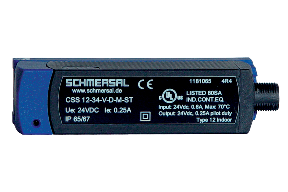
CSS 14-34-S-SD-M-L
| Product type description: CSS (1)-34-(2)-(3)-(4)-M-(5) |
| (1) | |
| 12 | Actuation from top |
| 14 | Actuation from side |
| (2) | |
| without | Standard version |
| F0 | Input for enabling pushbutton, suitable for automatic start |
| F1 | Input for reset pushbutton, with edge monitoring |
| (3) | |
| S | lateral active surface |
| V | frontal active surface |
| (4) | |
| D | With diagnostic output |
| SD | Serial diagnostic output |
| (5) | |
| L | with connecting cable |
| ST | with connector |
- 1 x Pre-wired cable 8-pole
- Actuation from side
- serial diagnostic output
- Max. 31 sensors can be wired in series.
- Thermoplastic enclosure
- Electronic contact-free, coded system
- Misaligned actuation possible
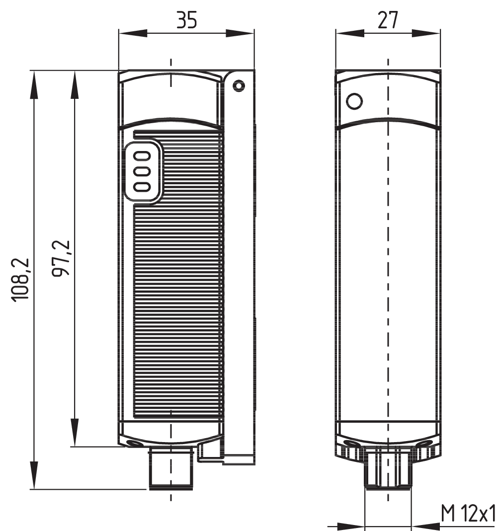
- 27 mm x 108.2 mm x 35 mm
- High repeat accuracy of the switching points
- Max. length of the sensor chain 200 m
- 2 short-circuit proof PNP safety outputs
- Integral cross-short, wire-breakage and external voltage monitoring of the safety cables up to the control cabinet
Ordering data
| Product type description |
CSS 14-34-S-SD-M-L |
| Article number (order number) |
101181061 |
| EAN (European Article Number) |
4030661314853 |
| eCl@ss number, version 12.0 |
27-27-46-01 |
| eCl@ss number, version 11.0 |
27-27-24-03 |
| eCl@ss number, version 9.0 |
27-27-24-03 |
| ETIM number, version 7.0 |
EC001829 |
| ETIM number, version 6.0 |
EC001829 |
Approvals - Standards
| Certificates |
TÜV cULus UKCA |
General data
| Standards |
EN IEC 60947-5-3 |
| Working principle |
inductive |
| Housing construction form |
Block |
| Installation conditions (mechanical) |
not flush |
| Sensor topology |
Sensor for series wiring |
| Housing material |
Glass-fibre, reinforced thermoplastic |
| Active area |
Glass-fibre, reinforced thermoplastic |
| Reaction time, maximum |
30 ms |
| Duration of risk, maximum |
60 ms |
| Gross weight |
295 g |
General data - Features
| Serial diagnostics |
Yes |
| Diagnostic output |
Yes |
| Short circuit detection |
Yes |
| Cross-circuit detection |
Yes |
| Safety functions |
Yes |
| Cascadable |
Yes |
| Integral system diagnostics, status |
Yes |
| Number of LEDs |
3 |
| Number of semi-conductor outputs with signaling function |
1 |
| Number of fail-safe digital outputs |
2 |
| Number of series-wiring of sensors |
31 |
| Safety classification |
| Standards |
EN ISO 13849-1 EN IEC 60947-5-3 EN IEC 61508 |
| Performance Level, up to |
e |
| Category |
4 |
| PFH value |
3.60 x 10⁻⁹ /h |
| Safety Integrity Level (SIL), suitable for applications in |
3 |
| Mission time |
20 Year(s) |
Mechanical data
| Actuating panels |
lateral |
| Active area |
lateral |
| Switching distance actuator |
Actuator CST 34-V-1: 10 mm (typical switch distance Sn) Actuator CST 34-V-1: 8 mm (ensured switch distance ON Sao) Actuator CST 34-V-1: 13 mm (ensured switch distance OFF Sar) Actuator CST 34-S-1 / CST 34-S-3: 14 mm (typical switch distance Sn) Actuator CST 34-S-1 / CST 34-S-3: 12 mm (ensured switch distance ON Sao) Actuator CST 34-S-1 / CST 34-S-3:: 17 mm (ensured switch distance OFF Sar) Actuator CST 34-S-2: 14 mm (typical switch distance Sn) Actuator CST 34-S-2: 12 mm (ensured switch distance ON Sao) Actuator CST 34-S-2: 17 mm (ensured switch distance OFF Sar) Actuator CST 180-1 / CST 180-2: 10 mm (typical switch distance Sn) Actuator CST 180-1 / CST 180-2: 8 mm (ensured switch distance ON Sao) Actuator CST 180-1 / CST 180-2: 13 mm (ensured switch distance OFF Sar) |
Mechanical data - Switching distances according EN IEC 60947-5-3
| Hysteresis (Switching distance), maximum |
1.5 mm |
| Repeat accuracy R |
0.5 mm |
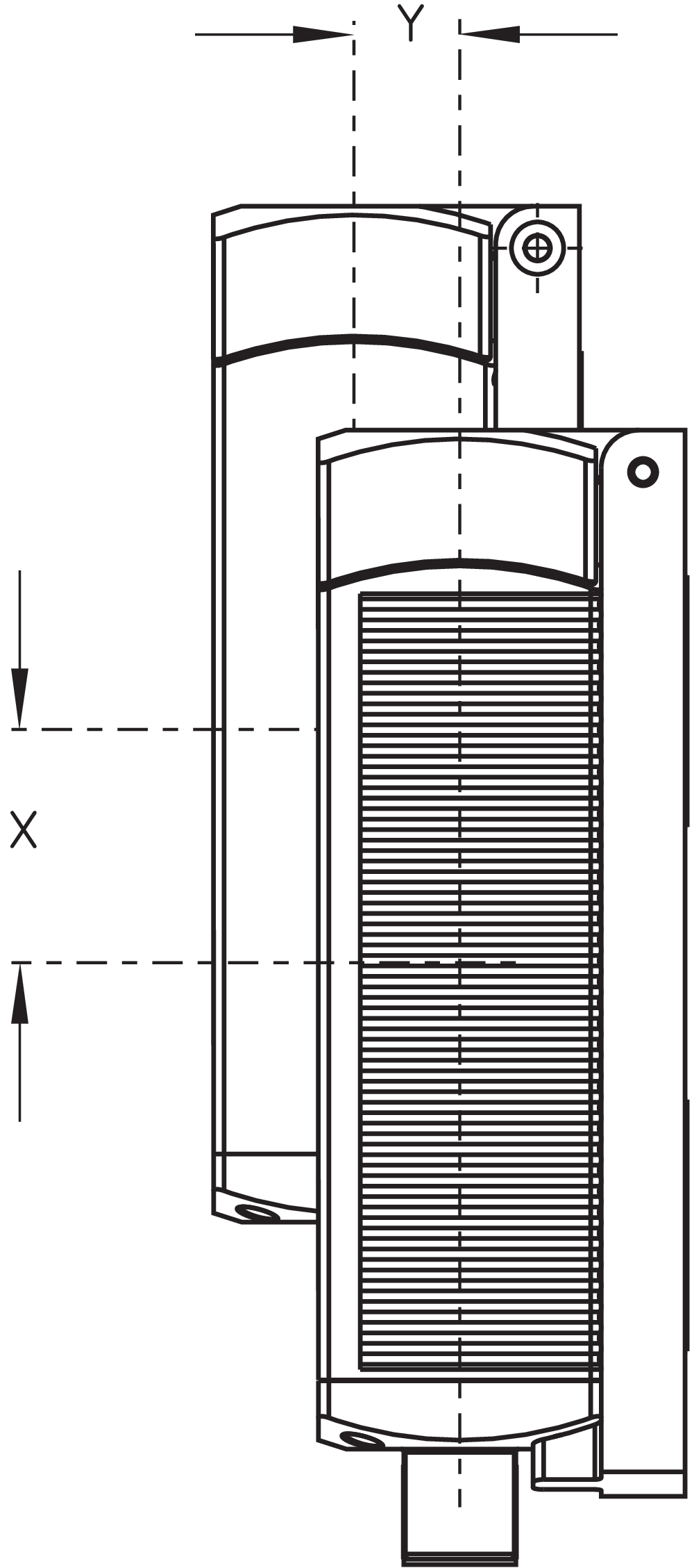
| Note (Repeat accuracy R) |
Axial offset: The long side allows for a maximum height misalignment (x) of sensor and actuator of 36 mm (e.g. mounting tolerance or due to guard door sagging). Increased misalignment, max. 53 mm, possible when the CST 34-S-2 actuator is used. The axial misalignment (y) is max. ± 10 mm (see figure: Operating principle) |
Mechanical data - Connection technique
| Note (length of the sensor chain) |
Cable length and cross-section change the voltage drop dependiing on the output current |
| Note (series-wiring) |
Unlimited number of devices, oberserve external line fusing, max. 31 devices in case of serial diagnostic SD |
| Length of cable |
2 m |
| Termination |
Cable (Y-UL 2517), 8-pole |
| Cable section, maximum |
8 x 0.35 mm² |
| Wire cross-section |
22 AWG |
| Cable type |
LiYY |
Mechanical data - Dimensions
| Length of sensor |
35 mm |
| Width of sensor |
27 mm |
| Height of sensor |
108.2 mm |
Ambient conditions
| Degree of protection |
IP65 IP67 |
| Ambient temperature |
-25 ... +70 °C |
| Storage and transport temperature |
-25 ... +85 °C |
| Resistance to vibrations |
10 … 55 Hz, amplitude 1 mm |
| Restistance to shock |
30 g / 11 ms |
| Protection class |
II |
Ambient conditions - Insulation values
| Rated insulation voltage Ui |
32 VDC |
| Rated impulse withstand voltage Uimp |
0.8 kV |
| Overvoltage category |
III |
| Degree of pollution |
3 |
Electrical data
| No-load supply current I0, typical |
100 mA |
| Operating current |
600 mA |
| Required rated short-circuit current |
100 A |
| Switching frequency, approx. |
3 Hz |
Electrical data - Safety digital outputs
| Rated operating current (safety outputs) |
250 mA |
| Output current, (fail-safe output), maximum |
0.25 A |
| Design of control elements |
p-type |
| Voltage drop Ud, maximum |
0.5 V |
| Leakage current Ir, maximum |
0.5 mA |
| Voltage, Utilisation category DC-12 |
24 VDC |
| Current, Utilisation category DC-12 |
0.25 A |
| Voltage, Utilisation category DC-13 |
24 VDC |
| Current, Utilisation category DC-13 |
0.25 A |
Electrical data - Diagnostic outputs
| Design of control elements |
p-type |
| Voltage drop Ud, maximum |
5 V |
Electrical data - Serial diagnostic SD
| Designation, Serial diagnostic SD |
OUT |
| Operation current |
150 mA |
| Design of control elements |
short-circuit proof, p-type |
| Wiring capacitance |
50 nF |
Electrical data - Electromagnetic compatibility (EMC)
| Interfering radiation |
IEC 61000-6-4 |
| EMC rating |
IEC 61000-6-2 |
Pin assignment
| PIN 1 |
A1 Ue Brown |
| PIN 2 |
X1 Safety input 1 White |
| PIN 3 |
A2 GND Blue |
| PIN 4 |
Y1 Safety output 1 Black |
| PIN 5 |
SD serial diagnostic output: Grey |
| PIN 6 |
X2 Safety input 2 violet |
| PIN 7 |
Y2 Safety output 2 red |
| PIN 8 |
IN serial diagnostic input Pink |
Scope of delivery
| Scope of delivery |
Actuator must be ordered separately. |
Accessory
| Recommendation (actuator) |
CST 34-S-2 CST 34-S-3 CST 180-1 CST 180-2 CST 34-S-1 |
| Recommended safety switchgear |
PROTECT PSC1 SRB-E-301ST SRB-E-201LC |
Note
| Note (General) |
Evaluation requirements: dual-channel safety input, suitable for p-type sensors with NO function. The safety-monitoring module must tolerate internal functional tests of the sensors with cyclic switch-off of the sensor outputs for max. 0.5 ms. Short-circuit recognition by the evaluation is not necessary. |
Language filter
Datasheet
Operating instructions and Declaration of conformity
TÜV certification
BG-test certificate
UL Certificate
UKCA certificate
Wiring example (electr. wiring)
Brochure
Download the latest version of Adobe Reader
Product picture (catalogue individual photo)
Dimensional drawing basic component
Operating principle
Clipart
Video ID: SD-Interface-Mr-Safety


101190025 CSS-T-A
- Accessories for series-wiring with serial diagnostics
- for CSS 34
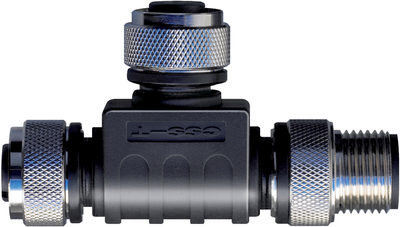
101190026 CSS-T
- Accessories for series-wiring with serial diagnostics
- for Sensors

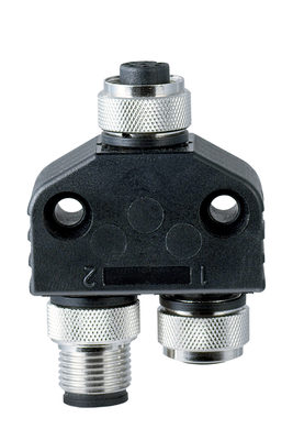
101209414 CSS-Y-A-8P
- Accessories for series-wiring with serial diagnostics
- The connector supplies the safety channels with operating voltage.
103008718 CSS-Y-A-8P-VA
- Accessories for series-wiring with serial diagnostics
- The connector supplies the safety channels with operating voltage.
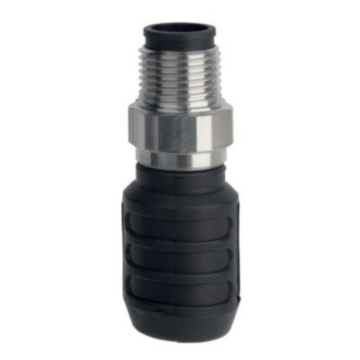
103009361 SD-Y-POWER
- Accessories for series-wiring with serial diagnostics
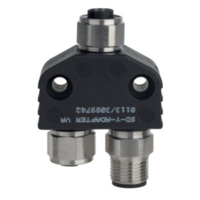
103009362 SD-Y-POWER VA
- Accessories for series-wiring with serial diagnostics

101209416 CSS-Y-8P
- Accessories for series-wiring with serial diagnostics
103008717 CSS-Y-8P-VA
- Accessories for series-wiring with serial diagnostics
101181085 CST 34-S-1
- Actuation from side

101196101 CST 34-S-2
- Actuator with double solenoid
- for increased misalignment
- Front and lateral actuation of the sensor possible
101203434 CST 34-S-3
- Front and lateral actuation of the sensor possible
- small body

103009970 SRB-E-201LC
- Plug-in screw terminals with coding
- STOP 0 Function
- 1 oder 2-channel control
- Start button / Auto-start
- 2 Safety outputs 2 A
- 1 Signalling output

103009973 SRB-E-204ST
- Plug-in screw terminals with coding
- STOP 0 Function
- Monitoring of 4 sensors
- Start button / Auto-start
- 2 Safety outputs
- 4 Signalling outputs

103007672 SRB-E-301ST
- Plug-in screw terminals with coding
- STOP 0 Function
- 1 oder 2-channel control
- Start button / Auto-start
- 1 Auxiliary contact
- 3 safety contacts
Schmersal Ltd., Sparrowhawk Close, WR14 1GL Malvern
The details and data referred to have been carefully checked. Images may diverge from original. Further technical data can be found in the manual. Technical amendments and errors possible.
Generated on: 27/04/2024, 04:12