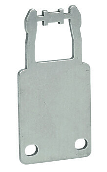
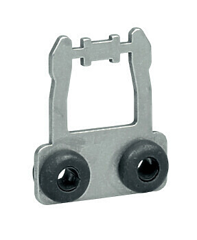
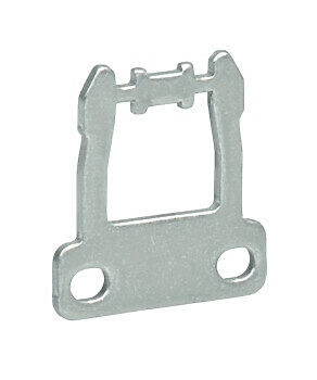
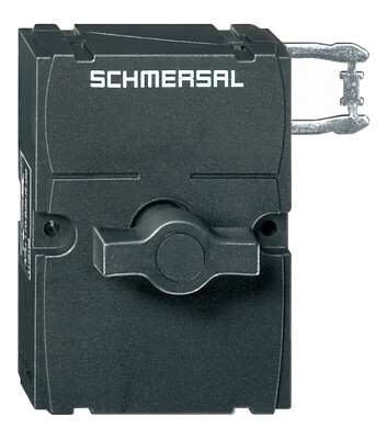
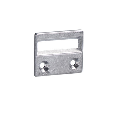
EX-AZM 170-11ZRKA-R/P-3GD
EX-AZM 170-11ZRKA-R/P-3GD
| Product type description: EX-AZM 170-(1)Z(2)K(3)-24VAC/DC-(4)-3G/D |
| (1) | |
| 11 | 1 NO contact/1 NC contact |
| 02 | 2 NC contact |
| (2) | |
| without | Latching force 5 N |
| R | Latching force 30 N |
| (3) | |
| without | Power to unlock |
| A | Power to lock |
| (4) | |
| without | Manual release |
| 1637 | Gold-plated contacts |
- IDC method of termination
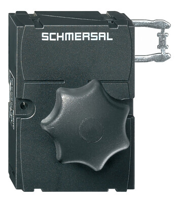
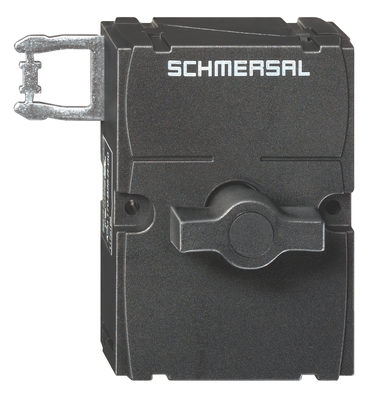
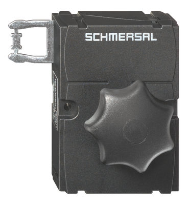
- Manual release
- Explosion protection for ATEX Zones 2 and 22
- 1 Cable entry M 20 x 1.5
- Interlock with protection against incorrect locking.
- High holding force
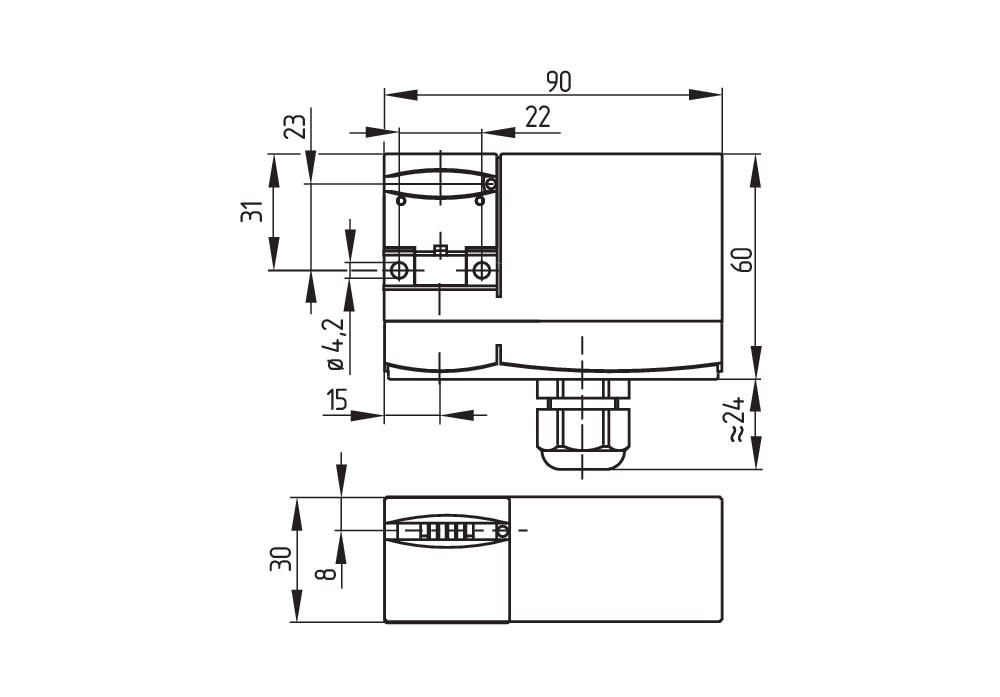
- 90 mm x 84 mm x 30 mm
Ordering data
| Product type description |
EX-AZM 170-11ZRKA-R/P-3GD |
| Article number (order number) |
103049508 |
| EAN (European Article Number) |
4030661624884 |
Approvals - Standards
| Certificates |
ATEX (Konformitätserklärung) |
Explosion protection
| Explosion protection: regulations |
EN IEC 60079-0 EN IEC 60079-15 EN 60079-31 |
| Explosion protection zones |
2 22 |
| Explosion protection category |
3G 3D |
| Explosion protection designation |
D II 3G Ex nC IIB T5 Gc X D II 3D Ex tc IIIC T80°C Dc X |
| Manufacturer declaration |
ATEX Zone 2 and 22 |
General data
| Standards |
EN IEC 60947-5-1 |
| Working principle |
electromechanical |
| Housing material |
Plastic, glass-fibre reinforced thermoplastic, self-extinguishing |
General data - Features
| Power to lock |
Yes |
| Manual release |
Yes |
| Number of auxiliary contacts |
1 |
| Number of safety contacts |
1 |
| Safety classification |
| Vorschriften |
EN ISO 13849-1 |
| Performance Level, up to |
c |
| Category |
1 |
| B10D Normally-closed contact (NC) |
2,000,000 Operations |
| Note |
Electrical life on request. |
| B10D Normally-open contact (NO) |
1,000,000 Operations |
| Mission time |
20 Year(s) |
| Safety classification - Fault exclusion |
| Performance Level, up to |
d |
| Category |
3 |
| Note |
for 2-channel use and with suitable logic unit. |
| Mission time |
20 Year(s) |
Mechanical data
| Mechanical lifetime, minimum |
1,000,000 Operations |
| Impact energy, maximum |
7 J |
| Holding force |
1,000 N |
| Latching force |
30 N |
| Positive break travel |
11 mm |
| Positive break force, minimum |
8.5 N |
| Actuating speed, maximum |
1 m/s |
| Mounting |
Screws |
| Type of the screw head |
Flat head screw |
| Tightening torque of the fastening screws for the housing cover, minimum |
0.4 Nm |
| Tightening torque of the fastening screws for the housing cover, maximum |
0.5 Nm |
| Tightening torque of the cable gland |
4.5 Nm |
Mechanical data - Connection technique
| Termination |
IDC method of termination |
| Cable cross-section of the cable glands, minimum |
6.5 mm |
| Cable cross-section of the cable glands, maximum |
12 mm |
| Cable section, minimum |
2 x 1.0 mm², flexible |
| Cable section, maximum |
1 x 1 mm², flexible |
Mechanical data - Dimensions
| Length of sensor |
30 mm |
| Width of sensor |
90 mm |
| Height of sensor |
84 mm |
Ambient conditions
| Degree of protection |
IP67 |
| Ambient temperature |
-15 ... +45 °C |
| Note (Relative humidity) |
non-condensing non-icing |
Ambient conditions - Insulation values
| Rated insulation voltage Ui |
250 VAC |
| Rated impulse withstand voltage Uimp |
4 kV |
Electrical data
| Thermal test current |
2 A |
| Rated control voltage |
24 VAC |
| Rated control voltage |
24 VDC |
| Utilisation category AC-15 |
230 VAC |
| Utilisation category AC-15 |
2 A |
| Utilisation category DC-13 |
24 VDC |
| Utilisation category DC-13 |
2 A |
| Electrical power consumption, maximum |
10 W |
| Switching element |
NO contact, NC contact |
| Switching principle |
Slow action |
| Maximale Schalthäufigkeit |
1,000 /h |
| Material of the contacts, electrical |
Silver |
Electrical data - Magnet control
| Magnet switch-on time |
100 % |
| Test pulse duration, maximum |
5 ms |
| Test pulse interval, minimum |
50 ms |
Scope of delivery
| Scope of delivery |
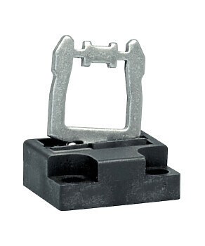
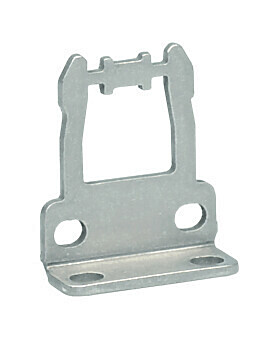
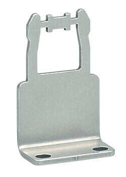
Actuator must be ordered separately. Including Ex-certified screwed cable gland and screw plug |
Note
| Note (General) |
This type termination (IDC) method enables simple connetion of flexible conductors without the need for the use of conductor ferrules |
| Note (Manual release) |
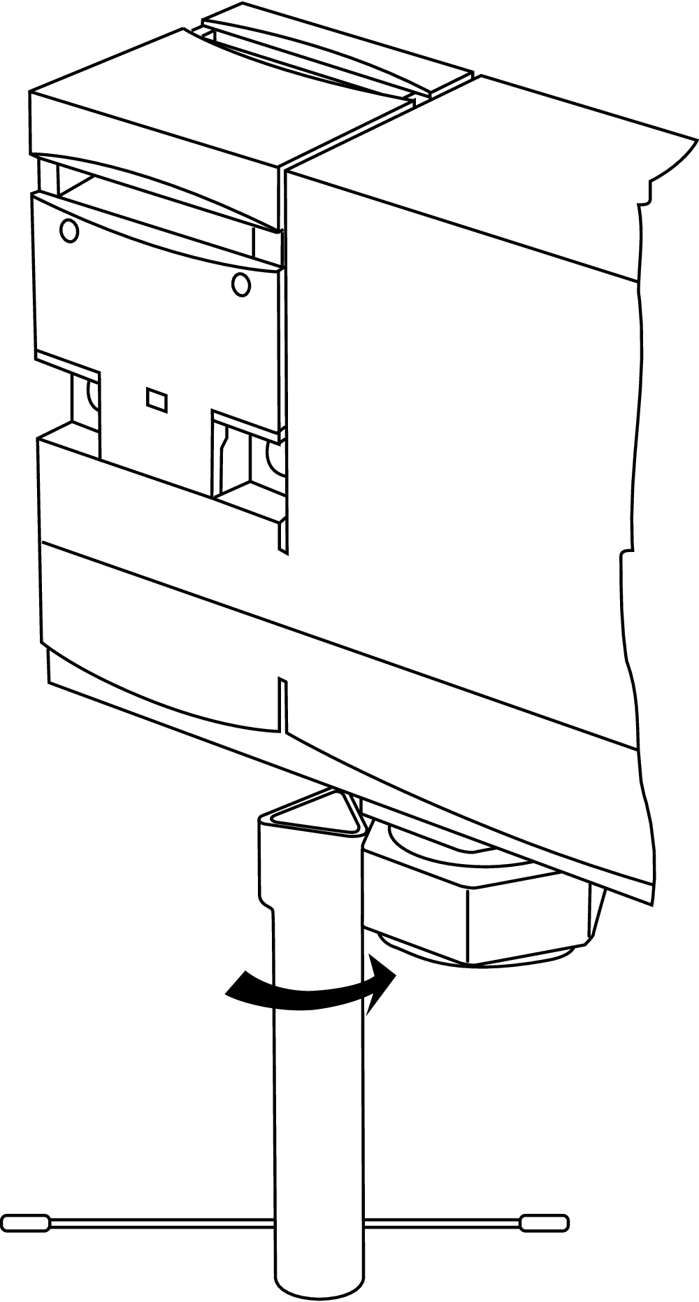
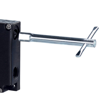
bottom For manual release using M5 triangular key, available as accessory |
Language filter
Datasheet
Operating instructions and Declaration of conformity
SISTEMA-VDMA library
Download the latest version of Adobe Reader
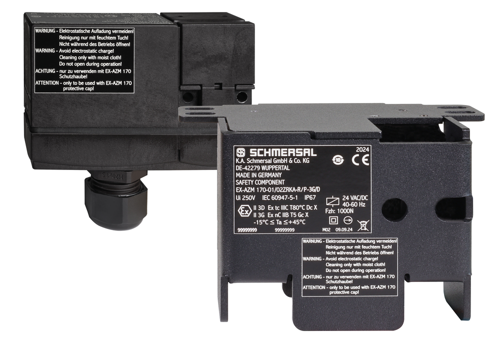
Product picture (catalogue individual photo)
Dimensional drawing basic component
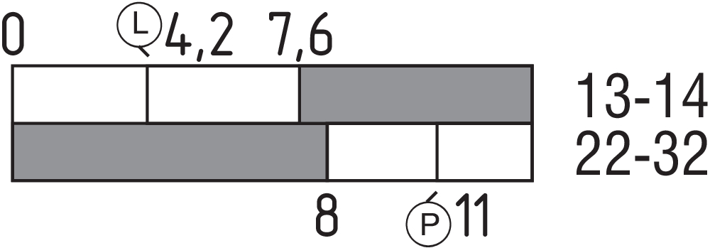
Switch travel diagram
Diagram
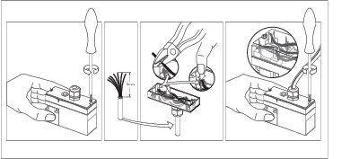
Assembly example
ID: kazm1m06
Operating principle
| EU Declaration of Conformity |  |
| Original | K.A. Schmersal GmbH & Co. KG Möddinghofe 30 42279 Wuppertal Germany Internet: www.schmersal.com |
| Declaration: | We hereby certify that the hereafter described components both in their basic design and construction conform to the applicable European Directives. |
| Name of the component: | EX-AZM170 EX-AZM170 I |
| Type: | See ordering code |
| Marking: | D II 3G Ex nC IIB T5 Gc D II 3D Ex tc IIIC T80°C Dc |
| Description of the component: | Interlocking device with electromagnetic interlock for safety functions |
| Relevant Directives: | Machinery Directive | 2006/42/EC |
| EMC-Directive | 2014/30/EU | |
| Explosion Protection Directive (ATEX) | 2014/34/EU | |
| RoHS-Directive | 2011/65/EU |
| Applied standards: | EN 60947-5-1:2017 + AC:2020 EN ISO 14119:2014 EN IEC 60079-0:2018 + AC:2020 EN IEC 60079-15:2019 EN 60079-31:2014 |
| Person authorised for the compilation of the technical documentation: | Oliver Wacker Möddinghofe 30 42279 Wuppertal |
| Place and date of issue: | Wuppertal, April 23, 2025 |
 |
| Authorised signature Philip Schmersal Managing Director |
Schmersal India Pvt. Ltd., Plot No - G-7/1, Ranjangaon MIDC, Tal. - Shirur, Dist.- Pune 412 220
The details and data referred to have been carefully checked. Images may diverge from original. Further technical data can be found in the manual. Technical amendments and errors possible.
Generated on: 14/08/2025, 12:29 pm
.png?id=497683c97d2c2689df20070a5453bdbb)

