MZM 120 BM ST2-SD2PRE-A

MZM 120 BM ST2-SD2PRE-A
| Product type description: MZM 120 (1)ST2-(2)RE-A |
| (1) | |
| B | Actuator monitored |
| BM | Combined monitoring of actuator and solenoid interlock |
| (2) | |
| 1P2PW2 | 1 diagnostic output and 2 safety outputs, p-type and combined diagnostic signal: guard system closed and interlock locked. |
| SD2P | serial diagnostic output and 2 p-type safety outputs |
- Guard locking monitored
- connector plug M12, 8-pole
- Power to lock
- serial diagnostic output
- enabling signal, when safety guard closed and locked (without force monitoring)
- Thermoplastic enclosure
- Safety switches must be used as end stop
- 40 mm x 179 mm x 40 mm
- Electronic contact-free, coded system
- Variably adjustable latching
- 3 LEDs to show operating conditions
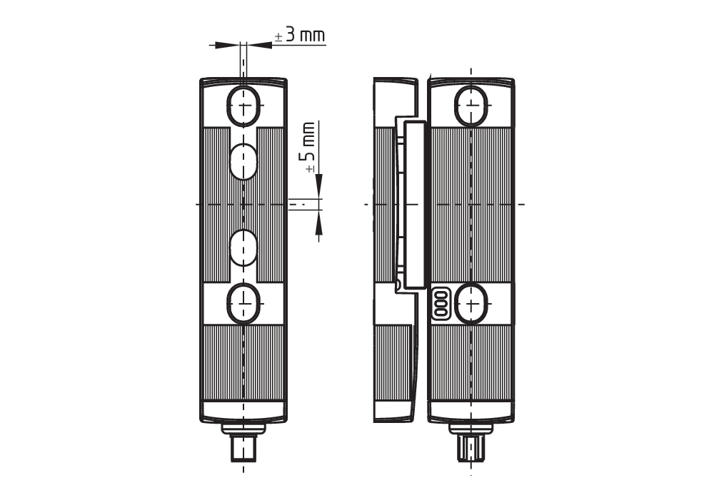
- Sensor technology permits an offset between actuator and interlock of ± 5 mm vertically and ± 1,5 mm horizontally
- Intelligent diagnosis
- Self-monitoring series-wiring
Ordering data
| Note (Delivery capacity) |
Not available! |
| Product type description |
MZM 120 BM ST2-SD2PRE-A |
| Article number (order number) |
101215717 |
| EAN (European Article Number) |
4030661419343 |
| eCl@ss number, version 12.0 |
27-27-26-03 |
| eCl@ss number, version 11.0 |
27-27-26-03 |
| eCl@ss number, version 9.0 |
27-27-26-03 |
| ETIM number, version 7.0 |
EC002593 |
| ETIM number, version 6.0 |
EC002593 |
Approvals - Standards
| Certificates |
cULus |
General data
| Standards |
EN ISO 13849-1 EN IEC 60947-5-3 EN IEC 61508 |
| Working principle |
inductive |
| Housing material |
Glass-fibre, reinforced thermoplastic |
| Reaction time, maximum |
150 ms |
| Duration of risk, maximum |
150 ms |
| Gross weight |
150 g |
General data - Features
| Power to lock |
Yes |
| Actuator monitored |
Yes |
| Solenoid interlock monitored |
Yes |
| Serial diagnostics |
Yes |
| Latching |
Yes |
| Short circuit detection |
Yes |
| Cross-circuit detection |
Yes |
| Safety functions |
Yes |
| Integral system diagnostics, status |
Yes |
| Number of safety contacts |
2 |
| Safety classification |
| Vorschriften |
EN IEC 60947-5-3 EN IEC 61508 |
| PFH value |
4.30 x 10⁻⁹ /h |
| Mission time |
20 Year(s) |
Safety classification - Interlocking function
| Performance Level, up to |
e |
| Category |
4 |
| Safety Integrity Level (SIL), suitable for applications in |
3 |
Mechanical data
| Mechanical life, minimum |
1,000,000 Operations |
| Note (Mechanical life) |
Operations for door weights ≤ 5 kg |
| Holding force |
500 N |
| Latching force, minimum |
30 N |
| Latching force, maximum |
80 N |
Mechanical data - Connection technique
| Note (length of the sensor chain) |
Cable length and cross-section change the voltage drop dependiing on the output current |
| Note (series-wiring) |
Unlimited number of devices, oberserve external line fusing, max. 31 devices in case of serial diagnostic SD |
| Termination |
Connector plug M12, 8-pole |
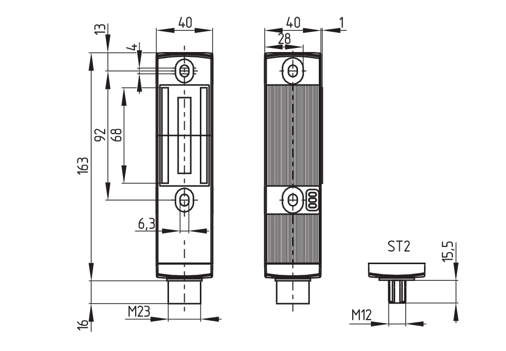
Mechanical data - Dimensions
| Length of sensor |
40 mm |
| Width of sensor |
40 mm |
| Height of sensor |
177.5 mm |
Ambient conditions
| Degree of protection |
IP67 IP69K |
| Ambient temperature |
-25 ... +55 °C |
| Storage and transport temperature |
-25 ... +85 °C |
| Relative humidity, minimum |
30 % |
| Relative humidity, maximum |
95 % |
| Note (Relative humidity) |
non-condensing non-icing |
| Resistance to vibrations |
10 … 150 Hz, amplitude 0.35 mm |
| Restistance to shock |
30 g / 11 ms |
| Protection class |
II |
Ambient conditions - Insulation values
| Rated insulation voltage Ui |
32 VDC |
| Rated impulse withstand voltage Uimp |
0.8 kV |
| Overvoltage category |
III |
| Degree of pollution |
3 |
Electrical data
| No-load supply current I0, typical |
600 mA |
| Operating current |
1,000 mA |
| Time to readiness, maximum |
4,000 ms |
| Switching frequency, approx. |
1 Hz |
| Electrical fuse rating, maximum |
2 A |
Electrical data - Magnet control
| Switching thresholds |
-3 V … 5 V (Low) 15 V … 30 V (High) |
| Magnet switch-on time |
100 % |
Electrical data - Safety digital inputs
| Switching thresholds |
−3 V … 5 V (Low) 15 V … 30 V (High) |
| Current consumption at 24 V |
5 mA |
Electrical data - Safety digital outputs
| Rated operating current (safety outputs) |
250 mA |
| Voltage drop Ud, maximum |
1 V |
| Leakage current Ir, maximum |
0.5 mA |
Electrical data - Diagnostic outputs
| Voltage drop Ud, maximum |
2 V |
Electrical data - Serial diagnostic SD
| Designation, Serial diagnostic SD |
OUT |
| Operation current |
150 mA |
| Design of control elements |
short-circuit proof, p-type |
| Wiring capacitance |
50 nF |
Status indication
| Note (LED switching conditions display) |
Operating condition: LED green Error / functional defect: LED red Supply voltage UB available: LED green |
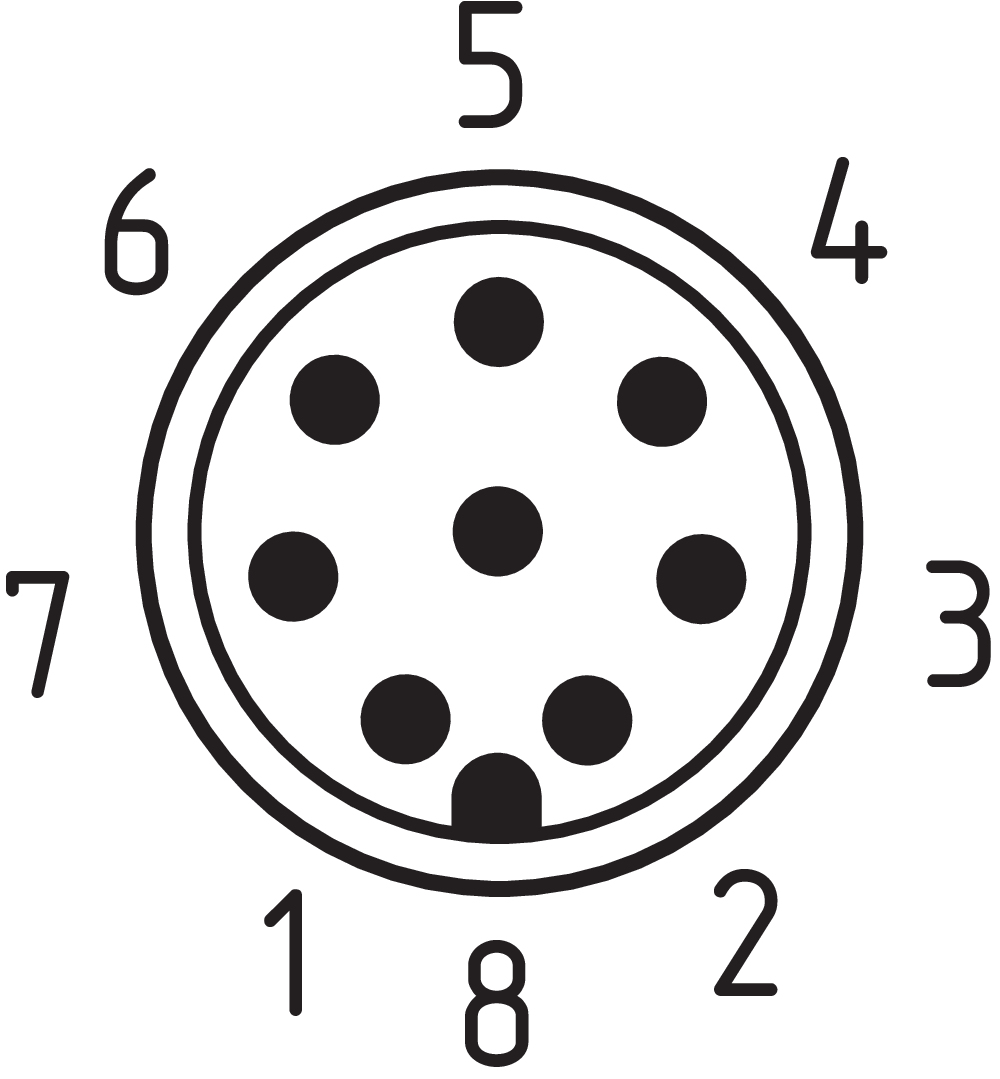
Pin assignment
| PIN 1 |
A1 Supply voltage UB |
| PIN 2 |
X1 Safety input 1 |
| PIN 3 |
A2 GND |
| PIN 4 |
Y1 Safety output 1 |
| PIN 5 |
OUT serial diagnostic output |
| PIN 6 |
X2 Safety input 2 |
| PIN 7 |
Y2 Safety output 2 |
| PIN 8 |
IN serial diagnostic input |
| PIN 9 |
without function |
Scope of delivery
| Scope of delivery |
Actuator must be ordered separately. |
Accessory
| Recommendation (actuator) |
MZM 120-B1.1 |
Note
| Note (General) |
As long as the safety guard remains closed, the unlocked safety guard can be relocked. In this case, the safety outputs are re-enabled, so that the safety guard must not be opened. |
Language filter
Datasheet
Operating instructions and Declaration of conformity
UL Certificate
SISTEMA-VDMA library
Download the latest version of Adobe Reader
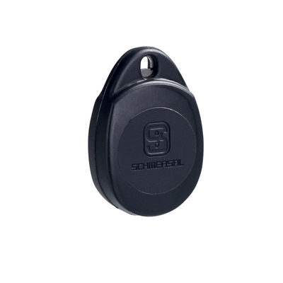
Product picture (catalogue individual photo)
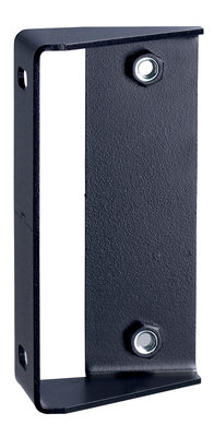
Dimensional drawing basic component
Dimensional drawing actuator
Contact arrangement
Video ID: SD-Interface-Mr-Safety

101210642 MZM 100 TARGET
- for the variable setting of the latching force
- gradually adjustable by steps of approx. 10 N within a range from approx. 30 N to 100 N
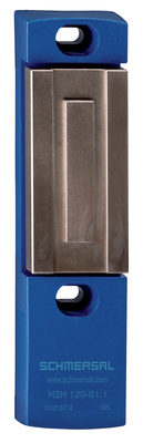
101215712 MZM 120-B1.1
- actuator free from play
- neutralisation of undesired noises
- Metal components with hygiene-compliant NEDOX® SF-2 coating

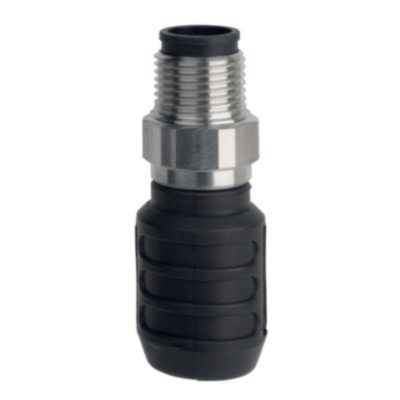
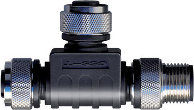
101209414 CSS-Y-A-8P
- Accessories for series-wiring with serial diagnostics
- The connector supplies the safety channels with operating voltage.
103008718 CSS-Y-A-8P-VA
- Accessories for series-wiring with serial diagnostics
- The connector supplies the safety channels with operating voltage.
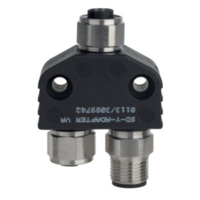
103009361 SD-Y-POWER
- Accessories for series-wiring with serial diagnostics
103009362 SD-Y-POWER VA
- Accessories for series-wiring with serial diagnostics
101190026 CSS-T
- Accessories for series-wiring with serial diagnostics
- for Sensors

101190025 CSS-T-A
- Accessories for series-wiring with serial diagnostics
- for CSS 34

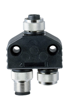
101209416 CSS-Y-8P
- Accessories for series-wiring with serial diagnostics
103008717 CSS-Y-8P-VA
- Accessories for series-wiring with serial diagnostics
K.A. Schmersal GmbH & Co. KG, Möddinghofe 30, 42279 Wuppertal
The details and data referred to have been carefully checked. Images may diverge from original. Further technical data can be found in the manual. Technical amendments and errors possible.
Generated on: 05/08/2025, 19:29