Safety-related tactile sensor
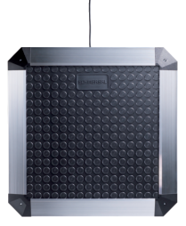
SMS 4
- Robust design
- Modular switching mat system
- Special sizes are available on request
- Maintenance free
- Simple mounting
- Slip-free surface
- High resistance to chemicals
- No additional terminating resistor required
- No additional baseplate
- 4-wire connecting cable
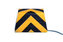
SMS 5
- with moulded ramp profile 30 mm
- Robust design
- Modular switching mat system
- Special sizes are available on request
- Maintenance free
- Simple mounting
- Slip-free surface
- High resistance to chemicals
- No additional terminating resistor required
- No additional baseplate
- 2 x 2-wire connecting cable
Safety edges
- Dirt and moisture in the profile are to a great extent compensated
- Insensitive to environmental conditions
Switching cushion
- Switching cushion to monitor flight passenger stairs, passenger boarding bridges, catering vehicles
- Incorporation of amplitude of loaded transfer platforms
Application:
Tactile monitoring systems stop the hazardous movement in case of contact or when touched. The variety of application fields require different safety devices.
Safety edges
The safety edges of the SE range are suitable for safe-guarding crushing and shearing points, that can be present on guards, lifting tables and platforms, mobile storage shelving, operating process tables, storage lifts, lift doors, loading ramps, lifting and tilting devices or industrial gates. They immediately stop the dangerous movement, thus preventing physical injury or material damage.
Safety flaps
Wide material input or feed areas on machines require a different approach to the protection of operating personnel and the machines themselves. Here, Safety flaps SL 300 are used.
Safety mats
Safety mats are an additional form of protection for machines and plants, with the area in front of the danger zone fitted with the SMS switch mat. Depending on the shape of the area to be protected, multiple safety mats can be laid in line and electrically connected. When the safety mat is actuated, a signal is evaluated and the machine stop is initiated.
In combination with a suitable connected safety monitoring module, the three above-described systems achieve control category 3 respectively 1 or 4 to ISO 13849-1.
Design and mode of operation:
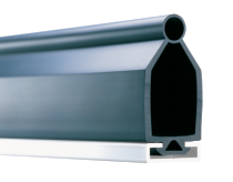
The SE range safety edges consist of 3 basis elements, i.e. an aluminium profile, a rubber profile and a pair of plug-in sensors.
The deformation of the rubber profile safety edge is evaluated. The centrepiece is a fail-safe transmitter and receiver unit in both ends of the rubber profile. The deformation of the rubber profile strip weakens or interrupts the IR-signal between the transmitter and receiver units. The connected safety monitoring module evaluates the reduction of the IR signal and stops the hazardous movement. This measurement procedure, i.e. in conjunction with a connected safety monitoring module, complies with the safety requirements of control category 4 to ISO 13849-1. Solutions for applications of category 1 are also available.
EN 13856-2 resumes the requirements for safety edges and describes their design and homologation. Safety-related properties, such as operating temperature ranges, response times, forces, operating distances and stopping distances are defined in this Standard.
EN 13849-1 describes the guidelines for the design of safety-related components of the machine control.
The risk when using a local machine or unit must be determined. The requirements on the safety of the controller increases the higher the risk.
The safety edge system of the SE range with a connected safety monitoring module of the SE-400 C range complies with the safety requirements of control category 4. Even if there are 2 errors in the system, the safety edge will ensure a safe and efficient standstill of the machine or unit.
For applications of control category 1 to ISO 13849-1 the SE range safety edge can be connected to a safety monitoring module of the SE-100 C range.
When using a safety edge, it must be ensured that the speed of the hazardous movement is lower than the maximum starting speed of the safety edge. The stopping distance of the potentially dangerous parts and the profile-specific data must be adapted to each another. The stopping distance must not only be sufficient to bring the machine in the worst case situation to a standstill, but the maximum allowable force for vulnerable body parts must not be exceeded. Attention must be made during the planning to the counter-edge. If the possible run-on distance of the selected switch strip is not sufficient, the stopping distance of the machine must be shortened or a different switch strip profile should be used.
The required minimum run-on distance must be designed with the safety factor of at least 1.2. The safety factor must be even greater as soon as the run-on distance is influenced by other machine elements. (See also EN 13856-2 Annex C.)
SL 300 safety flaps consist of a flap and carrier profile and a position switch class 1. The actuation of the flap profile causes a positive break of the position switch, thus switching off the corresponding machine drive.
SMS 4/5 safety mats include 2 separate current carrying steel plates. The plates are held apart by insulating strips. The construction is moulded in Plastisol, a mechanically robust plastic that is highly resistant to chemicals.
Upon actuation of the safety mat, the inner steel plates are slightly bent. This causes an electrical short-circuit. This electrical short-circuit is evaluated by a downstream safety-monitoring module, which immediately initiates the machine shutdown.