AZM40Z-ST-1P2P (Test)

- 超小型、薄型設計
- 119,5 mm x 40 mm x 20 mm
- 高保持力 2000 N
- ラッチ力 40 N
- 要求に基づいた無効化防止のためのRFID技術
- ロック時引抜強度(EN ISO 14119準拠)
- ヒンジ式ドアにもスライド式ドアにもたった1つのバージョン
- アクチュエーターは、180度の角度内で挿入方向を選びません
- 左右対称で取り付けはボルトで固定可能
注文データ
| Product type description |
AZM40Z-ST-1P2P (Test) |
| EAN(欧州部品番号) |
4030661535128 |
| eCl@ss番号、バージョン12.0 |
27-27-26-03 |
| eCl@ss番号、バージョン11.0 |
27-27-26-03 |
| eCl@ss番号、バージョン9.0 |
27-27-26-03 |
| ETIM番号、バージョン7.0 |
EC002593 |
| ETIM番号、バージョン6.0 |
EC002593 |
一般データ
| 規格 |
EN ISO 13849-1 EN ISO 14119 EN IEC 60947-5-3 EN IEC 61508 |
| 一般情報 |
ユニバーサルコード化 |
| Coding level according to EN ISO 14119 |
Low |
| アクティブ原理 |
RFID |
| 周波数帯、RFID |
125 kHz |
| 送信機出力 RFID、最大 |
-6 dB/m |
| ハウジング 材質 |
Light alloy die cast and plastic (glass-fibre reinforced thermoplastic) |
| 応答時間、最大 |
100 ms |
| リスク持続時間、最大 |
200 ms |
| 入力の応答時間、最大 |
1.5 ms |
| 総重量 |
300 g |
一般データ - 仕様
| ガードロック監視 |
Yes |
| ラッチング |
Yes |
| 手動解除 |
Yes |
| 短絡検出 |
Yes |
| 短絡監視 |
Yes |
| 直列接続 |
Yes |
| 安全機能 |
Yes |
| 一体型システム診断、状態 |
Yes |
| 安全接点数 |
2 |
安全性評価
| 規格 |
EN ISO 13849-1 EN IEC 61508 |
安全性評価 - インターロック
| Performance Level, up to |
e |
| カテゴリー |
4 |
| PFH値 |
1.10 x 10⁻⁹ /h |
| PFD値 |
8.90 x 10⁻⁵ |
| 安全インテグリティレベル (SIL), 安全度水準に適合 |
3 |
| Mission time |
20 年 |
安全性評価 - ガードロック
| Performance Level, up to |
d |
| カテゴリー |
2 |
| PFH値 |
3.00 x 10⁻⁹ /h |
| PFD値 |
2.40 x 10⁻⁴ |
| Safety Integrity Level (SIL), suitable for applications in |
2 |
| Mission time |
20 年 |
機械的データ
| インターロック原理 |
双安定 |
| 機械的寿命,ロッキングサイクル、 |
1,000,000 操作 |
| 機械的寿命, アクチュエ |
200,000 操作 |
| EN ISO 14119 に準拠したクロック時引抜強度 |
2,000 N |
| ロック時引抜強度, 最大 |
2,600 N |
| ラッチ力 |
40 N |
| 注意 (ラッチ力) |
+/- 25% |
| 作動速度, 最大 |
0.5 m/s |
| 取り付け |
取り付け穴 カウントシンク |
| Type of the fixing screws |
2x M5 |
| 取り付けネジの締め付けトルク、最小 |
4 Nm |
Mechanical data - Switching distances
| 確実な切替距離「ON」 |
1 mm |
| 確実な切替距離「OFF」 |
8 mm |
| 注記 (動作距離) |
All switching distances in accordance EN IEC 60947-5-3 |
機械的データ - 電気機械式
| センサーチェーンの長さ、最大 |
30 m |
| 注意(センサーチェーンの長) |
ケーブル長とケーブル径により、出力電流による電圧降下が変化します。 |
| 注意 (直列接続) |
無制限のデバイス数,外部ラインヒューズオーバーサーブ、シリアル診断SDの場合、最大31デバイス。 |
| 端子 コネクター |
M12コネクター, 8芯, Aコード化 |
機械的データ - 寸法
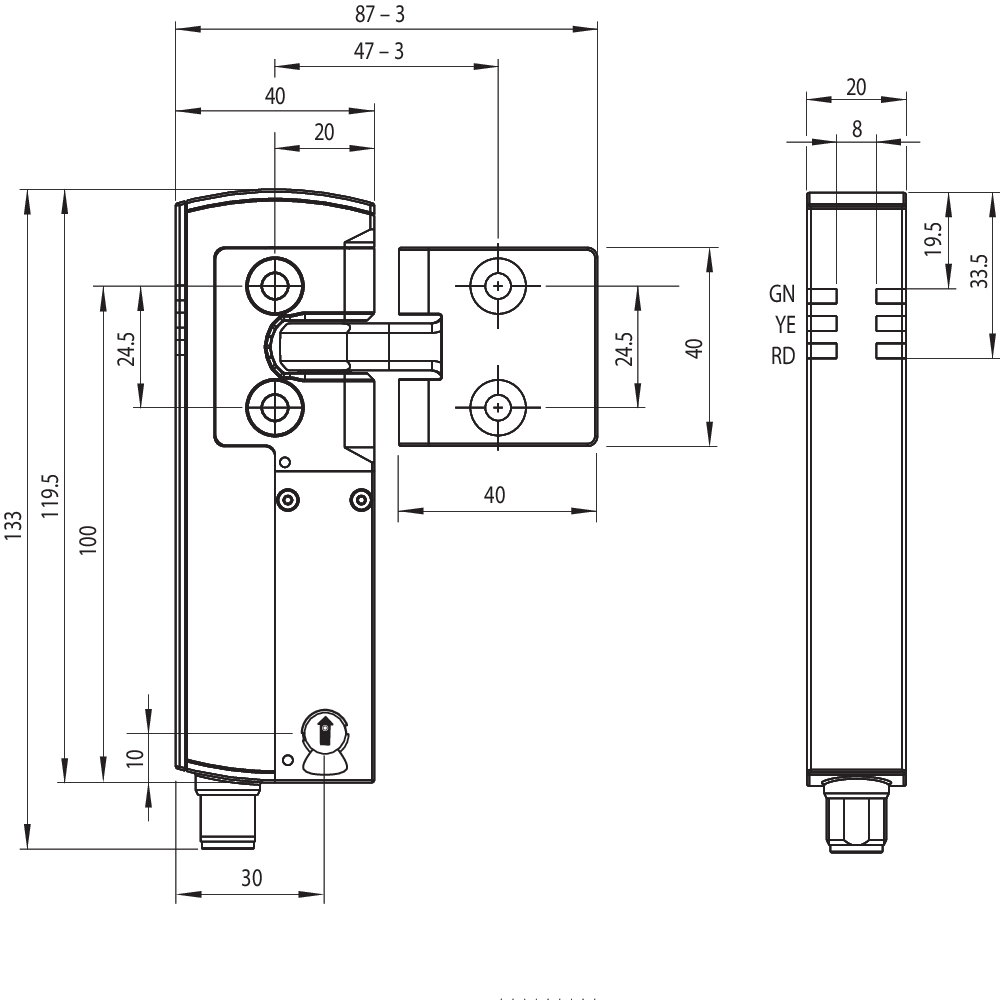
| センサー長 |
119.5 mm |
| センサーの幅 |
40 mm |
| センサーの高さ |
20 mm |
環境条件
| 保護等級 |
IP66 IP67 |
| 使用周囲温度 |
+0 ... +55 °C |
| 保管および輸送温度 |
-40 ... +85 °C |
| 相対湿度, 最大 |
93 % |
| Note (Relative humidity) |
non-condensing non-icing |
| 耐振動 |
10 ~ 55 Hz, 振幅 1 mm |
| 耐衝撃 |
30 g / 11 ms |
| Protection class |
III |
| Permissible installation altitude above sea level, maximum |
2,000 m |
環境条件 - 絶縁値
| 定格絶縁電圧 |
32 VDC |
| 定格インパルス耐電圧 |
0.8 kV |
| Overvoltage category |
III |
| 汚染度 |
3 |
電気的データ
| 動作電圧 |
24 VDC -15 % / +10 % (PELV電源により安定化) |
| 無負荷供給電流 I0, 典型的 |
100 mA |
| スイッチング時の消費電流磁石、ピーク |
600 mA / 100 ms |
| 定格動作電圧 |
24 VDC |
| 動作電流 |
1,200 mA |
| 要求定格短絡電流 |
100 A |
| 外部ワイヤとデバイスのヒューズ定格 |
2 A gG |
| 準備時間、最大 |
4,000 ms |
| 開閉頻度、最大 |
0.25 Hz |
| 使用カテゴリー DC-12 |
24 VDC / 0.05 A |
| 電気的ヒューズ定格、最大 |
2 A |
電気的データ - ソレノイド制御
| Designation, Magnet control |
IN |
| マグネット入力のスイッチングの閾値 |
-3 V … 5 V (Low) 15 V … 30 V (High) |
| マグネット起動時間 |
100 % |
| テストパルス幅、最大 |
5 ms |
| テストパルス間隔、最小 |
40 ms |
| Classification ZVEI CB24I, Sink |
C0 |
| Classification ZVEI CB24I, Source |
C1 C2 C3 |
| 24Vの時の消費電流、最小 |
10 mA |
| 24Vの時の消費電流、最大 |
15 mA |
Electrical data - Safety digital inputs
| Designation, Safety inputs |
X1 and X2 |
| フェイルセーフ入力のスイッチングの閾値 |
−3 V … 5 V (Low) 15 V … 30 V (High) |
| 24Vの時の安全入力の消費電流 |
5 mA |
| テストパルス幅、最大 |
1 ms |
| テストパルス間隔、最小 |
100 ms |
| Classification ZVEI CB24I, Sink |
C1 |
| Classification ZVEI CB24I, Source |
C1 C2 C3 |
Electrical data - Safety digital outputs
| Designation, Safety outputs |
Y1 and Y2 |
| 定格動作電流(安全出力) |
250 mA |
| 安全出力 |
short-circuit proof, p-type |
| Voltage drop Ud, maximum |
2 V |
| Leakage current Ir, maximum |
0.5 mA |
| Voltage, Utilisation category DC-12 |
24 VDC |
| Current, Utilisation category DC-12 |
0.25 A |
| Voltage, Utilisation category DC-13 |
24 VDC |
| Current, Utilisation category DC-13 |
0.25 A |
| テストパルス間隔、標準 |
1000 ms |
| テストパルス幅、最大 |
0.5 ms |
| Classification ZVEI CB24I, Source |
C2 |
| Classification ZVEI CB24I, Sink |
C1 C2 |
電気的データ - 診断出力
| Designation, Diagnostic outputs |
OUT |
| Design of control elements |
short-circuit proof, p-type |
| Voltage drop Ud, maximum |
2 V |
| Voltage, Utilisation category DC-12 |
24 VDC |
| Current, Utilisation category DC-12 |
0.05 A |
| Voltage, Utilisation category DC-13 |
24 VDC |
| Current, Utilisation category DC-13 |
0.05 A |
状態表示
| Note (LED switching conditions display) |
Operating condition: LED green Error / functional defect: LED red Supply voltage UB: LED green |
ピン配列
| PIN 1 |
A1 Supply voltage UB |
| PIN 2 |
X1 Safety input 1 |
| PIN 3 |
A2 GND |
| PIN 4 |
Y1 Safety output 1 |
| PIN 5 |
OUT Diagnostic output |
| PIN 6 |
X2 Safety input 2 |
| PIN 7 |
Y2 Safety output 2 |
| PIN 8 |
IN Solenoid control |
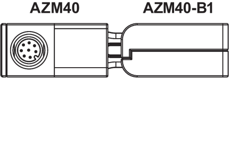
アクセサリー
| 推奨(アクチュエーター) |
AZM40-B1 |
言語フィルター
データシート
Operating instructions and Declaration of conformity
Brochure
SISTEMA-VDMA library
Adobe Readerの最新版をダウンロードしてください
Product picture (catalogue individual photo)
Dimensional drawing basic component
Dimensional drawing basic component

Video ID: AZM40
Product information: Solenoid interlock with guard locking series AZM40 (Vimeo)

Video ID: Mr-Safety-AZM40
Mr. Safety: Product presentation AZM40 (Youtube)
Mr. Safety: Product presentation AZM40 (Vimeo)
Video ID: AZM40-GID-AWARD
GID Award 3. Platz (Vimeo)
Table of Contents
- 1 この文書について
- 1.1 機能
- 1.2 取扱説明書の対象グループ: 認定された有資格者
- 1.3 使用記号の説明
- 1.4 適切な使用
- 1.5 安全上のご注意
- 1.6 誤使用に関する警告
- 1.7 免責事項
- 2 製品内容
- 2.1 型番
- 2.2 特殊仕様
- 2.3 目的
- 2.4 技術データ
- 3 取り付け
- 3.1 通常の取り付け方法
- 3.2 マニュアルリリース
- 3.3 外形図
- 4 電気配線
- 4.1 電気配線上のご注意
- 4.2 接続する安全制御機器の要求事項
- 4.4 配線例
- 5 アクチュエータのティーチング / アクチュエータ検出
- 6 動作原理と診断機能
- 6.1 ソレノイド制御
- 6.2 バージョン毎の安全出力の動作
- 6.3 診断用LED
- 6.4 診断出力
- 6.5 診断情報
- 7 立ち上げと保全
- 7.1 機能テスト
- 7.2 メンテナンス
- 8 取り外し・廃棄
- 8.1 取り外し
- 8.2 廃棄処分
1 この文書について
1.1 機能
本書は、本製品の安全な操作と解体のために、取付け、セットアップ、試運転に必要なすべての情報を提供します。装置に同封されている取扱説明書は、読み易い状態で、完全版を機器の付近に保管してください。
1.2 取扱説明書の対象グループ: 認定された有資格者
この取扱説明書に記述された全ての操作は、使用者によって認められた専門技術者が行ってください。
この取扱説明書を熟読し、コンポーネントの据付及び運転の前に、労働安全及び事故予防のための適用可能な全規定に付いてご確認ください。
組み立て作業員は、コンポーネントの選定、取り付け、内蔵に対して、他の技術仕様を遵守するのと同じように、慎重に整合規格を選択しなければなりません
1.3 使用記号の説明
- 情報、助言、注釈:この表示は役立つ追加情報を示します。
- 注意: 取り扱いを誤った場合に、故障、機能不良が想定される内容を示しています。
警告:取り扱いを誤った場合に、傷害を負う可能性が想定される内容、及び物的損害の発生が想定される内容を示しています。
1.4 適切な使用
シュメアザールが提供する製品は、個人消費者向けではありません。
本製品は、設備や機械の一部として安全関連機能を果たすために開発されたものです。設備や機械全体が適格に動作する事を保証する事は、製造者の責任です。
セーフティスイッチは下記に挙げられたバージョン、又は製造者によって許可されたアプリケーションに対してのみ使用しなければなりません。アプリケーションの範囲に関する詳細は、「製品内容」の項を参照ください。
1.5 安全上のご注意
ユーザーはこの取扱説明書に記載されている、安全上の説明、各国の設置基準、並びに全ての周知の安全規則や事故防止規則を遵守しなければなりません。
- 詳細な技術情報に付いてはシュメアザールカタログ、又はインターネット(products.schmersal.com)上のオンラインカタログをご参照下さい。
仕様などの記載内容について予告なく変更する事があります。あらかじめご了承ください
取付、据付、操作及び保全に関する説明書と同様に安全に関する注意が遵守されていれば、残留リスクはありません。
1.6 誤使用に関する警告
- 本製品に対する不適切な使い方や、無効化により、人への危険や機械設備への損傷を招く事があります。
1.7 免責事項
誤った取り付けやこの取扱説明書を正しく理解していないために起こった損害、故障は、Schmersalの免責事項となります。また、製造者に許可されていない代替・付属品による損害は、製造者の免責事項となります。
安全上の理由から、デバイスに対する独自の変更や不適切な修理、部品の交換や改造は厳として認められず、それが理由で発生した故障や事故に対し、シュメアザールは責任を一切負いません。
2 製品内容
2.1 型番
| 製品タイプの説明: AZM40(1)-(2)-ST-1P2P-(3) |
| (1) | |
| Z | ロック監視 > |
| B | アクチュエーター監視 |
| (2) | |
| なし | 標準コード化 |
| I1 | 個別コード化 |
| I2 | 個別コード化 複数のティーチング |
| (3) | |
| なし | 皿ネジ用座繰り (標準) |
| PH | 突き出しネジ用平ハウジング |
| アクチュエータ | AZM40-B1 |
| AZM40-B1-PH |
2.2 特殊仕様
型式記号で挙げられていない特別仕様は一般使用に準じます。
2.3 目的
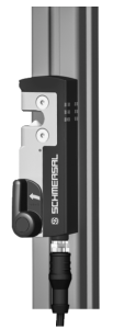
非接触式セーフティスイッチは、安全回路での用途向けに設計されており、可動ガードの位置やロック状態の監視に使用されます。
AZM40インターロックシステムは、40 mmプロファイルシステムへの取り付けに適しており、またアクチュエータ挿入口における180度の柔軟性により、ヒンジドアやスライドドアにも適しています。LED表示灯は3方向より視認可能です。
- セーフティスイッチは、EN ISO 14119に基づきタイプ4のインターロック機器に分類されます。個別コード化の仕様ではコード化レベルHighに分類されます。
電磁ロック機能及びインターロック機能付きのセーフティスイッチとして種々のタイプを使用できます。
- リスク分析の結果、監視されたインターロックの使用が必要とされる場合は、 > のシンボル付きで表示されるインターロック監視タイプの製品を使用してください。
アクチュエータ監視機種 (B) は工程保護のためのインターロック機能を持つセーフティスイッチです。
安全機能により、ガードが開いていると安全出力はOFFとなり、ガードが開いている間はOFFの状態を維持します。
電磁ロック付きインターロックAZM40は双安定性システムなので、電源が落ちた時にはその時点の位置を維持します。
直列接続
直列接続ができます。直列接続の場合、リスク時間は変わらず、反応時間は、技術データで指定された追加ユニットごとの入力の反応時間の合計だけ増加します。コンポーネントの数は、技術データに基づく外部ケーブルヒューズ保護と、ケーブル損失によってのみ制限されます。
- 使用者は、関連規格と要求される安全レベルに基づいてセーフティチェーンを評価し、設計しなければなりません。複数のセーフティセンサーがある場合、装置個々のPFH値は加算されなければなりません。
- セーフティコンポーネントが組み込まれた制御システムの全体的な構想は、関連規格に対して妥当性を確認しなければなりません。
2.4 技術データ
一般データ
| 規格 |
EN ISO 13849-1 EN ISO 14119 EN IEC 60947-5-3 EN IEC 61508 |
| 一般情報 |
ユニバーサルコード化 |
| Coding level according to EN ISO 14119 |
Low |
| アクティブ原理 |
RFID |
| 周波数帯、RFID |
125 kHz |
| 送信機出力 RFID、最大 |
-6 dB/m |
| ハウジング 材質 |
Light alloy die cast and plastic (glass-fibre reinforced thermoplastic) |
| 応答時間、最大 |
100 ms |
| リスク持続時間、最大 |
200 ms |
| 入力の応答時間、最大 |
1.5 ms |
| 総重量 |
300 g |
一般データ - 仕様
| ガードロック監視 |
Yes |
| ラッチング |
Yes |
| 手動解除 |
Yes |
| 短絡検出 |
Yes |
| 短絡監視 |
Yes |
| 直列接続 |
Yes |
| 安全機能 |
Yes |
| 一体型システム診断、状態 |
Yes |
| 安全接点数 |
2 |
安全性評価
| 規格 |
EN ISO 13849-1 EN IEC 61508 |
安全性評価 - インターロック
| Performance Level, up to |
e |
| カテゴリー |
4 |
| PFH値 |
1.10 x 10⁻⁹ /h |
| PFD値 |
8.90 x 10⁻⁵ |
| 安全インテグリティレベル (SIL), 安全度水準に適合 |
3 |
| Mission time |
20 年 |
安全性評価 - ガードロック
| Performance Level, up to |
d |
| カテゴリー |
2 |
| PFH値 |
3.00 x 10⁻⁹ /h |
| PFD値 |
2.40 x 10⁻⁴ |
| Safety Integrity Level (SIL), suitable for applications in |
2 |
| Mission time |
20 年 |
機械的データ
| インターロック原理 |
双安定 |
| 機械的寿命,ロッキングサイクル、 |
1,000,000 操作 |
| 機械的寿命, アクチュエ |
200,000 操作 |
| EN ISO 14119 に準拠したクロック時引抜強度 |
2,000 N |
| ロック時引抜強度, 最大 |
2,600 N |
| ラッチ力 |
40 N |
| 注意 (ラッチ力) |
+/- 25% |
| 作動速度, 最大 |
0.5 m/s |
| 取り付け |
取り付け穴 カウントシンク |
| Type of the fixing screws |
2x M5 |
| 取り付けネジの締め付けトルク、最小 |
4 Nm |
Mechanical data - Switching distances
| 確実な切替距離「ON」 |
1 mm |
| 確実な切替距離「OFF」 |
8 mm |
| 注記 (動作距離) |
All switching distances in accordance EN IEC 60947-5-3 |
機械的データ - 電気機械式
| センサーチェーンの長さ、最大 |
30 m |
| 注意(センサーチェーンの長) |
ケーブル長とケーブル径により、出力電流による電圧降下が変化します。 |
| 注意 (直列接続) |
無制限のデバイス数,外部ラインヒューズオーバーサーブ、シリアル診断SDの場合、最大31デバイス。 |
| 端子 コネクター |
M12コネクター, 8芯, Aコード化 |
機械的データ - 寸法
| センサー長 |
119.5 mm |
| センサーの幅 |
40 mm |
| センサーの高さ |
20 mm |
環境条件
| 保護等級 |
IP66 IP67 |
| 使用周囲温度 |
+0 ... +55 °C |
| 保管および輸送温度 |
-40 ... +85 °C |
| 相対湿度, 最大 |
93 % |
| Note (Relative humidity) |
non-condensing non-icing |
| 耐振動 |
10 ~ 55 Hz, 振幅 1 mm |
| 耐衝撃 |
30 g / 11 ms |
| Protection class |
III |
| Permissible installation altitude above sea level, maximum |
2,000 m |
環境条件 - 絶縁値
| 定格絶縁電圧 |
32 VDC |
| 定格インパルス耐電圧 |
0.8 kV |
| Overvoltage category |
III |
| 汚染度 |
3 |
電気的データ
| 動作電圧 |
24 VDC -15 % / +10 % (PELV電源により安定化) |
| 無負荷供給電流 I0, 典型的 |
100 mA |
| スイッチング時の消費電流磁石、ピーク |
600 mA / 100 ms |
| 定格動作電圧 |
24 VDC |
| 動作電流 |
1,200 mA |
| 要求定格短絡電流 |
100 A |
| 外部ワイヤとデバイスのヒューズ定格 |
2 A gG |
| 準備時間、最大 |
4,000 ms |
| 開閉頻度、最大 |
0.25 Hz |
| 使用カテゴリー DC-12 |
24 VDC / 0.05 A |
| 電気的ヒューズ定格、最大 |
2 A |
電気的データ - ソレノイド制御
| Designation, Magnet control |
IN |
| マグネット入力のスイッチングの閾値 |
-3 V … 5 V (Low) 15 V … 30 V (High) |
| マグネット起動時間 |
100 % |
| テストパルス幅、最大 |
5 ms |
| テストパルス間隔、最小 |
40 ms |
| Classification ZVEI CB24I, Sink |
C0 |
| Classification ZVEI CB24I, Source |
C1 C2 C3 |
| 24Vの時の消費電流、最小 |
10 mA |
| 24Vの時の消費電流、最大 |
15 mA |
Electrical data - Safety digital inputs
| Designation, Safety inputs |
X1 and X2 |
| フェイルセーフ入力のスイッチングの閾値 |
−3 V … 5 V (Low) 15 V … 30 V (High) |
| 24Vの時の安全入力の消費電流 |
5 mA |
| テストパルス幅、最大 |
1 ms |
| テストパルス間隔、最小 |
100 ms |
| Classification ZVEI CB24I, Sink |
C1 |
| Classification ZVEI CB24I, Source |
C1 C2 C3 |
Electrical data - Safety digital outputs
| Designation, Safety outputs |
Y1 and Y2 |
| 定格動作電流(安全出力) |
250 mA |
| 安全出力 |
short-circuit proof, p-type |
| Voltage drop Ud, maximum |
2 V |
| Leakage current Ir, maximum |
0.5 mA |
| Voltage, Utilisation category DC-12 |
24 VDC |
| Current, Utilisation category DC-12 |
0.25 A |
| Voltage, Utilisation category DC-13 |
24 VDC |
| Current, Utilisation category DC-13 |
0.25 A |
| テストパルス間隔、標準 |
1000 ms |
| テストパルス幅、最大 |
0.5 ms |
| Classification ZVEI CB24I, Source |
C2 |
| Classification ZVEI CB24I, Sink |
C1 C2 |
電気的データ - 診断出力
| Designation, Diagnostic outputs |
OUT |
| Design of control elements |
short-circuit proof, p-type |
| Voltage drop Ud, maximum |
2 V |
| Voltage, Utilisation category DC-12 |
24 VDC |
| Current, Utilisation category DC-12 |
0.05 A |
| Voltage, Utilisation category DC-13 |
24 VDC |
| Current, Utilisation category DC-13 |
0.05 A |
状態表示
| Note (LED switching conditions display) |
Operating condition: LED green Error / functional defect: LED red Supply voltage UB: LED green |
ピン配列
| PIN 1 |
A1 Supply voltage UB |
| PIN 2 |
X1 Safety input 1 |
| PIN 3 |
A2 GND |
| PIN 4 |
Y1 Safety output 1 |
| PIN 5 |
OUT Diagnostic output |
| PIN 6 |
X2 Safety input 2 |
| PIN 7 |
Y2 Safety output 2 |
| PIN 8 |
IN Solenoid control |
安全分類に関する注意事項
- ガードロック機能の分類は、監視対象の電磁ロック付きインターロックAZM40Z-…-1P2P-… の標準機に対してのみ適用されます(型式記号参照)。
- インターロックの作動は、外部へのOSSD出力信号と比較されなければなりません。意図しないロック解除が原因でシャットダウンが発生した場合、これは外部診断によって検出されます。
- ガードロック機能の安全性分析において、電磁ロック付きインターロックAZMを完全なシステムの一部として参照しています。
障害を防止するための、安全な動作や安全な動作やケーブルの保護といった更なる方策は、ユーザー側で行わなければなりません。
ガードロックが解除されるという故障が発生した場合、これは電磁ロック付きインターロックにより検知され、安全ドアのY1/Y2がOFFします。この様な故障が発生すると、機械が安全な状態になる前に、保護機器は一度だけ直ちに開きます。カテゴリ2のシステム動作では、テストによって検知される安全機能の喪失が原因の故障がある可能性があります。
FCC/IC - 注意
このデバイスは、FCC規則のパート15に準拠しており、またカナダのイノベーション科学経済開発省のライセンス免除RSSに準拠するライセンス免除送信機/受信機が含まれています。
操作は、次の2つの条件の下で許可されます:
(1) 本装置は有害な干渉信号を発生させてはならない。
(2)本装置は干渉信号を許容できなければならない。これらの条件には、本装置が不適切に機能する原因となる干渉信号も含まれます。
本装置は、100mm以上の距離で使用される場合、神経刺激制限(ISED SPR-002)に準拠します。K.A.が明示的に承認していない変更または修正。デバイスを使用するユーザの権限を無効にする可能性があります。
この機器に含まれる免許不要の送受信機は、免許不要の無線機器に適用されるカナダ革新 科学 経済開発(ISED)当局の「無線規格仕様」の要件を満たしています。この機器に含まれる免許不要の送受信機は、免許不要の無線機器に適用されるカナダ革新 科学 経済開発(ISED)当局の「無線規格仕様」の要件を満たしています。以下の2つの条件下で動作が許可されます:
(1) 妨害電波を発生させてはならない。
(2) 本装置は、その機能を損なう可能性がある場合であっても、受信した無線周波数の干渉を許容しなければならない。
本装置は、100mm以上の距離で使用する場合、神経刺激制限(ISED CNR-102)に適合します。
Schmersal GmbH & Co. KG が明示的に承認していない変更または改造を行った場合、 ユーザーによるデバイスの使用許可は無効になる場合があります。
| 20941-22-14519 | Este equipamento nao tem direito àprotecao contra interferência prejudicial e nao pode causar interferencia em sistemas devidamente autorizados. Para maiores informacores consultar: www.gov.br/anatel |
3 取り付け
3.1 通常の取り付け方法
- EN ISO 12100, EN ISO 14119及びEN ISO 14120の記述を遵守して下さい。
取付け方向に制限はありません。.
電磁ロック付きインターロックはドアストッパとして使ってはなりません。
トランスポートロックは取り外す必要があります。

電磁ロック付きインターロックとアクチュエーターの取り付け用に、M5ネジ用の2つの取り付け穴があります。
- M5 ネジは少なくとも強度クラス 8.8、またはステンレス鋼の場合は強度クラス 80 である必要があります。M5 ネジの締め付けトルクは 4 ~ 6 Nm で、最大締め付けトルクは使用する締め付けネジによって異なります。
- 電磁ロック付きインターロックは自己潤滑式です。ロッキングボルトとアクチュエータの凹部にあるグリスは取り除かないでください。
- ボルト部分に微細な汚れがたまらないようにしなければなりません。そのため、ボルトが下から上に向かうような取り付けは好ましくありません。
また、アクチュエータは、外部からの影響による損傷から保護されるように取り付けられなければなりません。
- 氷点下の温度での使用は、ドライコールドでのみ許可されています。 使用者は、セーフティスイッチを組み立てる際にこれを考慮に入れる必要があります。
- ロッキングボルト付きインターロック(A)と三角マーク付きアクチュエータ(B)は、同じ取り付け方向に取り付けなければなりません。

アクチュエーター方向
アクチュエータは180度どこからでも挿入できます。

- アクチュエータはガードに確実に取り付け、適切な方法(無効化防止ネジ、接着、ネジヘッドをつぶすなど)により取り外しが出来ないようにしなければなりません。
アクチュエータとインターロックのオフセット
| 傾斜角度 | 回転角度 |
|---|---|
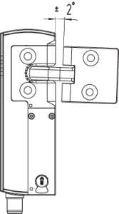 |  |
| 動作方向と開閉距離 | ||
|---|---|---|
| AZM40は以下の公差範囲内で動作しなければなりません: | ||
| X 軸 | - 3 mm |  |
| Y 軸 | ± 1 mm | |
| Z 軸 | ± 1.5 mm (アクチュエータセンタ位置において) | |
調整
2本の六角穴付きネジM4は、六角レンチAF 2 mmを使用して、アクチュエータをX方向に調整するために使用できます。
六角穴付きネジM4による調整

- 六角穴付きネジは完全に緩めないでください。
このようなシステム特有の障害、干渉や動作距離の減少を避けるために、次のガイドラインを遵守してください。
- 電磁ロック付きインターロックとアクチュエータの領域の金属部品と磁界は、スイッチング距離に影響を与えたり、誤動作を引き起こしたりする可能性があります
- 金属片を近付けないでください。
AZM40 機器間の最小間隙(mm)

3.2 マニュアルリリース
機械の設置やメンテナンス時に、本製品は非通電状態でロック解除できます。マニュアルリリースを反時計回りに回すと、インターロックが解除されます。 マニュアルリリースを元の位置に戻せば、通常の電磁ロックの動作に戻ります。
- マニュアルリリースをストッパーの位置以上には回さないでください。
マニュアルリリースを作動させるためにはツールが必要です。(推奨:マイナスドライバー0.8 x4…4.5mm)
マニュアルリリースは、偶発的な作動から保護する必要があります。 試運転完了後、同封のシールを使用してください。
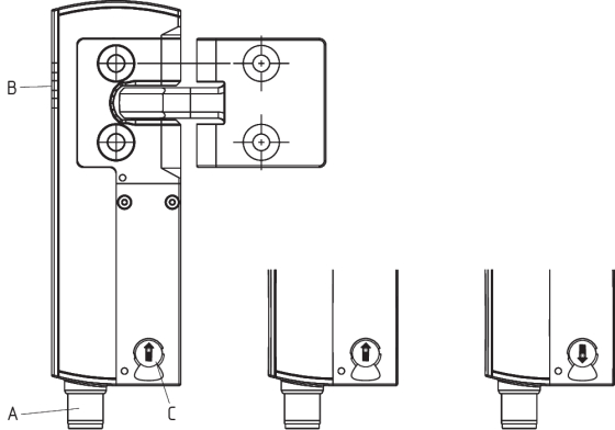
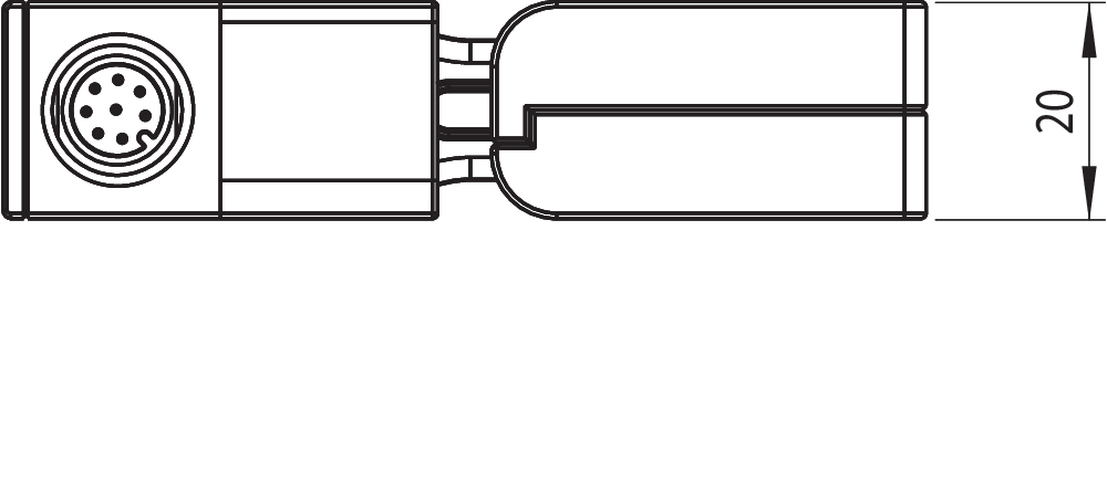
| 記号説明 | |
|---|---|
| A | M12 コネクタ, 8芯 |
| B | LED表示 |
| C | C: マニュアルリリース (両面) |
 | 電磁ロック付きインターロック 有効 |
 | 磁ロック付きインターロック 無効 |
3.3 外形図
全ての寸法表記はmm

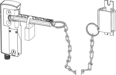
後付けキット 緊急脱出/緊急リリース
後付けキットは、電磁ロック付きインターロックの後付けの機能拡張に使用します。
| 型式 | 品番 | |
|---|---|---|
| 緊急脱出 | ACC-AZM40-LEV-T | 103054265 |
| 緊急解除 | ACC-AZM40-LEV-N | 103054268 |
| 緊急脱出 押しボタン -40 mm プロファイル用 -170 mmまでのプロファイル用 | ACC-AZM40-PT-T-40MM ACC-AZM40-PT-T-170MM | 103054271 103054273 |
| 緊急リリース 押しボタン -40 mm プロファイル用 -170 mmまでのプロファイル用 | ACC-AZM40-PT-N-40MM ACC-AZM40-PT-N-170MM | 103054275 103054277 |
| ACC-AZM40-LEV | ACC-AZM40-PT |
|---|---|
 | 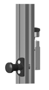 |
| 型式 | 品番 | |
|---|---|---|
| ロックアウト機器 | SZ40 | 103053182 |
| ユニバーサ取付プレート、20、30、45、50、60mmプロファイルシステム用、2個入り | MP-AZM40 | 103045324 |
| 無効化防止ネジキット M5 x 25, 皿ネジ 2 pcs. | ACC-NRS-M5X25-FHS-2PCS | 103045415 |
| 無効化防止ネジキット M5 x 25, 皿ネジ 2 pcs. | ACC-NRS-M5X25-CSS-2PCS | 103045416 |
| SZ40 | MP-AZM40 |
|---|---|
 |  |
4 電気配線
4.1 電気配線上のご注意
- 電気配線は専門技術者が非通電の状態で行って下さい。
電圧入力 A1、X1、X2、IN端子は過電圧から保護されなければなりません。EN 60204-1に基づく電源ユニットを推奨します。
必要なケーブルのヒューズ保護を設置時に統合する必要があります。
安全出力は制御システムの安全回路に接続出来ます。
4.2 接続する安全制御機器の要求事項
2チャンネル安全入力、2つのPNPタイプ半導体出力に適します (OSSD)
- セーフティコントローラの構成
安全開閉装置が電子安全監視モジュールに接続されている場合は、少なくとも 100 ミリ秒の不一致時間を設定することをお勧めします。 安全監視モジュールの安全入力は、約1秒のテスト インパルスをブランキングできなければなりません。安全監視モジュールはクロスワイヤショート監視機能を持つ必要はありませんが、必要に応じてクロスワイヤショート監視機能を無効にする必要があります。
- 適切なセーフティリレーユニットの選択に関する情報は、Schmersalのカタログか、インターネット (products.schmersal.com) 上にあるオンラインカタログをご覧ください。
| セーフティスイッチの機能 | コネクタのピン配列 | シュメアザール配線番号のカラーコードコネクタープラグ | EN 60947-5-2に基づく市販のコネクタのカラーコード | |||
|---|---|---|---|---|---|---|
| 従来の診断機能付き |  | P67 / IP69 DIN 47100に基づく | IP69 (PVC) | |||
| A1 | Ue | 1 | 白 | 茶 | 茶 | |
| X1 | 安全入力 1 | 2 | 茶 | 白 | 白 | |
| A2 | GND | 3 | 緑 | 青 | 青 | |
| Y1 | 安全出力 1 | 4 | 黄 | 黒 | 黒 | |
| OUT | 診断出力 | 5 | 灰 | 灰 | 灰 | |
| X2 | 安全入力 2 | 6 | ピンク | 紫 | ピンク | |
| Y2 | 安全出力 2 | 7 | 青 | 赤 | 紫 | |
| IN | ソレノイド制御 | 8 | 赤 | ピンク | 橙 | |
アクセサリ: 配線済みケーブル
| ソケット付きケーブル (メス) M12, 8芯 - 8 x 0.25 mm², IP67 / IP69 | |
|---|---|
| ケーブル長 | 品番 |
| 2.5 m | 103011415 |
| 5.0 m | 103007358 |
| 10.0 m | 103007359 |
| 15.0 m | 103011414 |
| Connecting cables (PVC) with socket (female) M12, 8-pole - 8 x 0.21 mm², IP69 | |
|---|---|
| ケーブル長 | 品番 |
| 5.0 m | 101210560 |
| 5.0 m, アングル | 101210561 |
| 10.0 m | 103001389 |
| 15.0 m | 103014823 |
その他のケーブル長やアングル付きケーブル引き出しタイプはリクエストにより提供可能です。
- アングルコネクタを使用する場合は、取り付け面と平行に位置合わせし、アクチュエータとは反対側に配線します。
4.4 配線例
アプリケーション例を提示します。個々のアプリケーションに対して、スイッチ類やそのセットアップが適切かどうか、注意深くチェックしなければなりません。アプリケーション例を提示します。
配線例: AZM40の直列接続
電源は接続されたセーフティスイッチの最終(リレーユニットを基準として)で両方の安全入力にインプットされます。最初のセーフティコンポーネントの安全出力は、セーフティリレーユニットに接続されます。

Y1 と Y2 = 安全出力 → 安全リレーユニット
5 アクチュエータのティーチング / アクチュエータ検出
標準コード化された電磁ロック付きインターロックは納入後直ぐに使用できます。
個別コード化された電磁ロック付きインターロックとアクチュエータは以下のティーチング工程が必要です。
- 電磁ロック付きインターロックの電源供給を遮断し、再投入してください。
- アクチュエータを検出領域に導きます。ティーチングの手順が電磁ロック付きインターロックのLED、緑OFF、赤ON、黄色点滅(1 Hz)で示されます。
- 10秒後に黄色LEDが短い(3 Hz)点滅で、電磁ロック付きインターロックの動作電圧の遮断を要求します。(5分以内に遮断されない場合、電磁ロック付きインターロックはティーチング行程を中断し、5回の赤色点滅によりアクチュエータのエラーを表示します)
- 動作電圧が再投入された後、ティーチングされたコードを有効にするために、アクチュエーターをもう一度検出する必要があります。それにより動作中のコードは、最終的に記録されます。 (製品型式I2にて、新規アクチュエータのティーチング時は下記を参照ください)
suffix -I1の要求により、セーフティスイッチとアクチュエータの組み合わせは変更する事は出来ません。
型式末尾が -I2の場合、新しいアクチュエータでの「ティーチング」手順は制限なく繰り返す事が出来ます。新規アクチュエータのティーチング時に、これまでのコードは無効となります。その後、10分間ティーチングプロセス不可となり、より高度な無効化防止が保証されます。緑色LEDはティーチング行程不可の期間中点滅し、その後新規アクチュエータは検出されます。時間経過中に電源遮断が発生した場合、10分間の無効化保護時間が起動します。
6 動作原理と診断機能
6.1 ソレノイド制御
双安定インターロックは、IN信号(= 24 V)の動作によって解除されます。IN信号が設定されていない場合(= 0 V)、正しいアクチュエータが挿入されている間は,電磁ロック付きインターロックはロック状態になります。
6.2 バージョン毎の安全出力の動作
標準のAZM 40Zでは、ロック解除で安全出力はOFFになります。ロック解除されたガードは、↲アクチュエーターがAZM 40Zに挿入されている間は、再ロックが可能です。↲その場合、安全出力も再びONになります。
セーフティーガードは開けた状態にしてはいけません.
AZM40Bの場合、ガードが開けられた時のみ安全出力がOFFになります。
すでに安全出力がONしている場合、電磁ロック付インターロックの機能に直ちに影響を及ぼす事のないエラー(例:使用周囲温度の超過、安全出力異常の可能性、交差短絡)の時は、警告メッセージを発し、診断出力はOFFとなり、安全出力は遅延してOFFになります。エラーの警告が30分間続くと安全出力はOFFになります。診断出力がOFF、かつ安全出力がON状態の場合は、制御された方法で生産工程を停止させることが出来ます。エラーの修正後、対応するセーフティドアを開くことによりエラーメッセージはリセットされます。
6.3 診断用LED
電磁ロック付きインターロックは3色LEDを介してエラーを表示するだけではなく、動作状態も表示します。
| 緑 (電源) | 動作電圧ON |
| 黄 (状態) | 動作状況 |
| 赤 (故障) | エラー (表参照2: エラーメッセージ / 赤色診断LEDの点滅コード) |
緑色のLEDは、セーフティセンサーがスタンバイの状態を表示します。供給電圧がオンで、すべての安全入力が存在します。 安全入力 (X1とX2) の一方または両方の電圧が欠落している時の緑色LEDの点滅 (1Hz)
| システム状況 X1 および/または X2 に入力信号がありません | LED | ||
|---|---|---|---|
| 緑 | 赤 | 黄 | |
| 安全ガードが開いており、上流の安全回路の安全ガードも開いています | 点滅 (1Hz) | Off | Off |
| 安全ガードが閉じており、上流の安全回路の安全ガードが開いている | 点滅 (1Hz) | Off | 点滅 |
| 安全ガードがロックされ、上流の安全回路の安全ガードが開いている | 点滅 (1Hz) | Off | On |
6.4 診断出力
短絡保護のある診断出力は、表示用又はPLCなどの非安全関連制御部に使用可能です。
診断出力は安全性に関連する出力ではありません。
エラー警告
故障が発生すると、安全出力は30分後にOFFとなります(「故障」表示LED点滅、表2参照)。安全出力は当初出力状態を維持します(最大30分間)。これにより、制御された形で生産プロセスを停止することが出来ます。エラー警告は、エラーの原因が取り除かれると消えます。
エラー
電磁ロック付きセーフティドアスイッチの機能を保証できないエラー(内部エラー)が発生すると、安全出力が直ちに遮断します。セーフティドアスイッチの安全機能に直ちに影響しないエラー(使用周囲温度の超過、安全出力の干渉電位、交差短絡など)が出た場合、安全出力は遅延OFFします(表2参照)。エラーの修正後、対応するセーフティドアを開くことによりエラーメッセージはリセットされます。
- 電磁ロック付きインターロックの強制開放は、すべてのLEDの同期点滅によって示されます。 この場合、電磁ロック付きインターロックとアクチュエータを交換しなければなりません。
- 安全出力で複数のエラーが検出された場合、又はY1とY2の間で交差短絡が確認された場合、自動電子ロックが行われます。つまり通常のエラー確認は不可能です。このタイプのインターロックをリセットするには、エラーの原因を取り除いた後、電磁ロック付きインターロックを電源電圧から分離する必要があります。
アクチュエータ監視ガードロックの例による診断出力の動作
ドア閉後、ロック信号が適用された場合

ドア開時、ロック信号が適用された場合

プロセスが中断され、ドアをロック出来ないか故障の場合


 | ロック |  | ロック解除 |  | ロック時間 |
 | ドアが開いた状態 |  | ガード閉 | ||
 | ガードはロックされていないか故障 |  | ガードロック |
6.5 診断情報
| 表1: セーフティスイッチの診断情報 | |||||||
|---|---|---|---|---|---|---|---|
| システム状況 | ソレノイド制御 (双安定) IN | LED | 安全出力 Y1, Y2 | 診断出力OUT | |||
| 緑 | 赤 | 黄 | AZM40Z | AZM40B | |||
| ドアが開いた状態 | 24 V | On | Off | Off | 0 V | 0 V | 0 V |
| ドア閉、未ロック | 24 V | On | Off | 点滅 | 0 V | 24 V | 24 V |
| ドア閉、ロック不可 | 0 V | On | 点滅 2) | 点滅 | 0 V | 24 V | 0 V |
| ドア閉、ロック | 0 V | On | Off | On | 24 V | 24 V | 24 V |
| エラー警告 1) | 0 V / 24 V | On | 点滅 2) | 点滅 | 24 V / 0 V | 24 V1) | 0 V |
| エラー | 0 V / 24 V | 点滅 2) | 0 V | 0 V | 0 V | ||
| 機械的過負荷エラー3) | 0 V | 点滅 同期 | 点滅 同期 | 点滅 同期 | 0 V | 0 V | 0 V |
| 入力回路X1、X2の一方または両方のエラー | 0 V / 24 V | 点滅 | Off | S. セクション 診断用LED | システムの状態に応じて | ||
| 事前警告段階、耐用年数 (95%の耐用年数) | 0 V / 24 V | 点滅 同期 | 点滅 同期 | 点灯 / 点滅 / off | システムの状態に応じて | ||
| 最大耐用年数達成 | 0 V / 24 V | 点滅 交互 | 点滅 交互 | Off | 0 V | 0 V | 0 V |
| 仕様 I1/I2 での追加: | |||||||
| アクチュエータの教示行程開始 | 24 V | Off | On | 点滅 | 0 V | 0 V | 0 V |
| I2のみ: アクチュエーターの教示プロセス(ブロック解除) | 24 V | 点滅 | Off | Off | 0 V | 0 V | 0 V |
| 1) 30分後: エラーのためのスイッチオフ 2) s. 点滅コード 3) 機械的過負荷フォルトに関するクレームの場合、関連するアクチュエータを含む装置を必ず送付しなければならない。 | |||||||
| 表2: エラー表示 / 赤色診断LEDの点滅コード | |||
|---|---|---|---|
| 点滅コード (赤) | 型式 | 安全出力がOFFとなるまでの時間 | エラーの原因 |
| 1回点滅 | Y1出力のエラー(警告) | 30分 | 出力遮断時の出力テスト又はY1の電圧異常 |
| 2回点滅 | Y2出力のエラー(警告) | 30分 | 出力遮断時の出力テスト又はY2の電圧異常 |
| 3回点滅 | 交差短絡エラー(警告) | 30分 | 出力Y1、Y2の交差短絡または両方の出力エラー |
| 4回点滅 | 温度超過エラー(警告) | 30分 | 温度測定で内部温度の超過を感知 |
| 5回点滅 | アクチュエータのエラー | 0分 | 誤った、または欠陥のあるアクチュエータ |
| 6回点滅 | 内部エラー | 0分 | 制御入力エラー |
| 7回点滅 | インターロックエラー | 0分 | ロック阻止、ロック解除阻止及び、手動リリースの位置が正しくない(左右どちらか一方) |
| 8回点滅 | 過電圧/低電圧故障エラー (警告) | 30分 | 仕様外の電源電圧 |
| 赤色LED連続点灯 | 内部エラー | 0分 | 機器の故障 |
7 立ち上げと保全
7.1 機能テスト
セーフティコンポーネントの安全機能をテストする必要があります。 以下の条件を事前にチェックし、適合していなければなりません:
- ケーブルコネクターが確実に取り付けられているか確認
- ハウジングに損傷がないか確認
- ゴミや汚れなどを取り除いてください
7.2 メンテナンス
正しく設置され、適切に使用されていれば、セーフティスイッチはメンテナンスフリーです。
通常の目視及び機能テストに加えて、以下のチェックを推奨します。
- • アクチュエータと電磁ロック付きセーフティドアスイッチが確実に取り付けられているかを確認
- • アクチュエータユニットと電磁ロック付きインターロックの最大ミスアライメント、および最大傾斜角度と回転角度を確認し、必要であればM4ソケットネジを使用して調整する。
- ケーブルコネクターが確実に取り付けられているか確認
- ハウジングやアクチュエーターに損傷がないか確認
- ゴミや汚れなどを取り除いてください
- 例えば予備のアクチュエータを使うなどする無効化に対する保護のために、そしてガードの無効化防止のために、適切な方策を講じなければなりません。
- 破損、故障の場合は交換してください。
- 1.000.000回のロッキングサイクルまたは500.000回のアクチュエイターサイクルの耐用年数(タイププレートVerVersion 2参照)に達すると、電磁ロック付きインターロックはロックできなくなり、アクチュエータと共に交換する必要があります。
8 取り外し・廃棄
8.1 取り外し
セーフティスイッチの取り外しは非通電状態で行わなければなりません。
8.2 廃棄処分
- セーフティスイッチは国家規格や法規に従って、適切な措置により廃棄しなければなりません。
シュメアザー株式会社, 〒222-0033 横浜市港北区新横浜3-9-5, 新横浜第3東昇ビル
データと詳細は完全にチェックされました。画像は元の画像と異なる場合があります。技術的なデータはマニュアルで見られます。技術的に変更されたり、エラーの可能性があります。
Generated on 2025/06/26 3:16
最近見た製品

HWS32-BL-SW
PS216-Z02R-K210
TS 236-02Z-M20
IFL 2-8M-10P-1955 1,3M