AZM40Z-ST-1P2P (Test)

- 紧凑、扁平设计
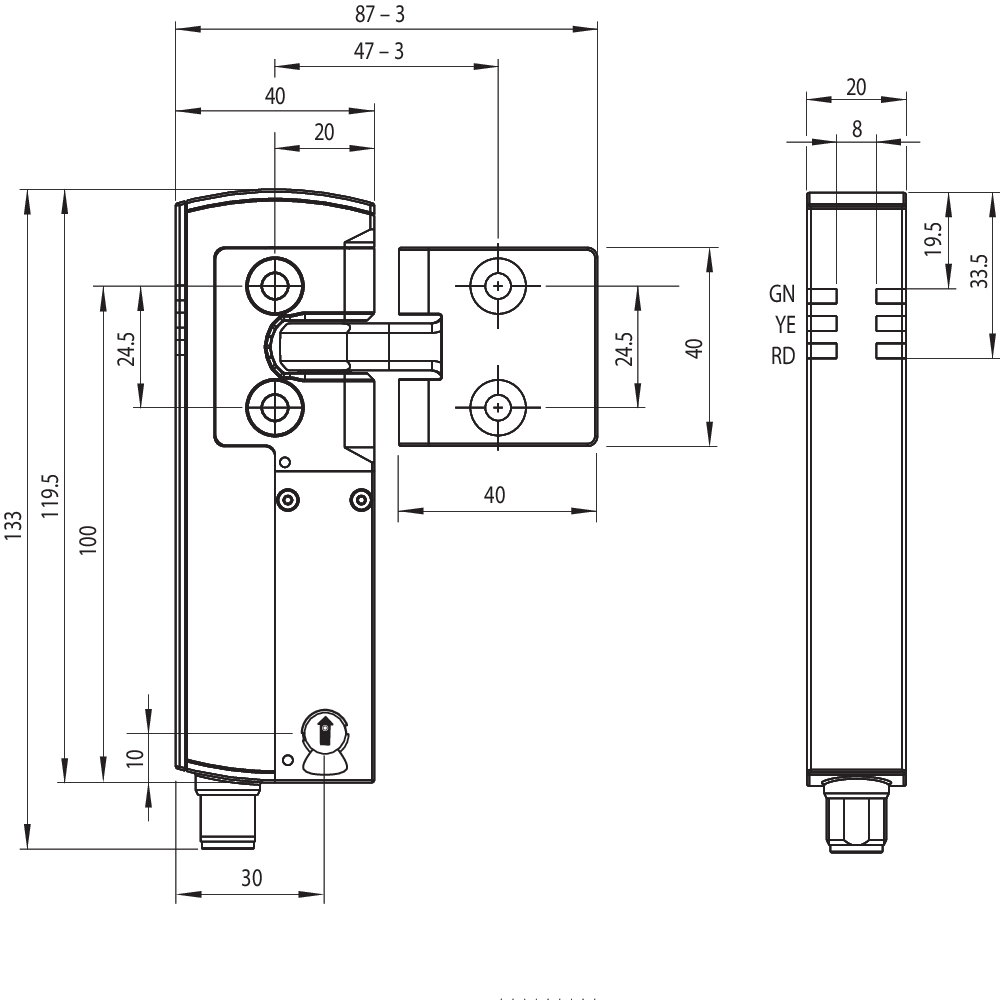
- 119,5 mm x 40 mm x 20 mm
- 高持紧力 2000 N
- 扣紧力40N
- 基于需求的防篡改RFID技术
- 编码级别“高”的独立编码版本,符合ISO 14119
- 适用铰链门和滑动门的唯一型号
- 操动件可在180度角内连续联锁。
- 对称安装,可安装在任意一侧
订货数据
| 型号 |
AZM40Z-ST-1P2P (Test) |
| EAN(欧洲商品编号) |
4030661535128 |
| eCl@aa number,版本:12.0 |
27-27-26-03 |
| eCl@aa number,版本:11.0 |
27-27-26-03 |
| eCl@aa number,版本:9.0 |
27-27-26-03 |
| ETIM 编号,7.0 版 |
EC002593 |
| ETIM 编号,6.0 版 |
EC002593 |
总体数据
| 标准型 |
EN ISO 13849-1 EN ISO 14119 EN IEC 60947-5-3 EN IEC 61508 |
| 编码 |
通用编码 |
| 编码等级,依据EN ISO 14119 |
低 |
| 工作原理 |
RFID |
| 频段 RFID |
125 kHz |
| 发射器输出 RFID, 最大植 |
-6 dB/m |
| 外壳材料 |
轻合金压铸件和塑料 (玻璃纤维增强热塑塑料,自熄灭) |
| 响应时间,最大 |
100 ms |
| 风险持续期,最大 |
200 ms |
| 响应时间,通过安全输入关闭安全输出,最大值 |
1.5 ms |
| 毛重 |
300 g |
总体数据 - 产品特性
| 电磁安全锁,受监控 |
是 |
| 锁 |
是 |
| 手动解锁 |
是 |
| 短路检测 |
是 |
| 交叉电路检测 |
是 |
| 串联连接 |
是 |
| 安全功能 |
是 |
| 整个系统检测,状态 |
是 |
| 安全触点数量 |
2 |
安全评估
| 标准型 |
EN ISO 13849-1 EN IEC 61508 |
安全评估 - 联锁
| 性能水平,最高 |
e |
| 类别 |
4 |
| PFH值 |
1.10 x 10⁻⁹ /h |
| PFD值 |
8.90 x 10⁻⁵ |
| 安全完整性等级 (SIL),停止 0,适用于以下应用 |
3 |
| 任务时间 |
20 年 |
安全评估 - 防护锁定
| 性能水平,最高 |
d |
| 类别 |
2 |
| PFH值 |
3.00 x 10⁻⁹ /h |
| PFD值 |
2.40 x 10⁻⁴ |
| 安全完整性等级 (SIL),停止 0,适用于以下应用 |
2 |
| 任务时间 |
20 年 |
机械参数
| 联锁原理 |
双稳定 |
| 机械寿命, 锁定周期 |
1,000,000 操作 |
| 机械寿命, 操动件循环 |
200,000 操作 |
| 保持力 FZh 按照 EN ISO 14119 |
2,000 N |
| 锁紧力 Fmax, 最大 |
2,600 N |
| 锁定力 |
40 N |
| 注,(闩锁力) |
+/- 25% |
| 操动速度,最大 |
0.5 m/s |
| 安装 |
安装孔 埋头孔 |
| 固定螺丝类型 |
2x M5 |
| 固定螺钉的紧锢力矩, 最低限度 |
4 Nm |
Mechanical data - Switching distances
| 肯定开关距离 "ON" Sao |
1 mm |
| 肯定闭合距离 "OFF" Sar |
8 mm |
| 注意(开关距离) |
All switching distances in accordance EN IEC 60947-5-3 |
机械参数 - 连接技术
| 传感器链长度,最大 |
30 m |
| 注意 (传感器链长度) |
根据输出电流,电缆长度和电缆截面会改变电压降 |
| 注意 (串联连接) |
设备数量不限,oberserve 外部线路熔断,最多可连接 31 台设备。在串行诊断 SD 的情况下,最多可连接 31 台设备 |
| 连接器 |
连接器M12,8芯,A编码 |
机械参数 - 尺寸
| 传感器长度 |
119.5 mm |
| 传感器宽度 |
40 mm |
| 传感器高度 |
20 mm |
环境条件
| 防护等级 |
IP66 IP67 |
| 工作环境温度 |
+0 ... +55 °C |
| 储存和运输温度 |
-40 ... +85 °C |
| 最大相对湿度 |
93 % |
| 注(相对湿度) |
无冷凝 不结冰 |
| 抗振动 |
10 ... 55 Hz,振幅 1 mm |
| 耐冲击 |
30 g / 11 ms |
| 防护等级 |
III |
| 最大允许安装海拔高度 |
2,000 m |
环境条件 - 绝缘值
| 额定绝缘电压 Ui |
32 VDC |
| 额定冲击耐受电压 Uimp |
0.8 kV |
| 过电压级别 |
III |
| 污染等级 |
3 |
电气参数
| 工作电压 |
24 VDC -15 % / +10 % (稳定PELV电源) |
| 空载电源电流 I0, 典型 |
100 mA |
| 开关瞬间的电流消耗磁铁,峰值 |
600 mA / 100 ms |
| 额定工作电压 |
24 VDC |
| 工作电流 |
1,200 mA |
| 要求额定短路电流 |
100 A |
| 外部电线和设备保险丝额定值 |
2 A gG |
| 准备就绪时间,最大 |
4,000 ms |
| 转换频率,最大 |
0.25 Hz |
| 应用类别 DC-12 |
24 VDC / 0.05 A |
| 电气保险丝容量,最大 |
2 A |
电气参数 - 线圈控制
| 指定, 线圈控制 |
IN |
| 开关阈值 |
-3 V … 5 V (Low) 15 V … 30 V (High) |
| 磁铁闭合时间 |
100 % |
| 测试脉冲持续时间, 最大 |
5 ms |
| 测试脉冲间隔, 最低限度 |
40 ms |
| 分类 ZVEI CB24I,接收器 |
C0 |
| 分类 ZVEI CB24I,信号源 |
C1 C2 C3 |
| 24V时,电流消耗,最小 |
10 mA |
| 24V时,电流消耗,最大 |
15 mA |
电子参数 - 安全数字输入
| 指定,安全输入 |
X1 和 X2 |
| 开关阈值 |
−3 V … 5 V (Low) 15 V … 30 V (High) |
| 24V时,电流消耗 |
5 mA |
| 测试脉冲持续时间, 最大 |
1 ms |
| 测试脉冲间隔, 最低限度 |
100 ms |
| 分类 ZVEI CB24I,接收器 |
C1 |
| 分类 ZVEI CB24I,信号源 |
C1 C2 C3 |
电气参数 - 安全数字输出
| 指定,安全输出 |
Y1和Y2 |
| 额定工作电流(安全输出) |
250 mA |
| 控制元件的设计 |
短路保护,P型 |
| 电压降 Ud, 最大电压降 Ud, 最大 |
2 V |
| 泄漏电流 Ir, 最大植 |
0.5 mA |
| 电压,应用类别 DC-12 |
24 VDC |
| 电流,应用类别 DC-12 |
0.25 A |
| 电压,应用类别 DC-13 |
24 VDC |
| 电流,应用类别 DC-13 |
0.25 A |
| 测试脉冲间隔,典型 |
1000 ms |
| 测试脉冲持续时间, 最大 |
0.5 ms |
| 分类 ZVEI CB24I,信号源 |
C2 |
| 分类 ZVEI CB24I,接收器 |
C1 C2 |
电气参数 - 诊断输出
| 指定, 诊断输出 |
OUT |
| 控制元件的设计 |
短路保护,P型 |
| 电压降 Ud, 最大电压降 Ud, 最大 |
2 V |
| 电压,应用类别 DC-12 |
24 VDC |
| 电流,应用类别 DC-12 |
0.05 A |
| 电压,应用类别 DC-13 |
24 VDC |
| 电流,应用类别 DC-13 |
0.05 A |
状态显示
| 注 (LED开关状态显示) |
工作状态:LED绿色 错误 / 功能故障:LED红色 供电电压 UB:LED 绿色 |
引脚分配
| PIN 1 |
A1 电源电压 UB |
| PIN 2 |
X1 安全输入 1 |
| PIN 3 |
A2 GND |
| PIN 4 |
Y1 安全输出 1 |
| PIN 5 |
OUT 监控输出 |
| PIN 6 |
X2 安全输入 2 |
| PIN 7 |
Y2 安全输出 2 |
| PIN 8 |
IN 线圈控制 |
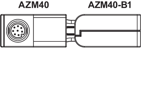
附件
| 建议(操动件) |
AZM40-B1 |
语言条件
数据表
操作指南及符合性声明
手册
SISTEMA-VDMA 数据库
下载最新版本的Adobe Reader
产品图片(单独目录照片)
尺寸图 基本组件
尺寸图 基本组件

Video ID: AZM40
Product information: Solenoid interlock with guard locking series AZM40 (Vimeo)

Video ID: Mr-Safety-AZM40
Mr. Safety: Product presentation AZM40 (Youtube)
Mr. Safety: Product presentation AZM40 (Vimeo)
Video ID: AZM40-GID-AWARD
GID Award 3. Platz (Vimeo)
清单
- 1 关于该文件
- 1.1 功能
- 1.2 目标群:拥有授权的专业人员
- 1.3 应用符号
- 1.4 用途
- 1.5 安全信息
- 1.6 警告
- 1.7 免责条款
- 2 产品描述
- 2.1 订货代码
- 2.2 特殊型号
- 2.3 用途
- 2.4 技术参数
- 3 安装
- 3.1 安装概述
- 3.2 手动解锁
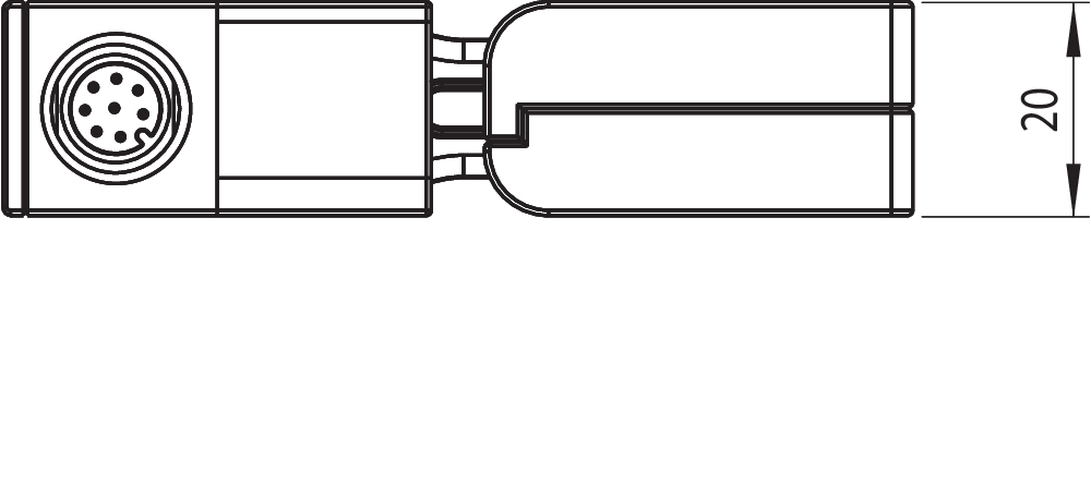
- 3.3 尺寸
- 4 电气连接
- 4.1 电气接线指示
- 4.2 连接安全监控模块的要求
- 4.3 接线配置和连接器配件
- 4.4 接线图示
- 5 操动件教学 / 操动件监测
- 6 主动原理和诊断功能
- 6.1 磁力控制
- 6.2 安全输出的工作方式
- 6.3 诊断LED
- 6.4 诊断输出
- 6.5 诊断信息
- 7 调试与维护
- 7.1 功能检查
- 7.2 维护
- 8 拆卸与处理
- 8.1 拆卸
- 8.2 处理
1 关于该文件
1.1 功能
本文件提供了安装、设置和调试所需的所有信息,以确保开关设备的安全操作和拆卸。设备附带的操作说明书必须始终保持清晰易读。
1.2 目标群:拥有授权的专业人员
本操作说明书中描述的所有操作必须由经过培训的专业人员执行,并由工厂操作员授权。
本说明书应清晰可读,并置于设备附近醒目位置。
开关的选择,安装及集成由机器制造商根据相关的法规和要求来考虑。
1.3 应用符号
- 信息,提示,说明: 该符号标示出了有用的附加信息。
- 注意:不注意这些警告提示的话可能导致失败或故障
警告:不注意这些警告提示的话可能导致身体受伤和/或机器损害。
1.4 用途
施迈赛公司的产品系列并不是为大众消费者准备的。
该产品可作为一个整体系统或机器的安全功能的一部分来使用。由系统或机器的生产者来保证系统或机器整体的运作。
该安全产品只可在满足本安装指导书所述条件或得到生产供应商允许的环境中使用。相应的应用领域的信息,请参阅章节:产品描述。
1.5 安全信息
用户必须遵守本说明书以及国家特定的安装标准,以及安全和事故预防规定中的安全指示。
- 更多的技术信息您可以通过施迈赛产品目录或者登陆施迈赛公司网址:products.schmersal.com 在线目录进行查询。
我司对所有信息不承担责任,且对技术变更权利予以保留。
在注意安全指示和注意操作说明书中个关于安装,调试,操作,维护的指示的情况下,其余风险未知。
1.6 警告
- 错误使用或操控安全开关可能导致人身伤害,并损坏机器或整个系统。
1.7 免责条款
我司不承担由于错误安装或未按照本说明书安装而造成的损失。我司不承担由于未使用我司认可的组件或配件而造成的损失。
出于安全原因,严禁对设备进行介入性工作,禁止擅自修理、改造、改装设备。我司不承担由于介入性工作、擅自修理、改造及改装而造成的损失。
2 产品描述
2.1 订货代码
| 产品描述: AZM40(1)-(2)-ST-1P2P-(3) |
| (1) | |
| Z | 防护装置锁定监控 > |
| B | 操动件,受监控 |
| (2) | |
| 无 | 标准编码 |
| I1 | 独立编码 |
| I2 | 独立编码,多次示教 |
| (3) | |
| 无 | 埋头螺钉沉孔(标准) |
| PH | 扁平外壳,用于突出螺钉 |
| 操动件 | AZM40-B1 |
| AZM40-B1-PH |
2.2 特殊型号
符合标准规格但在型号描述中未提及的特殊型号,本说明书仍适用。
2.3 用途
非接触式电子安全开关设计用于在安全回路中监控可移动式防护门的位置和锁定。
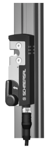
AZM40适合安装在40 mm型材上,并且由于操动件具有180°的角度灵活性,它也适用于旋转门和滑动门。LED灯是三侧可视的。
- 安全开关根据EN ISO 14119分类为4型联锁设备。带有单独编码的设计被分为高度编码。
不同的型号可以作为带有联锁功能或是电磁安全锁的安全开关。
- 如果风险分析表明使用了受监控的联锁,则应使用带受监控联锁的型号,并在订货代码中标记为>符号
操动件监控器(B)是带有对过程保护起联锁功能的安全开关。
本产品的安全功能在于,在防护门解锁或打开的过程中确保关闭安全输出,并在防护门打开的状态下始终确保安全输出保持关闭状态。
AZM40电磁安全锁是双稳态系统,即在电源故障的情况下,锁将维持在断电时的位置。
串联接线
可串联连接。在串联的情况下,风险时间保持不变,反应时间按技术数据中规定的每增加一个单位的输入的反应时间的总和增加。根据技术数据,设备数量仅受电缆掉落和外部电缆熔断保护的限制。
- 用户在评估和设计安全链时,必须根据相关标准和和规定,并满足所要求的安全等级。如果同一个安全功能当中包含多个安全开关,必须将单个组件的PFH值相加。
- 集成了安全部件在内的完整控制系统设计必须符合相关标准。
2.4 技术参数
总体数据
| 标准型 |
EN ISO 13849-1 EN ISO 14119 EN IEC 60947-5-3 EN IEC 61508 |
| 编码 |
通用编码 |
| 编码等级,依据EN ISO 14119 |
低 |
| 工作原理 |
RFID |
| 频段 RFID |
125 kHz |
| 发射器输出 RFID, 最大植 |
-6 dB/m |
| 外壳材料 |
轻合金压铸件和塑料 (玻璃纤维增强热塑塑料,自熄灭) |
| 响应时间,最大 |
100 ms |
| 风险持续期,最大 |
200 ms |
| 响应时间,通过安全输入关闭安全输出,最大值 |
1.5 ms |
| 毛重 |
300 g |
总体数据 - 产品特性
| 电磁安全锁,受监控 |
是 |
| 锁 |
是 |
| 手动解锁 |
是 |
| 短路检测 |
是 |
| 交叉电路检测 |
是 |
| 串联连接 |
是 |
| 安全功能 |
是 |
| 整个系统检测,状态 |
是 |
| 安全触点数量 |
2 |
安全评估
| 标准型 |
EN ISO 13849-1 EN IEC 61508 |
安全评估 - 联锁
| 性能水平,最高 |
e |
| 类别 |
4 |
| PFH值 |
1.10 x 10⁻⁹ /h |
| PFD值 |
8.90 x 10⁻⁵ |
| 安全完整性等级 (SIL),停止 0,适用于以下应用 |
3 |
| 任务时间 |
20 年 |
安全评估 - 防护锁定
| 性能水平,最高 |
d |
| 类别 |
2 |
| PFH值 |
3.00 x 10⁻⁹ /h |
| PFD值 |
2.40 x 10⁻⁴ |
| 安全完整性等级 (SIL),停止 0,适用于以下应用 |
2 |
| 任务时间 |
20 年 |
机械参数
| 联锁原理 |
双稳定 |
| 机械寿命, 锁定周期 |
1,000,000 操作 |
| 机械寿命, 操动件循环 |
200,000 操作 |
| 保持力 FZh 按照 EN ISO 14119 |
2,000 N |
| 锁紧力 Fmax, 最大 |
2,600 N |
| 锁定力 |
40 N |
| 注,(闩锁力) |
+/- 25% |
| 操动速度,最大 |
0.5 m/s |
| 安装 |
安装孔 埋头孔 |
| 固定螺丝类型 |
2x M5 |
| 固定螺钉的紧锢力矩, 最低限度 |
4 Nm |
Mechanical data - Switching distances
| 肯定开关距离 "ON" Sao |
1 mm |
| 肯定闭合距离 "OFF" Sar |
8 mm |
| 注意(开关距离) |
All switching distances in accordance EN IEC 60947-5-3 |
机械参数 - 连接技术
| 传感器链长度,最大 |
30 m |
| 注意 (传感器链长度) |
根据输出电流,电缆长度和电缆截面会改变电压降 |
| 注意 (串联连接) |
设备数量不限,oberserve 外部线路熔断,最多可连接 31 台设备。在串行诊断 SD 的情况下,最多可连接 31 台设备 |
| 连接器 |
连接器M12,8芯,A编码 |
机械参数 - 尺寸
| 传感器长度 |
119.5 mm |
| 传感器宽度 |
40 mm |
| 传感器高度 |
20 mm |
环境条件
| 防护等级 |
IP66 IP67 |
| 工作环境温度 |
+0 ... +55 °C |
| 储存和运输温度 |
-40 ... +85 °C |
| 最大相对湿度 |
93 % |
| 注(相对湿度) |
无冷凝 不结冰 |
| 抗振动 |
10 ... 55 Hz,振幅 1 mm |
| 耐冲击 |
30 g / 11 ms |
| 防护等级 |
III |
| 最大允许安装海拔高度 |
2,000 m |
环境条件 - 绝缘值
| 额定绝缘电压 Ui |
32 VDC |
| 额定冲击耐受电压 Uimp |
0.8 kV |
| 过电压级别 |
III |
| 污染等级 |
3 |
电气参数
| 工作电压 |
24 VDC -15 % / +10 % (稳定PELV电源) |
| 空载电源电流 I0, 典型 |
100 mA |
| 开关瞬间的电流消耗磁铁,峰值 |
600 mA / 100 ms |
| 额定工作电压 |
24 VDC |
| 工作电流 |
1,200 mA |
| 要求额定短路电流 |
100 A |
| 外部电线和设备保险丝额定值 |
2 A gG |
| 准备就绪时间,最大 |
4,000 ms |
| 转换频率,最大 |
0.25 Hz |
| 应用类别 DC-12 |
24 VDC / 0.05 A |
| 电气保险丝容量,最大 |
2 A |
电气参数 - 线圈控制
| 指定, 线圈控制 |
IN |
| 开关阈值 |
-3 V … 5 V (Low) 15 V … 30 V (High) |
| 磁铁闭合时间 |
100 % |
| 测试脉冲持续时间, 最大 |
5 ms |
| 测试脉冲间隔, 最低限度 |
40 ms |
| 分类 ZVEI CB24I,接收器 |
C0 |
| 分类 ZVEI CB24I,信号源 |
C1 C2 C3 |
| 24V时,电流消耗,最小 |
10 mA |
| 24V时,电流消耗,最大 |
15 mA |
电子参数 - 安全数字输入
| 指定,安全输入 |
X1 和 X2 |
| 开关阈值 |
−3 V … 5 V (Low) 15 V … 30 V (High) |
| 24V时,电流消耗 |
5 mA |
| 测试脉冲持续时间, 最大 |
1 ms |
| 测试脉冲间隔, 最低限度 |
100 ms |
| 分类 ZVEI CB24I,接收器 |
C1 |
| 分类 ZVEI CB24I,信号源 |
C1 C2 C3 |
电气参数 - 安全数字输出
| 指定,安全输出 |
Y1和Y2 |
| 额定工作电流(安全输出) |
250 mA |
| 控制元件的设计 |
短路保护,P型 |
| 电压降 Ud, 最大电压降 Ud, 最大 |
2 V |
| 泄漏电流 Ir, 最大植 |
0.5 mA |
| 电压,应用类别 DC-12 |
24 VDC |
| 电流,应用类别 DC-12 |
0.25 A |
| 电压,应用类别 DC-13 |
24 VDC |
| 电流,应用类别 DC-13 |
0.25 A |
| 测试脉冲间隔,典型 |
1000 ms |
| 测试脉冲持续时间, 最大 |
0.5 ms |
| 分类 ZVEI CB24I,信号源 |
C2 |
| 分类 ZVEI CB24I,接收器 |
C1 C2 |
电气参数 - 诊断输出
| 指定, 诊断输出 |
OUT |
| 控制元件的设计 |
短路保护,P型 |
| 电压降 Ud, 最大电压降 Ud, 最大 |
2 V |
| 电压,应用类别 DC-12 |
24 VDC |
| 电流,应用类别 DC-12 |
0.05 A |
| 电压,应用类别 DC-13 |
24 VDC |
| 电流,应用类别 DC-13 |
0.05 A |
状态显示
| 注 (LED开关状态显示) |
工作状态:LED绿色 错误 / 功能故障:LED红色 供电电压 UB:LED 绿色 |
引脚分配
| PIN 1 |
A1 电源电压 UB |
| PIN 2 |
X1 安全输入 1 |
| PIN 3 |
A2 GND |
| PIN 4 |
Y1 安全输出 1 |
| PIN 5 |
OUT 监控输出 |
| PIN 6 |
X2 安全输入 2 |
| PIN 7 |
Y2 安全输出 2 |
| PIN 8 |
IN 线圈控制 |
安全分类注意事项
- 防护锁定功能的安全分类仅适用于带受监控电磁安全锁AZM40Z...1P2P-… 的标准设备(见订货代码)。
- 联锁的操动必须与OSSD释放器进行外部比较。如果是由于非故意解锁而导致的停机,则会通过外部诊断检测到。
- 防护锁定功能的安全分析是指将电磁安全锁AZM作为整个系统的一部分。
客户方必须执行进一步措施以避免发生故障,例如安全操动和安全地连接电缆。
如果出现某一故障导致锁定功能解锁,电磁安全锁将会探测到这一情况,防护门Y1/Y2将会安全关闭。当这种故障发生时,在机器达到安全状态之前,保护设备可能会立即打开,仅有一次。类别2所定义的系统反应允许在检测之间发生故障,并导致安全功能丧失,而安全功能丧失的情况则由检测功能探测识别出来。
FCC/IC - 注意
本设备符合FCC规则第15部分,并包含符合ISED(创新、科学和经济发展)加拿大免许可RSS标准的免许可发射器/接收器。
操作须满足以下两个条件:
(1) 该设备不得产生有害的干扰信号;
(2) 该设备必须能够承受干扰信号。其中还包括可能导致设备无法正常工作的干扰信号。
该设备在最小距离为100 mm时符合神经刺激限制 (ISED SPR-002)。未经K.A. Schmersal GmbH & Co. KG明确批准的更改或修改 可能会导致用户使用该设备的授权失效。
该设备中包含的免许可发射器/接收器满足加拿大创新、科学和经济发展(ISED)机构适用于免许可无线电设备的“无线电标准规范”的要求。在下列两种情况下允许操作:
(1) 该设备不得产生干扰。
(2) 设备必须能够承受接收到的射频干扰,即使这可能会损害其功能。
该设备在最小距离为 100 mm时符合神经刺激限制 (ISED CNR-102)。
如果未经K.A.Schmersal GmbH & Co. KG明确批准进行的更改或修改 可能会导致用户使用该设备的授权失效。
| 20941-22-14519 | Este equipamento nao tem direito àprotecao contra interferência prejudicial e nao pode causar interferencia em sistemas devidamente autorizados. Para maiores informacores consultar: www.gov.br/anatel |
3 安装
3.1 安装概述
- 请遵守EN ISO 12100、EN ISO 14119和EN ISO 14120标准中的有关规定。
任何职位都有可能。
严禁将电磁安全锁用作限位挡块。
必须取下运输锁。

为了连接电磁安全锁和操动件,提供了两个用于 M5 螺钉的安装孔。
- M5螺钉的强度至少要达到8.8级,不锈钢则要达到80级。M5螺栓的拧紧扭矩为4至6Nm,最大拧紧扭矩取决于所使用的紧固螺钉。
- 电磁安全锁已锁定 已锁螺栓上和操动件凹槽内的润滑脂不得去除。
- 必须避免在锚杆区堆积细粒污垢。在这种情况下,螺栓从下向上的安装方式并不可取。
操动件的安装必须避免受到外部影响而损坏。
- 只有在干冷的情况下才允许在冰点以下的温度下使用。客户在组装安全开关时必须考虑到这一点。
- 带锁紧螺栓的电磁锁(A)和带有三角形标记的操动件(B)必须以相同的安装方向安装。

执行方向
操动件可连续插入至180°。

- 操动件必须永久固定在安全防护门上,通过合适的措施防止移位(防破坏螺栓、胶接、螺栓头钻孔等)。
授权操动件和联锁偏移
| 倾斜角度 | 旋转角度 |
|---|---|
 |  |
| 操动方向和开关距离 | ||
|---|---|---|
| AZM40操作时可有如下容差限制: | ||
| X轴 | - 3 mm |  |
| Y轴 | ±1 mm | |
| Z轴 | ± 1.5 mm (操动件在中心位置) | |
调整
通过使用2 mm六角扳手AF,2颗内六角螺钉M4可用于向X方向调整操动件舌片。
通过 M4Local 内六角螺钉进行调节

- 切勿完全拧开内六角螺钉。
为防止因系统条件造成的影响并缩短开关距离,请遵守以下要求:
- 电磁安全锁和操动件的区域中的金属件及磁场会影响开关距离或导致故障。
- 远离金属碎屑。
AZM40电磁安全锁之间的最小距离(mm)

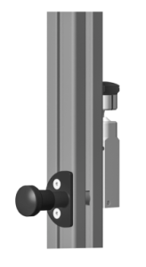
3.2 手动解锁
为便于安装和维护,电磁联锁可在断电状态下解锁。通过逆时针转动辅助解锁装置可解锁电磁安全锁。仅在手动解锁已恢复到其初始位置P后,才恢复正常的锁定功能。
- 手动解锁不得过度旋转超过止端。
操作手动解锁装置需要工具(建议:0.8 x 4 至 4.5 mm的一字螺丝刀)。
手动解锁装置必须防止意外启动,例如完成调试后使用随附的密封件。
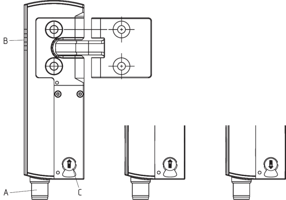
| 注释 | |
|---|---|
| A | 连接插头M12,8针 |
| B | LED显示 |
| C | 手动解锁(两边) |
 | 电磁安全锁准备就绪 |
 | 电磁安全锁未准备就绪 |
3.3 尺寸
测量值均以mm为单位。

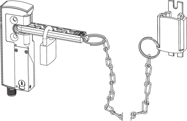
改装套件紧急出口/紧急释放装置
改装套件用于随后对电磁安全锁进行功能扩展。
| 名称 | 订货代码 | |
|---|---|---|
| 紧急逃逸 | ACC-AZM40-LEV-T | 103054265 |
| 紧急解锁 | ACC-AZM40-LEV-N | 103054268 |
| 带按钮的 紧急出口 - for 40 mm profiles - 用于最大 170 mm的型材 | ACC-AZM40-PT-T-40MM ACC-AZM40-PT-T-170MM | 103054271 103054273 |
| 用于 40 mm型材的带 按钮 紧急释放装置 - 用于最大 170 mm的型材 | ACC-AZM40-PT-N-40MM ACC-AZM40-PT-N-170MM | 103054275 103054277 |
| ACC-AZM40-LEV | ACC-AZM40-PT |
|---|---|
 |  |
| 名称 | 订货代码 | |
|---|---|---|
| 锁定装置 | SZ40 | 103053182 |
| 通用安装板,适用于20、30、45、50和60 mm型材系统,2件。 | MP-AZM40 | 103045324 |
| 防拆螺钉 M5 x 25,平头,2件。 | ACC-NRS-M5X25-FHS-2PCS | 103045415 |
| 防拆螺钉 M5 x 25,平头,2件。 | ACC-NRS-M5X25-CSS-2PCS | 103045416 |
| SZ40 | MP-AZM40 |
|---|---|
 |  |
4 电气连接
4.1 电气接线指示
- 电气接线需在电源关闭的情况下由授权专业人员完成。
电压输入A1、X1、X2和IN必须配备抗持续过压保护。推荐使用符合标准EN 60204-1的电源。
所需的电缆保险丝保护必须集成在安装中。
安全输出可直接接入控制系统的安全电路。
4.2 连接安全监控模块的要求
双通道安全输入,适于2个p-型半导体输出 (OSSD)
- 安全控制器配置
如果安全开关设备连接到电子安全监控模块,我们建议您设置至少100 ms的差异时间。安全监控模块的安全输入必须能够消隐大约1 ms的测试脉冲。安全监控模块不需要具有交叉短路监控功能,如有必要,必须关闭交叉短路监控。
- 有关选择合适安全监控模块的技术信息,请查阅施迈赛产品目录或访问以下网址,查阅在线目录:products.schmersal.com
4.3 接线配置和连接器配件
| 安全开关功能 | 连接器线脚配置 | 施迈赛插头导体 编号的颜色代码 | Poss. 符合EN 60947-5-2的商用 连接插头 的其他可能的颜色代码 | |||
|---|---|---|---|---|---|---|
| 带常规诊断输出 |  | P67 / IP69 acc. DIN 47100 标准 | IP69 (PVC) | |||
| A1 | Ue | 1 | WH | BN | BN | |
| X1 | 安全输入1 | 2 | BN | WH | WH | |
| A2 | GND | 3 | GN | BU | BU | |
| Y1 | 安全输出1 | 4 | YE | BK | BK | |
| OUT | 诊断输出 | 5 | GY | GY | GY | |
| X2 | 安全输入2 | 6 | PK | VT | PK | |
| Y2 | 安全输出2 | 7 | BU | RD | VT | |
| IN | 磁力控制 | 8 | RD | PK | OR | |
附件 带线
| 带插口的预接线电缆(母) M12, 8针 - 8 x 0.25 mm², IP67 / IP69 | |
|---|---|
| 电缆长度 | 订货代码 |
| 2.5 m | 103011415 |
| 5.0 m | 103007358 |
| 10.0 m | 103007359 |
| 15.0 m | 103011414 |
| 连接电缆(PVC)带耦合器(母) M12, 8针 - 8 x 0.21 mm², IP69 | |
|---|---|
| 电缆长度 | 订货代码 |
| 5.0 m | 101210560 |
| 5.0m,成角度的 | 101210561 |
| 10.0 m | 103001389 |
| 15.0 m | 103014823 |
其他长度的版本和有角度的电缆出口可以根据要求提供。
- 在使用有角度的连接器时,它应与连接表面平行并指向背离操动件的一侧。
4.4 接线图示
图中所示应用仅为示例。并不能解除用户事先仔细审查开关及其设置是否符合具体应用要求的责任。图中所示应用仅为示例。
接线示例: 串联接线 AZM40
在连锁终端安全部件的两个安全输入端上都有电压(从安全监控模块考虑)。第一个安全组件的安全输出与安全监控模块相连。

Y1和Y2 = 安全输出 → 安全监控模块
5 操动件教学 / 操动件监测
采用标准编码的电磁安全锁到货即可使用。
单独编码的电磁安全锁以及操动件需要进行以下示教步骤:
- 关闭电磁锁的电源并重新接通.
- 将操动件置于探测范围内。电磁安全锁将显示示教正在进行中,红色LED亮起,黄色LED闪烁(1 Hz)。
- 10秒过后,快速闪动黄色信号(3 Hz)提示断开电磁锁的有效电压。(如果电压在5分钟内未断开,电磁安全锁将中断示教步骤并闪烁5次红灯,表示操动件错误)。
- 一旦工作电压重新接通,必须再次检测操动件,以激活已示教的操动件代码。这一操作将确定保存已激活的编码!
对于订购后缀为-I1的设备,安全开关设备和操动件的执行分配是不可逆的。
对于订货后缀为-I2的设备,可无限次地重新示教新的操动件。示教新操动件时,此前的编码将作废。随后,将启动一个为时10分钟的放行阻止程序,此间防止更改的保护性能将提高。放行阻止程序结束时,绿色LED将会闪烁亮起,表明探测到了新操动件。如果在10分钟的放行阻止期间发生断电,则该程序会重新启动。
6 主动原理和诊断功能
6.1 磁力控制
双稳态联锁通过输入信号 (= 24 V) 的操作设置解除。如果未设置输入信号(= 0 V),则电磁安全锁进入锁定状态,前提是将正确的操动件插入电磁安全锁中。
6.2 安全输出的工作方式
对于标准规格的AZM 40Z,电磁安全锁解锁会导致安全输出断开。若操动件保持插入在AZM40Z电磁安全锁当中,已解锁的防护门会重新锁定。在这种情况下,安全输出会重新接通。
安全防护装置不得打开。
对于AZM300B,开启防护门会导致安全输出断开。
如果安全输出已经启用,任何不会立即影响电磁安全锁功能的错误(例如,环境温度过高,安全输出端的干扰电位,交叉线短路)都会导致警告信息,诊断输出断开和安全输出的滞后关闭。如果警告信息处于激活状态超过30分钟,安全输出将被断开。使用诊断输出断开但安全通道仍闭合这一信号组合可将机器在受控状态下停机。故障排除后,可通过开启相应的防护门复位故障消息。
6.3 诊断LED
电磁安全锁通过3色LED显示工作状况及出错。
| 绿色(电源) | 供电电压接通 |
| 黄色(状态) | 工作状态 |
| 红色(故障) | 错误(见表 2: 错误信息 / 红色诊断LED的指示灯编码 |
绿色LED表示工作准备就绪。电源接通,有所有安全输入。绿色LED闪烁(1Hz)表示一个或两个安全输入(X1 和/或 X2)的电压缺失。
| 系统状况 X1和/或X2无输入信号 | LED | ||
|---|---|---|---|
| 绿色 | 红色 | 黄色 | |
| 安全防护门打开,且安全电路上游的安全门也打开 | 闪烁 (1 Hz) | 关 | 关 |
| 安全防护门关闭,且安全电路上游的安全防护门也打开 | 闪烁 (1 Hz) | 关 | 闪烁 |
| 安全防护门锁定,且安全电路上游的安全防护门打开 | 闪烁 (1 Hz) | 关 | 开 |
6.4 诊断输出
抗短路诊断输出OUT可用于中央显示,或者用于非安全控制功能当中,例如PLC。
诊断输出是非安全相关的输出。
错误警告
已经发生故障,导致安全输出在30分钟后停用(LED“故障”闪烁,见表2)。安全输出初始保持使能状态(最大30分钟)。这样,可以在受控状态下完成关机。当错误原因排除后,错误警告则被删除。
错误
不再保证电磁安全锁安全功能的错误(内部错误)会导致安全输出立即禁用。不会立即影响电磁安全锁的错误(例如环境温度过高、安全输出处有干扰电势、短路)会导致延迟关闭(参见表2)。故障排除后,可通过开启相应的防护门复位故障消息。
- 电磁安全锁的强制开启由所有LED同步闪烁表示。然后必须更换电磁锁和操动件。
- 如果在安全输出中检测到不止一个故障或在Y1和Y2之间检测到交叉电路,则自动进行电子锁定。这意味着,常规的错误将无法确认。要复位此类联锁,必须在消除错误原因后将电磁安全锁与电源电压切断。
以执行器监控的防护装置锁定为例,诊断输出的行为
顺序,门关闭后发出闭锁信号

顺序,在门关闭前发出锁定信号

进程中断,门无法锁定或错误


 | 锁定 |  | 解锁 |  | 上锁时间 |
 | 防护门打开 |  | 防护门关闭 | ||
 | 防护门未锁止或故障 |  | 防护门锁止 |
6.5 诊断信息
| 表 1:安全开关的诊断信息 | |||||||
|---|---|---|---|---|---|---|---|
| 系统环境 | 磁力控制 (双稳态) IN | LED | 安全输出 Y1, Y2 | 诊断输出 OUT | |||
| 绿色 | 红色 | 黄色 | AZM40Z | AZM40B | |||
| 防护门打开 | 24 V | 开 | 关 | 关 | 0 V | 0 V | 0 V |
| 防护门关闭, 未锁止 | 24 V | 开 | 关 | 闪烁 | 0 V | 24 V | 24 V |
| 防护门关闭,无法上锁 | 0 V | 开 | 闪烁 2) | 闪烁 | 0 V | 24 V | 0 V |
| 防护门关闭并上锁 | 0 V | 开 | 关 | 开 | 24 V | 24 V | 24 V |
| 错误警告 1) | 0 V / 24 V | 开 | 闪烁 2) | 闪烁 | 24 V / 0 V | 24 V1) | 0 V |
| 错误 | 0 V / 24 V | 闪烁 2) | 0 V | 0 V | 0 V | ||
| 机械过载故障3) | 0 V | 闪烁同步 | 闪烁同步 | 闪烁同步 | 0 V | 0 V | 0 V |
| 输入电路X1和/或X2出错 | 0 V / 24 V | 闪烁 | 关 | S. 诊断LEDs 部分 | 取决于系统状态 | ||
| 预警级别 使用寿命(95% 使用寿命) | 0 V / 24 V | 闪烁同步 | 闪烁同步 | 开 / 闪烁 / 关闭 | 取决于系统状态 | ||
| 达到最大使用寿命 | 0 V / 24 V | 闪烁交替 | 闪烁交替 | 关 | 0 V | 0 V | 0 V |
| 额外对于I1和I2型: | |||||||
| 示教过程操动件启动 | 24 V | 关 | 开 | 闪烁 | 0 V | 0 V | 0 V |
| 仅I2:示教过程操动件 (释放块) | 24 V | 闪烁 | 关 | 关 | 0 V | 0 V | 0 V |
| 1) 30分钟后:由于错误而关闭 2) 秒 闪存代码 3)如果出现与机械过载故障有关的投诉,则必须将包括相关操动件在内的设备送回。 | |||||||
| 表2:错误信息/红色诊断LED的闪烁编码 | |||
|---|---|---|---|
| 指示灯闪烁编码(红色) | 名称 | 自行关闭 等候时间 | 错误原因 |
| 1次闪烁 | 错误(警告)位于输出Y1 | 30分钟 | 输出测试错误或输出Y1断开后仍存在电压。 |
| 2次闪烁 | 错误(警告)位于输出Y2 | 30分钟 | 输出测试错误或输出Y2断开后仍存在电压。 |
| 3次闪烁 | 错误(警告)交叉短路 | 30分钟 | 输出电缆交叉短路或两个输出端口故障 |
| 4次闪烁 | 错误(警告)温度过高 | 30分钟 | 温度测量显示内部温度过高 |
| 5次闪烁 | 操动件故障 | 0分钟 | 操动件错误或故障 |
| 6次闪烁 | 内部错误 | 0分钟 | 控制输入错误 |
| 7次闪烁 | 错误,联锁操动件 | 0分钟 | 手动解锁装置的锁定/解锁受阻/位置不正确(至少在两侧) |
| 8次闪烁 | 错误(警告)过压/欠压 | 30分钟 | 电源电压超出规范 |
| 红色持续亮起 | 内部错误 | 0分钟 | 设备故障 |
7 调试与维护
7.1 功能检查
该安全开关的安全功能必须进行检查。 事先要检查并满足下列条件:
- 安装并确保电缆连接完好无损。
- 检查开关外壳是否损坏
- 去除污垢。
7.2 维护
在正确安装和预期用途的情况下,安全开关设备是免维护的。
推荐按照下列内容进行常规的目测检查和功能测试:
- 检查操动件和电磁安全锁是否可靠安装。
- 检查最大。传动装置和电磁锁的最大偏差以及最大倾角和旋转角,必要时使用M4套筒头螺钉进行调整。
- 安装并确保电缆连接完好无损。
- 检查开关外壳和执行机构是否损坏。
- 去除污垢。
- 必须采取相应措施以防止发生蓄意破坏或回避安全防护装置的行为,例如可使用替代操动件。
- 损坏或故障部件必须更换。
- 在达到 1,000,000 次锁闭循环或 500,000 次执行机构循环的使用寿命后(“V2 ”型,见铭牌),电磁锁不再能锁闭,必须连同执行机构一起更换。
8 拆卸与处理
8.1 拆卸
该开关必须在电源关闭的情况下进行拆卸。
8.2 处理
- 该开关必须按照相关的国家标准和法规进行处理。
施迈赛工业开关制造(上海)有限公司, 上海市青浦区漕盈路3336号,
所涉及的详细信息和数据已经过仔细检查。 图像可能与原始图像有所不同。 您可在说明书中进一步获得技术数据。 可能会有技术修改和错误。
生成日期 2025/6/15 下午11:17