AZM400Z-ST-I2-1P2P
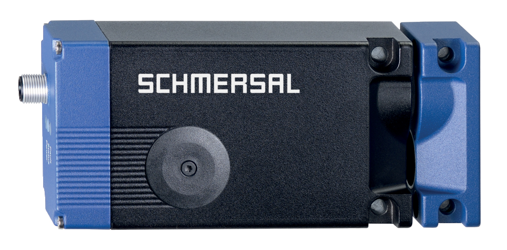
AZM400Z-ST-I2-1P2P
| Descrição do tipo de produtos: AZM400Z-(1)-(2)-(3)-(4)-(5) |
| (1) | |
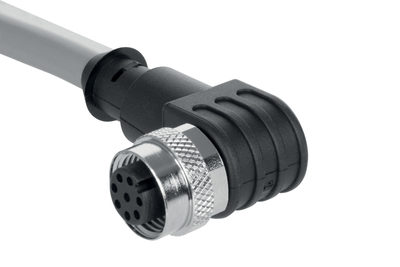
| ST | 1 Conector M12 incorporado, 8 polos |
| ST2 | 2 conectores M12 incorporados, 8 pinos / 5 pinos |
| (2) | |
| sem | Codificação Standard |
| I1 | Codificação individual |
| I2 | Codificação individual, aprendizagem múltipla |
| (3) | |
| 1P2P | 1 saída para diagnóstico e 2 saídas de segurança, comutação p (Só para ST) |
| 2P2P | 2 saídas para diagnóstico e 2 saídas de segurança, comutação p (só para ST2) |
| (4) | |
| sem | Desbloqueio auxiliar |
| T | Dispositivo de destravamento de emergência (anti-pânico) |
| BOW | Com furos de montagem para a montagem com cabo Bowden |
| (5) | |
| sem | Sem desbloqueio eletrônico auxiliar (só para ST) |
| E | Com desbloqueio eletrónico auxiliar (só para St2) |
- Codificação individual programável repetidamente com tecnologia RFID
- Nível de codificação ELEVADO de acordo com ISO 14119
- Conector M12, 8 polos
- Supervisão de fechamento
- 1 Saída para diagnóstico
- rearme manual
- Sistema biestável, acionado por motor
- Força de engate 10.000 N
- Possibilidade de destravamento contra uma força transversal de até 300 N
- PL e / cat. 4 / SIL 3 para função de travamento e retenção de segurança
- Comando de dois canais da função de retenção
- Funcionamento em saídas de comutação P/P e P/N
- Elevada tolerância do atuador
Código para encomenda
| Código ACE Schmersal |
11930326 |
| Descrição do tipo de produtos |
AZM400Z-ST-I2-1P2P |
| Número de artigo (Número de encomenda) |
103003733 |
| EAN (European Article Number) |
4030661472614 |
| Número eCl@ss, versão 12.0 |
27-27-26-03 |
| Número eCl@ss, versão 11.0 |
27-27-26-03 |
| Número eCl@ss, versão 9.0 |
27-27-26-03 |
| Número ETIM, versão 7.0 |
EC002593 |
| Número ETIM, versão 6.0 |
EC002593 |
Homologações - Instruções
|
TÜV cULus FCC IC ANATEL |
Propriedades globais
| Instruções |
EN ISO 13849-1 EN ISO 14119 EN IEC 60947-5-3 EN IEC 61508 |
| informações gerais |
Codificação individual, aprendizagem múltipla |
| Nível de codificação conforme EN ISO 14119 |
Alto |
| Princípio ativo |
Campo magnético RFID |
| Banda de frequência RFID |
125 kHz |
| Potência de envio RFID, máximo |
-6 dBm |
| Material do invólucro |
Metal leve fundido sob pressão |
| Tempo de reação do atuador, máximo |
100 ms |
| Peso bruto |
764 g |
Propriedades globais - Características
| Supervisão de fechamento |
Sim |
| Desbloqueio auxiliar |
Sim |
| Detecção de curto-circuito |
Sim |
| Reconhecimento de curto-circuitos |
Sim |
| Funções de segurança |
Sim |
| Indicação integrada, estado |
Sim |
| Quantidade de sinais de diagnóstico |
1 |
| Número de contatos de segurança |
2 |
Classificação
| Normas, regulamentos |
EN ISO 13849-1 EN IEC 61508 |
Classificação - função de solenoide adicional
| Performance Level, até |
e |
| Categoria de comando |
4 |
| Valor PFH |
1,00 x 10⁻⁹ /h |
| Valor PFD |
9,00 x 10⁻⁵ |
| Safety Integrity Level (SIL), apropriado na |
3 |
| Vida útil |
20 Ano(s) |
Classificação - função de bloqueio
| Performance Level, até |
e |
| Categoria de comando |
4 |
| Valor PFH |
1,80 x 10⁻⁹ /h |
| Valor PFD |
1,60 x 10⁻⁴ |
| Safety Integrity Level (SIL), apropriado na |
3 |
| Vida útil |
20 Ano(s) |
Dados mecânicos
| Princípio de travamento |
biestável |
| Mínima resistência mecânica |
1.000.000 comutações |
| Orientação (resistência mecânica) |
Dos quais, com força transversal Ftransv = 100 N:100.000 ciclos de comutação |
| Distância admissível do bloqueio ao atuador, mínimo |
1 mm |
| Distância admissível do bloqueio ao atuador, máximo |
7 mm |
| Desalinhamento angular entre solenoide e atuador, máximo |
2 ° |
| Distância mínima entre dispositivos |
30 mm |
| Força de engate segundo a EN ISO 14119 |
10.000 N |
| Força de engate, máximo |
13.000 N |
| Força transversal no retorno do pino, máxima (contra porta tensionada) |
300 N |
| Orientação (força transversal máxima no retorno do pino) |
Não aplicável para desbloqueio-, Cabo Bowden- e desbloqueio auxiliar |
| Versão dos parafusos de fixação |
2x M6 |
| Nota (versão dos parafusos de fixação) |
Classe de resistência mín. 10.9 |
| Binário de aperto do parafuso |
8 Nm |
| Orientação |
O binário de aperto máximo do parafuso da tampa (tampa triangular) é de 0,55 Nm. |
Dados mecânicos - dimensões
| Conexão, conector |
Conector M12, 8 polos, codificação-A |
Dados mecânicos - dimensões
| Comprimento do sensor |
46,7 mm |
| Largura de sensor |
77,8 mm |
| Altura do sensor |
156,7 mm |
Ambiente
| Tipo de proteção |
IP66 IP67 |
| Temperatura ambiente |
-20 ... +55 °C |
| Temperatura para armazenar e transportar |
-40 ... +85 °C |
| Máxima umidade relativa |
93 % |
| Orientação (humidade relativa) |
não condensado sem gelo |
| Resistência a vibrações conforme EN 60068-2-6: |
10 … 150 Hz, amplitude 0.35 mm |
| Resistência a impactos |
30 g / 11 ms |
| Classe de proteção |
III |
| Altura de instalação permitida sobre NN, máximo |
2.000 m |
Ambiente - Parâmetros de isolamento
| Medição de isolação da tensão |
32 VDC |
| Medição da rigidez dielétrica da tensão máxima |
0,8 kV |
| Categoria de sobre-tensão |
III |
| Grau de contaminação por sujeira conf. VDE 0100 |
3 |
Dados elétricos
| Tensão de operação |
24 VDC -15 % / +10 % (fonte de alimentação PELV) |
| Corrente de circuito aberto I0, típico |
100 mA |
| Consumo de corrente durante o movimento do perno, valor de pico |
600 mA / 100 ms |
| Medição da tensão de operação |
24 VDC |
| Corrente de curto-circuito de acordo com EN 60947-5-1 {A} |
100 A |
| Isolação externa de cabos e equipamento |
2A gG |
| Atraso na operação, máximo |
1.500 ms |
| Frequência de comutação, máximo |
0,3 Hz |
| Ciclo de fecho/abertura, mínimo |
3 s |
| Tempo de ciclo médio mínimo (com operação contínua) |
20 s |
| Categoria de aplicação DC-12 |
24 VDC / 0,05 A |
| Dados elétricos, máximo |
2 A |
Dados elétricos – Entradas de comando
| Designação, entradas de comando |
E1 e E2 (comutação p), E3 (comutação n) |
| Limiares de comutação das entradas de comando |
−3 V … 5 V (Low) 15 V … 30 V (High) |
| Classificação ZVEI CB24I, descida |
C0 |
| Classificação ZVEI CB24I, fonte |
C1 C2 C3 |
| Consumo de corrente a 24 V, mínimo |
5 mA |
| Consumo de corrente a 24 V, máximo |
10 mA |
| Tempo de discrepância admissível do sinal de entrada, máximo |
10 s |
| Intervalo do impulso de teste, máximo |
40 ms |
| Duração do impulso de teste, máximo |
5 ms |
| Corrente residual admissível do comando |
1,5 mA |
Dados elétricos - Saída de segurança
| Designação, saídas de segurança |
Y1 e Y2 |
| Versão |
À prova de curto-circuito, tipo p |
| Queda de tensão Ud, máximo |
2 V |
| Corrente residual |
0,5 mA |
| Tensão, categoria de aplicação DC-12 |
24 VDC |
| Potência, categoria de aplicação DC-12 |
0,25 A |
| Tensão, categoria de aplicação DC-13 |
24 VDC |
| Potência, categoria de aplicação DC-13 |
0,25 A |
| Intervalo do impulso de teste, típico |
1000 ms |
| Duração do impulso de teste, máximo |
0,5 ms |
| Classificação ZVEI CB24I, fonte |
C2 |
| Classificação ZVEI CB24I, descida |
C1 C2 |
Dados elétricos - saída diagnóstico
| Designação, saídas de diagnóstico |
OUT |
| Versão |
À prova de curto-circuito, tipo p |
| Orientação |
As saídas de diagnóstico não são saídas relevantes para a segurança! |
| Queda de tensão Ud, máximo |
2 V |
| Tensão, categoria de aplicação DC-12 |
24 VDC |
| Potência, categoria de aplicação DC-12 |
0,05 A |
| Tensão, categoria de aplicação DC-13 |
24 VDC |
| Potência, categoria de aplicação DC-13 |
0,05 A |
Indicação de Estado
| Orientação (LED indicador do estado) |
Estado operacional : LED amarelo Falha avaria funcional: LED vermelho Tensão de alimentação UB: LED verde indica |
Descrição dos pinos
| PIN 1 |
A1 Tensão de alimentação UB |
| PIN 2 |
E1 1 |
| PIN 3 |
A2 GND |
| PIN 4 |
Y1 Saída de segurança 1 |
| PIN 5 |
OUT Saída de diagnóstico |
| PIN 6 |
E3 3 |
| PIN 7 |
Y2 Saída de segurança 2 |
| PIN 8 |
E2 2 |
Escopo do fornecimento
| Escopo do fornecimento |
O atuador não está incluído no fornecimento. |
Acessórios
| Recomendação (Atuador) |
AZM400-B1 |
Filtro de idioma
Ficha técnica
Manual de instruções e Declaração de conformidade
Certificação TÜV
Certificação UL
ANATEL certification
Folheto
SISTEMA-VDMA Biblioteca/Library
Faça download da versão mais recente do Adobe Reader
Foto do produto (foto individual do catálogo )
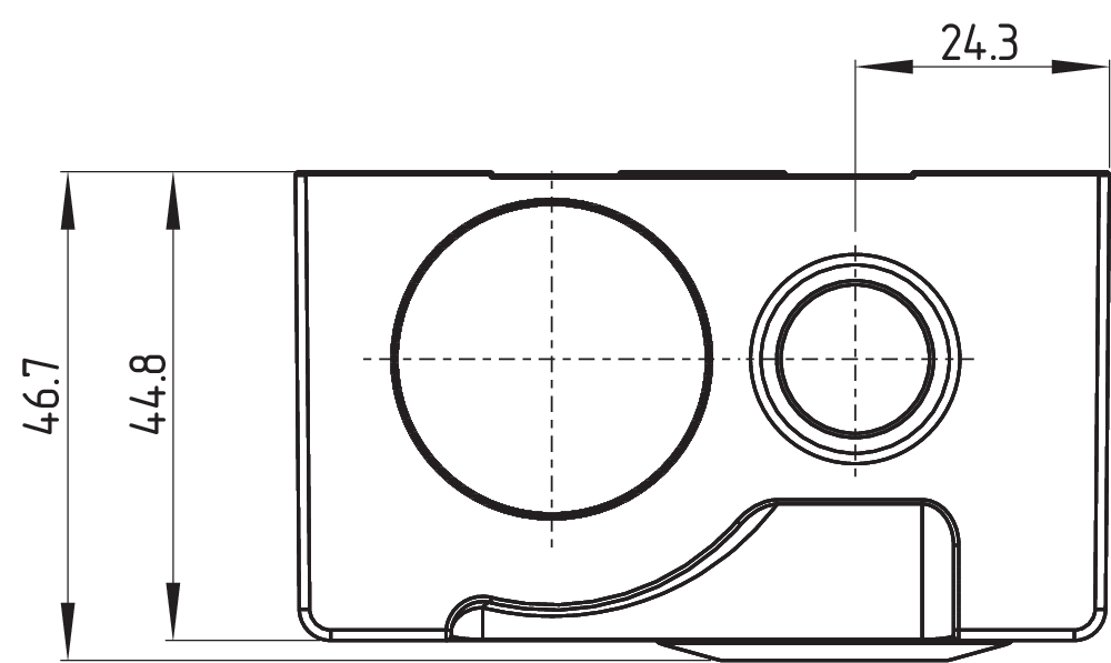
Desenho dimensional componente básico

Desenho dimensional componente básico
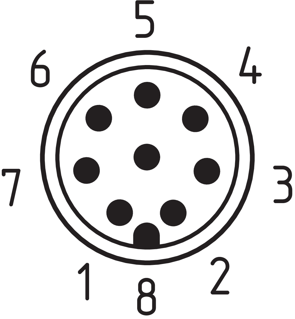
Disposição dos contatos
Video ID: azm400-01
Single device connection (Youtube)

Single device connection (Vimeo)
Video ID: azm400-02
Tolerance to misalignment (Youtube)
Tolerance to misalignment (Vimeo)
Video ID: azm400-03
Opening in case of uptighted doors (Youtube)
Opening in case of uptighted doors (Vimeo)
Video ID: azm400-04
Safety function in case of voltage breakdown (Youtube)
Safety function in case of voltage breakdown (Vimeo)
Video ID: azm400-05
Block driver (Youtube)
Block driver (Vimeo)
Video ID: azm400-06
Cross-fault with controlled shut-down process (Youtube)
Cross-fault with controlled shut-down process (Vimeo)
Video ID: azm400-08
Replacement actuator AZM...-I (Youtube)
Replacement actuator AZM...-I (Vimeo)
Video ID: azm400-09
Teaching of a replacement actuator AZM...-I2 (Youtube)
Teaching of a replacement actuator AZM...-I2 (Vimeo)

103007672 SRB-E-301ST
- Terminais roscados encaixáveis com codificação
- STOP 0 Função
- 1 oder 2 canal conectar
- Botão de arranque / Automático
- 1 contato auxiliar
- 3 contatos de segurança

103009970 SRB-E-201LC
- Terminais roscados encaixáveis com codificação
- STOP 0 Função
- 1 oder 2 canal conectar
- Botão de arranque / Automático
- 2 saídas de segurança 2 A
- 1 saída de sinalização

103009973 SRB-E-204ST
- Terminais roscados encaixáveis com codificação
- STOP 0 Função
- Monitoramento de 4 sensores
- Botão de arranque / Automático
- 2 Saídas de segurança
- 4 saídas de sinalização

103009179 MS-AZM400
- Kit de montagem que consiste em duas chapas de fixação, quatro parafusos escareados M6 e quatro porcas especiais M6
- montagem simples, especialmente em perfis de 40 mm
- Chapas de fixação com orifícios oblongos para alinhamento ideal
103015742 SZ400
- Adequado para a sua montagem no interior e no exterior da zona perigosa
- Próprio para portas basculantes e corrediças
- Para prevenir fechamento acidental, por exemplo, durante a manutenção
- Para planta complexa
- Previne a atuação do comutador
- Identificação de bloqueio com 6 furos circulares

103003508 AZM400-B1
- Atuador para solenóide de segurança AZM400
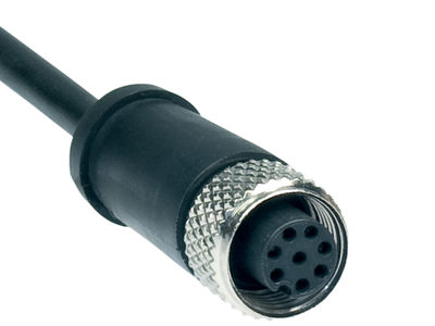
103001389 A-K8P-M12-S-G-10M-BK-1-X-A-4-69-VA
- 10 m
- Cabo de ligação
- 8 pólos
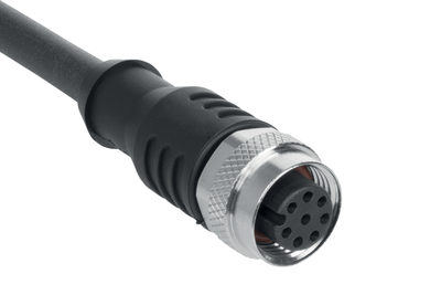
103007359 A-K8P-M12-S-G-10M-BK-2-X-A-4-69
- 10 m
- Cabo de ligação
- 8 pólos
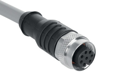
103011413 A-K8P-M12-S-G-10M-GY-1-X-A-4
- 10 m
- Cabo de ligação
- 8 pólos
103011414 A-K8P-M12-S-G-15M-BK-2-X-A-4-69
- 15 m
- Cabo de ligação
- 8 pólos
103011415 A-K8P-M12-S-G-2,5M-BK-2-X-A-4-69
- 2,5 m
- Cabo de ligação
- 8 pólos
103011411 A-K8P-M12-S-G-2,5M-GY-1-X-A-4
- 2,5 m
- Cabo de ligação
- 8 pólos
101210560 A-K8P-M12-S-G-5M-BK-1-X-A-4-69-VA
- 5 m
- Cabo de ligação
- 8 pólos
103007358 A-K8P-M12-S-G-5M-BK-2-X-A-4-69
- 5 m
- Cabo de ligação
- 8 pólos
103011412 A-K8P-M12-S-G-5M-GY-1-X-A-4
- 5,0 m
- Cabo de ligação
- 8 pólos
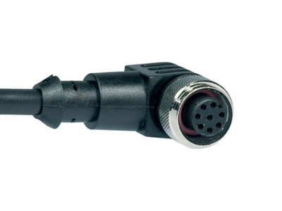
101210561 A-K8P-M12-S-W-5M-BK-1-X-A-4-69-VA
- 5 m
- angular
- Cabo de ligação
- 8 pólos
103011416 A-K8P-M12-S-W-5M-GY-1-X-A-4
- 5 m
- Cabo de ligação
- 8 pólos
103011787 A-K8P-M12-S-G-15M-GY-1-X-A-4
- 15 m
- Cabo de ligação
- 8 pólos
103014823 A-K8P-M12-S-G-15M-BK-1-X-A-4-69-VA
- 15 m
- Cabo de ligação
- 8 pólos
Conteúdo
- 1 Sobre este documento
- 1.1 Função
- 1.2 A quem é dirigido o manual de instruções: pessoal técnico autorizado
- 1.3 Símbolos utilizados
- 1.4 Utilização correcta conforme a finalidade
- 1.5 Indicações gerais de segurança
- 1.6 Advertência contra utilização incorreta
- 1.7 Isenção de responsabilidade
- 2 Descrição do produto
- 2.1 Código para encomenda
- 2.2 Versões especiais
- 2.3 Descrição e utilização
- 2.4 Dados técnicos
- 3 Montagem
- 3.1 Instruções gerais de montagem
- 3.2 Desbloqueio mecânico auxiliar
- 3.3 Desbloqueio elétrico auxiliar E (para -ST2)
- 3.4 Desbloqueio de emergência de fuga -T
- 3.5 Montagem com conjunto de montagem
- 3.6 Dimensões
- 3.7 Atuador e acessórios
- 4 Ligação elétrica
- 4.1 Indicações gerais sobre a ligação elétrica
- 4.2 Possibilidades de comando no modo normal de funcionamento
- 4.3 Requisitos exigidos de uma unidade de avaliação subsequente
- 4.4 Configuração da conexão e acessórios do conector de encaixe
- 4.5 Exemplos de ligação
- 5 Aprendizagem de atuadores / reconhecimento de atuador
- 6 Princípio de atuação e funções de diagnóstico
- 6.1 Modo de trabalho das saídas de segurança
- 6.2 LED's de diagnóstico
- 6.3 Saídas de diagnóstico
- 6.4 Informações de diagnóstico
- 7 Colocação em funcionamento e manutenção
- 7.1 Teste de funcionamento
- 7.2 Manutenção
- 8 Desmontagem e eliminação
- 8.1 Desmontagem
- 8.2 Eliminação
1 Sobre este documento
1.1 Função
O presente documento fornece as informações necessárias para a montagem, a colocação em funcionamento, a operação segura e a desmontagem do dispositivo interruptor de segurança. O manual de instruções que se junta ao dispositivo deve ser mantido sempre em estado legível e guardado em local acessível.
1.2 A quem é dirigido o manual de instruções: pessoal técnico autorizado
Todos os procedimentos descritos neste manual devem ser executados apenas por pessoal formado e autorizado pelo utilizador do equipamento.
Instale e coloque o dispositivo em funcionamento apenas depois de ter lido e entendido o manual de instruções, bem como de se ter familiarizado com as normas de segurança no trabalho e prevenção de acidentes.
A seleção e montagem dos dispositivos, bem como a sua integração na técnica de comando, são vinculados a um conhecimento qualificado da legislação pertinente e requisitos normativos do fabricante da máquina.
1.3 Símbolos utilizados
- Informação, dica, nota: Este símbolo identifica informações adicionais úteis.
- Cuidado: A não observação deste aviso de advertência pode causar avarias ou funcionamento incorreto.
Aviso: A não observação deste aviso de advertência pode causar danos pessoais e/ou danos na máquina.
1.4 Utilização correcta conforme a finalidade
A gama de produtos Schmersal não se destina a consumidores particulares.
Os produtos aqui descritos foram desenvolvidos para assumir funções voltadas para a segurança, como parte integrante de um equipamento completo ou máquina. Está na responsabilidade do fabricante do equipamento ou máquina assegurar o funcionamento correto do equipamento completo.
O dispositivo interruptor de segurança pode ser utilizado exclusivamente conforme as considerações a seguir ou para as finalidades homologadas pelo fabricante. Informações detalhadas sobre a área de aplicação podem ser consultadas no capítulo "Descrição do produto".
1.5 Indicações gerais de segurança
Devem ser observadas as indicações de segurança do manual de instruções bem como as normas nacionais específicas de instalação, segurança e prevenção de acidentes.
- Outras informações técnicas podem ser consultadas nos catálogos da Schmersal ou nos catálogos online na Internet em products.schmersal.com.
Todas as informações são fornecidas sem garantia. Reservado o direito de alterações conforme o desenvolvimento tecnológico.
Observando-se as indicações de segurança, bem como as instruções de montagem, colocação em funcionamento, operação e manutenção, não são conhecidos riscos residuais.
1.6 Advertência contra utilização incorreta
- Em caso de utilização tecnicamente incorreta ou manipulações no dispositivo interruptor não se pode excluir a ocorrência de perigos para pessoas e danos em partes da máquina ou equipamento.
1.7 Isenção de responsabilidade
Não assumimos nenhuma responsabilidade por danos e falhas operacionais causadas por erros de montagem ou devido à não observação deste manual de instruções. Também não é assumida qualquer responsabilidade adicional por danos causados pela utilização de peças sobressalentes ou acessórios não homologados pelo fabricante.
Por motivo de segurança não são permitidas quaisquer reparações, alterações ou modificações efetuadas por conta própria, nestes casos o fabricante exime-se da responsabilidade pelos danos resultantes.
2 Descrição do produto
2.1 Código para encomenda
| Descrição do tipo de produtos: AZM400Z-(1)-(2)-(3)-(4)-(5) |
| (1) | |
| ST | 1 Conector incorporado M12, 8 polos |
| ST2 | 2 Conector incorporado M12, 8 pinos / 5 pinos |
| (2) | |
| sem | Standard codificação |
| I1 | Codificação individual |
| I2 | Codificação individual, aprendizagem múltipla |
| (3) | |
| 1P2P | 1 Saída para diagnóstico e 2 saídas de segurança, comutação p (Só para ST) |
| 2P2P | 2 Saída para diagnóstico e 2 saídas de segurança, comutação p (só para ST2) |
| (4) | |
| sem | Desbloqueio auxiliar |
| T | Dispositivo de desbloqueio de emergência (anti-pânico) |
| BOW | Com furos de montagem para a montagem com cabo Bowden |
| (5) | |
| sem | Sem desbloqueio eletrónico auxiliar (só para ST) |
| E | Com desbloqueio eletrónico auxiliar (só para St2) |
| Atuador | AZM400-B1 |
- As versões AZM400Z-...-BOW só devem ser usadas em combinação com o desbloqueio do cabo Bowden ACC-AZM400-BOW-.M-.M disponível como acessório. Uma utilização sem desbloqueio do cabo Bowden montado não é permitida. As indicações adicionais do manual de instruções para o desbloqueio do cabo Bowden devem ser observadas.
2.2 Versões especiais
Para as versões especiais que não estão listadas no código de modelo, as especificações anteriores e seguintes aplicam-se de forma análoga, desde que sejam coincidentes com a versão de série.
2.3 Descrição e utilização
O dispositivo interruptor de segurança eletrónico sem contacto foi projetado para utilização em circuitos de segurança e para monitorizar e bloquear a posição de dispositivos de proteção móveis.
- Os dispositivos interruptores de segurança são classificados conforme EN ISO 14119 como tipo construtivo de 4 dispositivos de bloqueio. Versões com codificação individual estão classificados como altamente codificados.
As duas primeiras funções de segurança consistem na desativação segura das duas saídas de segurança aquando do desbloqueio ou da abertura do dispositivo de proteção e, com o dispositivo de proteção aberto, da permanência segura em estado desligado (função de bloqueio). A segunda função de segurança (função de bloqueio) consiste no bloqueio seguro de um dispositivo de segurança bloqueado uma vez. O bloqueio do dispositivo de proteção só pode ser desligado num estado sem erros, com um sinal válido para desbloquear.
Com o dispositivo de proteção fechado e um sinal de comando de dois canais aplicado subsequentemente pelo utilizador ou pelo comando, o perno de bloqueio do AZM400 pode ser extraído. Logo que o perno de bloqueio tenha atingido uma profundidade suficiente de penetração no furo de travamento do atuador, o dispositivo de segurança é considerado como fechado.
Com a retenção de segurança AZM400 trata-se de um sistema bi-estável, isso significa que a retenção conserva, em caso de uma falha de energia, o último estado existente.
- A avaliação e o dimensionamento da cadeia de segurança devem ser efetuados pelo utilizador em conformidade com as normas e regulamentos relevantes, de acordo com o nível de segurança requerido. Quando vários sensores de segurança participam da função de segurança, então os valores PFH dos componentes individuais devem ser somados.
- O conceito global do controlo, no qual o componente de segurança será integrado, deve ser validado segundo as normas relevantes.
2.4 Dados técnicos
Homologações - Instruções
|
TÜV cULus FCC IC ANATEL |
Propriedades globais
| Instruções |
EN ISO 13849-1 EN ISO 14119 EN IEC 60947-5-3 EN IEC 61508 |
| informações gerais |
Codificação individual, aprendizagem múltipla |
| Nível de codificação conforme EN ISO 14119 |
Alto |
| Princípio ativo |
Campo magnético RFID |
| Banda de frequência RFID |
125 kHz |
| Potência de envio RFID, máximo |
-6 dBm |
| Material do invólucro |
Metal leve fundido sob pressão |
| Tempo de reação do atuador, máximo |
100 ms |
| Peso bruto |
764 g |
Propriedades globais - Características
| Supervisão de fechamento |
Sim |
| Desbloqueio auxiliar |
Sim |
| Detecção de curto-circuito |
Sim |
| Reconhecimento de curto-circuitos |
Sim |
| Funções de segurança |
Sim |
| Indicação integrada, estado |
Sim |
| Quantidade de sinais de diagnóstico |
1 |
| Número de contatos de segurança |
2 |
Classificação
| Normas, regulamentos |
EN ISO 13849-1 EN IEC 61508 |
Classificação - função de solenoide adicional
| Performance Level, até |
e |
| Categoria de comando |
4 |
| Valor PFH |
1,00 x 10⁻⁹ /h |
| Valor PFD |
9,00 x 10⁻⁵ |
| Safety Integrity Level (SIL), apropriado na |
3 |
| Vida útil |
20 Ano(s) |
Classificação - função de bloqueio
| Performance Level, até |
e |
| Categoria de comando |
4 |
| Valor PFH |
1,80 x 10⁻⁹ /h |
| Valor PFD |
1,60 x 10⁻⁴ |
| Safety Integrity Level (SIL), apropriado na |
3 |
| Vida útil |
20 Ano(s) |
Dados mecânicos
| Princípio de travamento |
biestável |
| Mínima resistência mecânica |
1.000.000 comutações |
| Orientação (resistência mecânica) |
Dos quais, com força transversal Ftransv = 100 N:100.000 ciclos de comutação |
| Distância admissível do bloqueio ao atuador, mínimo |
1 mm |
| Distância admissível do bloqueio ao atuador, máximo |
7 mm |
| Desalinhamento angular entre solenoide e atuador, máximo |
2 ° |
| Distância mínima entre dispositivos |
30 mm |
| Força de engate segundo a EN ISO 14119 |
10.000 N |
| Força de engate, máximo |
13.000 N |
| Força transversal no retorno do pino, máxima (contra porta tensionada) |
300 N |
| Orientação (força transversal máxima no retorno do pino) |
Não aplicável para desbloqueio-, Cabo Bowden- e desbloqueio auxiliar |
| Versão dos parafusos de fixação |
2x M6 |
| Nota (versão dos parafusos de fixação) |
Classe de resistência mín. 10.9 |
| Binário de aperto do parafuso |
8 Nm |
| Orientação |
O binário de aperto máximo do parafuso da tampa (tampa triangular) é de 0,55 Nm. |
Dados mecânicos - dimensões
| Conexão, conector |
Conector M12, 8 polos, codificação-A |
Dados mecânicos - dimensões
| Comprimento do sensor |
46,7 mm |
| Largura de sensor |
77,8 mm |
| Altura do sensor |
156,7 mm |
Ambiente
| Tipo de proteção |
IP66 IP67 |
| Temperatura ambiente |
-20 ... +55 °C |
| Temperatura para armazenar e transportar |
-40 ... +85 °C |
| Máxima umidade relativa |
93 % |
| Orientação (humidade relativa) |
não condensado sem gelo |
| Resistência a vibrações conforme EN 60068-2-6: |
10 … 150 Hz, amplitude 0.35 mm |
| Resistência a impactos |
30 g / 11 ms |
| Classe de proteção |
III |
| Altura de instalação permitida sobre NN, máximo |
2.000 m |
Ambiente - Parâmetros de isolamento
| Medição de isolação da tensão |
32 VDC |
| Medição da rigidez dielétrica da tensão máxima |
0,8 kV |
| Categoria de sobre-tensão |
III |
| Grau de contaminação por sujeira conf. VDE 0100 |
3 |
Dados elétricos
| Tensão de operação |
24 VDC -15 % / +10 % (fonte de alimentação PELV) |
| Corrente de circuito aberto I0, típico |
100 mA |
| Consumo de corrente durante o movimento do perno, valor de pico |
600 mA / 100 ms |
| Medição da tensão de operação |
24 VDC |
| Corrente de curto-circuito de acordo com EN 60947-5-1 {A} |
100 A |
| Isolação externa de cabos e equipamento |
2A gG |
| Atraso na operação, máximo |
1.500 ms |
| Frequência de comutação, máximo |
0,3 Hz |
| Ciclo de fecho/abertura, mínimo |
3 s |
| Tempo de ciclo médio mínimo (com operação contínua) |
20 s |
| Categoria de aplicação DC-12 |
24 VDC / 0,05 A |
| Dados elétricos, máximo |
2 A |
Dados elétricos – Entradas de comando
| Designação, entradas de comando |
E1 e E2 (comutação p), E3 (comutação n) |
| Limiares de comutação das entradas de comando |
−3 V … 5 V (Low) 15 V … 30 V (High) |
| Classificação ZVEI CB24I, descida |
C0 |
| Classificação ZVEI CB24I, fonte |
C1 C2 C3 |
| Consumo de corrente a 24 V, mínimo |
5 mA |
| Consumo de corrente a 24 V, máximo |
10 mA |
| Tempo de discrepância admissível do sinal de entrada, máximo |
10 s |
| Intervalo do impulso de teste, máximo |
40 ms |
| Duração do impulso de teste, máximo |
5 ms |
| Corrente residual admissível do comando |
1,5 mA |
Dados elétricos - Saída de segurança
| Designação, saídas de segurança |
Y1 e Y2 |
| Versão |
À prova de curto-circuito, tipo p |
| Queda de tensão Ud, máximo |
2 V |
| Corrente residual |
0,5 mA |
| Tensão, categoria de aplicação DC-12 |
24 VDC |
| Potência, categoria de aplicação DC-12 |
0,25 A |
| Tensão, categoria de aplicação DC-13 |
24 VDC |
| Potência, categoria de aplicação DC-13 |
0,25 A |
| Intervalo do impulso de teste, típico |
1000 ms |
| Duração do impulso de teste, máximo |
0,5 ms |
| Classificação ZVEI CB24I, fonte |
C2 |
| Classificação ZVEI CB24I, descida |
C1 C2 |
Dados elétricos - saída diagnóstico
| Designação, saídas de diagnóstico |
OUT |
| Versão |
À prova de curto-circuito, tipo p |
| Orientação |
As saídas de diagnóstico não são saídas relevantes para a segurança! |
| Queda de tensão Ud, máximo |
2 V |
| Tensão, categoria de aplicação DC-12 |
24 VDC |
| Potência, categoria de aplicação DC-12 |
0,05 A |
| Tensão, categoria de aplicação DC-13 |
24 VDC |
| Potência, categoria de aplicação DC-13 |
0,05 A |
Indicação de Estado
| Orientação (LED indicador do estado) |
Estado operacional : LED amarelo Falha avaria funcional: LED vermelho Tensão de alimentação UB: LED verde indica |
Descrição dos pinos
| PIN 1 |
A1 Tensão de alimentação UB |
| PIN 2 |
E1 1 |
| PIN 3 |
A2 GND |
| PIN 4 |
Y1 Saída de segurança 1 |
| PIN 5 |
OUT Saída de diagnóstico |
| PIN 6 |
E3 3 |
| PIN 7 |
Y2 Saída de segurança 2 |
| PIN 8 |
E2 2 |
Orientação UL
FCC/IC - Nota
Este dispositivo está em conformidade com a secção 15 das diretivas da Federal Communications Commission (FCC) e contém transmissores/recetores isentos de licença que estão em conformidade com a(s) norma(s) RSS do ISED (Innovation, Science and Economic Development) do Canadá.
O funcionamento está sujeito às duas condições seguintes:
(1) Este dispositivo não pode emitir sinais de interferência prejudiciais e
(2) Este dispositivo deve poder tolerar sinais de interferência. Estes incluem também sinais de interferência que podem causar um funcionamento não desejado do dispositivo.
A uma distância mínima de 100 mm durante o funcionamento, este dispositivo respeita os valores limite para estimulação nervosa (ISED SPR-002). Alterações ou adaptações que não tenham sido expressamente aprovadas pela K.A. Schmersal GmbH & Co. KG podem anular a autorização do utilizador para operar o dispositivo.
O transmissor/recetor isento de licença integrado neste dispositivo cumpre os requisitos em vigor da "Radio Standards Specification" da organização Innovation, Science and Economic Development Canada (ISED) aplicáveis a equipamentos de rádio. O funcionamento é permitido nas duas seguintes condições:
(1) O dispositivo não pode criar interferências.
(2) O dispositivo deve suportar as interferências de rádio recebidas, mesmo que estas possam prejudicar o seu modo de funcionamento.
Este dispositivo cumpre os requisitos de valores limites de exposição para estimulação do tecido nervoso (ISED CNR-102) em processos com uma distância mínima de 100 mm.
No caso de alterações ou modificações que não tenham sido expressamente autorizadas pela K.A. Schmersal GmbH & Co. KG, a autorização do utilizador para operar o dispositivo pode ser invalidada.
3 Montagem
3.1 Instruções gerais de montagem
- Favor observar as indicações relacionadas nas normas EN ISO 12100, EN ISO 14119 e EN ISO 14120.
A posição de uso é opcional.
- Deve ser evitada a acumulação de sujidade de grão fino na área do perno.
Por isso, é previsível, num tal caso de uma montagem vertical, na qual o perno se extrai de baixo para cima.
Para a fixação da retenção de segurança estão disponíveis dois furos de fixação para parafusos M6.
- Os parafusos M6 devem corresponder, pelo menos, à classe de resistência 10.9. O binário de aperto dos parafusos M6 é de 8 Nm.
- O atuador deve ser fixado de modo que não possa ser solto (utilização de parafusos não amovíveis, adesivo, furação, pinos de fixação) do dispositivo de proteção e travado contra deslocamento.
- A utilização em temperaturas negativas é apenas permitida com frio seco. Isto deve ser levado em consideração pelo cliente ao instalar o comutador de segurança.
| Direções de atuação e distâncias do interruptor | |
|---|---|
| O AZM400 é funcional dentro dos seguintes limites de tolerância: | |
| Eixo X | ± 4 mm |
| Eixo Y | ± 4 mm |
| Eixo Z | Distância entre atuador e retenção de segurança 1 … 7 mm num deslocamento angular máx. de 2° |
- As curvas de aproximação mostram a faixa de deteção típica do atuador em dependência com a direção de aproximação.
- A direção de entrada só é admissível a partir da direção X e Y.
- A distância de um máx. de 7 mm entre o atuador e a retenção de segurança deve ser respeitada, para que a força de fecho indicada e a função de retenção segura seja alcançada conforme SIL 3. A construção da porta de proteção deve estar disposta, de modo que não seja possível deslocar tanto o dispositivo de segurança com o atuador para o eixo Z, que a distância entre a retenção e o atuador seja maior do que 7 mm.
- O dispositivo de segurança deve ser estruturalmente concebido, de modo que um perigo de esmagamento que poderia advir do processo do perno, está fora de questão.
Montagem das unidades de atuador
Ver o manual de instruções da respetiva unidade de atuador.
Para evitar uma influência causada pelo sistema bem como a redução das distâncias de comutação, por favor observar as seguintes indicações:
- Peças de metal e campos magnéticos nas imediações do atuador e o solenóide de segurança podem influenciar a distância do interruptor ou levar a avarias funcionais.
- Manter longe de aparas de metal.
Distância mínima entre duas retenções de segurança
ou outros sistemas com mesma frequência (125 kHz): 30 mm.
3.2 Desbloqueio mecânico auxiliar
Para a instalação da máquina, a retenção de segurança pode ser desenergizada para desbloquear. Ao girar a chave triangular do desbloqueio auxiliar com ajuda da chave triangular para a posição q a retenção de segurança é desbloqueada. Apenas depois de girar o desbloqueio auxiliar de volta para a posição inicial p, a função de bloqueio normal é reposta.
A chave triangular TK-M5 (101100887) está disponível como acessório.
- Estruturalmente, pode ser indicado, de futuro, um desbloqueio auxiliar ativo através dos LEDs, após girar para trás o desbloqueio auxiliar (todos os três LEDs piscam). Estes são movidos para trás após um novo comando através das entradas de comando.
- Não girar o desbloqueio auxiliar para além do batente.
| Posição bloqueada | Posição desbloqueada |
|---|---|
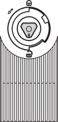 |  |
3.3 Desbloqueio elétrico auxiliar E (para -ST2)
O desbloqueio auxiliar elétrico pode ser realizado através de uma alimentação auxiliar. Para esse efeito, está disponível a entrada de alimentação auxiliar H1.
O AZM400 deve ser ligado exclusivamente com a fonte de alimentação auxiliar, de modo que o pino de bloqueio retroceda independentemente das entradas de comando. Em seguida, não são possíveis quaisquer outras ações, as saídas de segurança e diagnóstico permanecem desligadas.
Estado do sistema (válido apenas durante a fase de inicialização):
| Alimentação principal | Alimentação auxiliar | Estado do sistema |
|---|---|---|
| 0 V | 0 V | O perno de bloqueio permanece na posição (saídas de segurança desligadas) |
| 24 V | 0 V | dependente de entradas de comando |
| 0 V | 24 V | O perno de bloqueio retorna automaticamente (desbloqueio) |
| 24 V | 24 V | O perno de bloqueio permanece na posição (erro) |
- A cablagem e comando do desbloqueio auxiliar é uma validação de tecnologia de segurança sujeita a validação. O sinal da alimentação auxiliar via UPS é processado de forma diferente internamente para que os curtos-circuitos não sejam detetados.
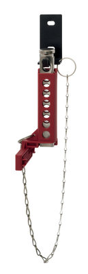
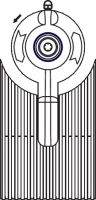
3.4 Desbloqueio de emergência de fuga -T
Desbloqueio de emergência de fuga para a aplicação dentro da zona de perigo.
Para o desbloqueio de emergência de fuga rodar a alavanca vermelha em sentido da seta até ao batente. O perno move-se através de força de mola na posição desbloqueada, para que o dispositivo de proteção possa ser aberto nesta posição e as saídas de segurança sejam desativadas. Na posição desbloqueada, o dispositivo de proteção está protegido contra bloqueio acidental.
- Não girar para além do batente!
| Posição bloqueada | Posição desbloqueada |
|---|---|
 |  |
- Para garantir uma função correta do desbloqueio de emergência de fuga -T, a porta de proteção não se deve encontrar num estado mecanicamente tensionado.
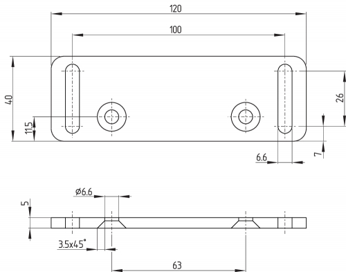
3.5 Montagem com conjunto de montagem
Para perfis de alumínio de 40 mm pode ser utilizado o conjunto opcional de montagem MS-AZM400. Este é composto por duas placas de montagem, incluindo quatro parafusos e quatro porcas.

3.6 Dimensões
Todas as medidas em mm.
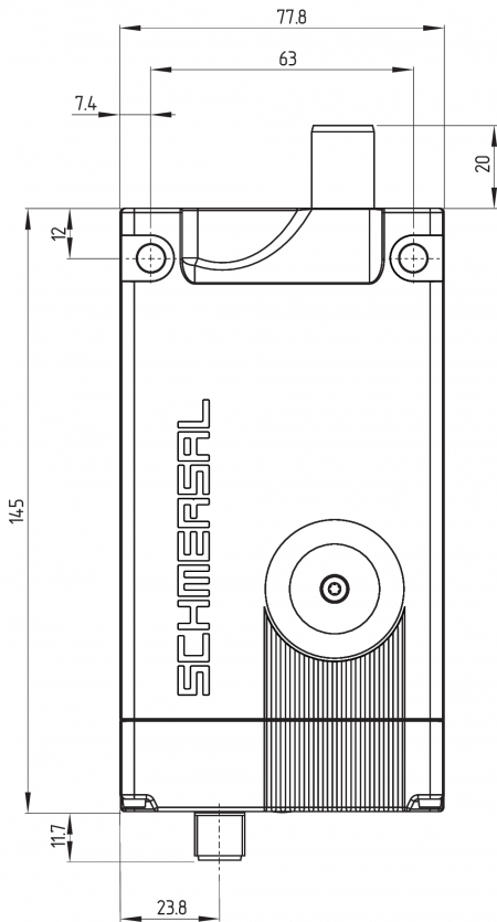
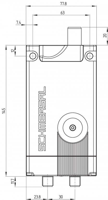

AZM400 com desbloqueio de fuga em emergência
| Legenda | |
|---|---|
| A1 | Desbloqueio auxiliar com tampa |
| A2 | Dispositivo de desbloqueio de emergência (anti-pânico) |
| B | Perno de bloqueio (extraído) |
| C1 | Conector incorporado M12, 8 polos |
| C2 | Conector incorporado M12, 5 polos |
| D | Sensor RFID |
3.7 Atuador e acessórios
Atuador AZM400-B1 (não incluído no fornecimento)

Placa de montagem, parte integrante do conjunto de montagem MS-AZM400
(disponíveis como acessórios)
Bloqueador SZ400
(disponíveis como acessórios)
Para mais informação detalhada e indicações de montagem ver manual de instruções SZ400

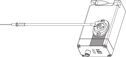
Desbloqueio de cabo Bowden ACC-AZM400-BOW-.M-.M
(disponível como acessório)
As indicações adicionais do manual de instruções para o desbloqueio do cabo Bowden devem ser observadas.
4 Ligação elétrica
4.1 Indicações gerais sobre a ligação elétrica
- A ligação elétrica pode ser efetuada apenas em estado desenergizado por pessoal técnico autorizado.
As entradas de tensão A1 (e H1 em AZM400Z-ST2..), bem como as entradas de comando E1, E2 e E3 devem ser protegidas contra sobretensão permanente. Por isso devem ser utilizadas fontes de alimentação PELV conforme EN 60204-1,
As saídas de segurança podem ser utilizadas diretamente para a interligação da parte do comando do utilizador relevante para a segurança.
A proteção do cabo elétrico necessária deve ser fornecido na instalação.
4.2 Possibilidades de comando no modo normal de funcionamento
Devido às três entradas de comando E1, E2 e E3 para controlo da função de bloqueio, é possível utilizar diversas opções de ativação, para poder operar o AZM400 em diferentes comandos de segurança. A função das entradas de comando é igual para as duas variantes ST e ST2. A ativação operacional das entradas de comando, de acordo com a tabela seguinte, leva ao desbloqueio da retenção.
| Estado de entrada | Variante P/P | Variante P/N | |||
|---|---|---|---|---|---|
| E1 | E2 | E3 | E1 = E2 | E3 | |
| Bloquear | aberta | aberta | GND | aberta | aberta |
| Desbloquear | 24 V | 24 V | GND | 24 V | GND |
Utilização de saídas de segurança do tipo P/P:
Controlo de segurança

Utilização dos comandos de segurança do tipo P/N:
Controlo de segurança

- As saídas do comando utilizadas devem corresponder ao nível de desempenho (PL) necessário no dispositivo de segurança. Para atingir o PL e, o comando deve ser disposto por saídas testadas, uma vez que o AZM400 não as testa por si próprio.
- Independentemente da variante utilizada, devem ser observadas as indicações do manual de instruções do comando utilizado.
Estes poderão ser, por exemplo:
- Cabos instalados protegidos
- Intervalo mínimo de teste todas as 24 horas
- etc.
Percurso do bloco
Se o perno de bloqueio não alcançar o estado "bloqueado" na primeira tentativa, o AZM400 faz uma outra tentativa por iniciativa própria. Se a segunda tentativa também falhar, o AZM400 comunica uma falha (ver Tabela 2).
Após uma falha, é necessária uma mudança de estado das entradas de comando para uma nova extração do perno de bloqueio.
Num fecho lento do dispositivo de segurança, pode chegar-se a um percurso do bloco, se a abertura do atuador ainda não se encontrar à frente do perno extraído (ver capítulo "Direções de atuação e distâncias do interruptor").
Desbloqueio após a ligação
Se o AZM400 se encontrar já na posição de bloqueio após a ligação, em cada caso, o dispositivo deve ser, em primeiro lugar, desbloqueado e novamente desbloqueado, para verificar a causalidade dos sinais de acionamento e a profundidade de inserção correta do perno de bloqueio. Após um Power-On na posição de bloquei o LED amarelo pisca.
4.3 Requisitos exigidos de uma unidade de avaliação subsequente
Entrada de segurança de dois canais, adequada para saídas de semicondutores tipo 2p (OSSD)
Os solenóides de segurança testam suas saídas de segurança através de um corte cíclico. Por isso não é necessário uma deteção de curto-circuito na unidade de avaliação. Os tempos de impulso de teste de ≤ 0,4 ms são tolerados pela avaliação. O tempo de impulso de teste dos encravamentos de segurança prolonga-se adicionalmente dependendo do comprimento do cabo e da capacidade do cabo utilizado.
- Configuração do comando de segurança
Na ligação do solenóide de segurança nas unidades de avaliação de segurança eletrónicas recomendamos o ajuste de um período de discrepância de 100 ms. As entradas de segurança da unidade de avaliação têm de poder ocultar um impulso de teste de aprox < 1 ms.
- Informações técnicas acerca da seleção de módulos de avaliação de segurança adequados podem ser consultadas nos catálogos da Schmersal ou no catálogo online na Internet em products.schmersal.com.
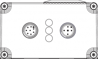
4.4 Configuração da conexão e acessórios do conector de encaixe
Configuração da ligação da variante AZM400Z-ST-...
| Função de dispositivo interruptor de segurança | Pinagem do conector incorporado M12. 8-pólos | Códigos de cores dos conectores de encaixe Schmersal segundo a DIN 47100 | Possíveis códigos de cores de outros conectores de encaixe disponíveis no mercado acordo com EN 60947-5-2 | |
|---|---|---|---|---|
 | ||||
| A1 | UB | 1 | WH | BN |
| E1 | Entrada de comando 1 | 2 | BN | WH |
| A2 | GND | 3 | GN | BU |
| Y1 | Saída de segurança 1 | 4 | YE | BK |
| OUT | Saída para diagnóstico | 5 | GY | GY |
| E3 | Entrada de comando 3 | 6 | PK | PK |
| Y2 | Saída de segurança 2 | 7 | BU | VT |
| E2 | Entrada de comando 2 | 8 | RD | OR |
Configuração da ligação da variante AZM400Z-ST2-…
| Função de dispositivo interruptor de segurança | Pinagem do conector incorporado M12, 8-polos | Códigos de cores dos conectores de encaixe Schmersal segundo a DIN 47100 | Possíveis códigos de cores de outros conectores de encaixe disponíveis no mercado acordo com EN 60947-5-2 | |
|---|---|---|---|---|
| ||||
| OUT2 | Saída de diagnóstico 2 | 1 | WH | BN |
| E1 | Entrada de comando 1 | 2 | BN | WH |
| - | (Não conectado) | 3 | GN | BU |
| Y1 | Saída de segurança 1 | 4 | YE | BK |
| OUT1 | Saída de diagnóstico 1 | 5 | GY | GY |
| E3 | Entrada de comando 3 | 6 | PK | PK |
| Y2 | Saída de segurança 2 | 7 | BU | VT |
| E2 | Entrada de comando 2 | 8 | RD | OR |
| Função de dispositivo interruptor de segurança | Pinagem do conector incorporado M12, 5-polos | Códigos de cores dos conectores de encaixe Schmersal segundo a DIN 47100 | Possíveis códigos de cores de outros conectores de encaixe disponíveis no mercado acordo com EN 60947-5-2 | |
|---|---|---|---|---|
 | ||||
| A1 | UB | 1 | BN | WH |
| H2 | GNDhe | 2 | WH | BN |
| A2 | GND | 3 | BU | GN |
| H1 | Uhe | 4 | BK | YE |
| FE | Ligação à terra funcional 3 | 5 | GY | GY |
Acessórios condutores de ligação
| Condutores de ligação com tomada (fêmea) M12, 8-polos – 8 x 0,25 mm², IP67 / IP69 | |
|---|---|
| Comprimento do condutor | Código de encomenda |
| 2,5 m | 103011415 |
| 5,0 m | 103007358 |
| 10,0 m | 103007359 |
| 15,0 m | 103011414 |
| Condutores de ligação com tomada (fêmea) M12, 5-polos – 5 x 0,34 mm² | |
|---|---|
| Comprimento do condutor | Código de encomenda |
| 5,0 m | 103010816 |
| 10,0 m | 103010818 |
Outras versões, noutros comprimentos e com saída de cabo angular disponíveis sob consulta.
4.5 Exemplos de ligação
Os exemplos de aplicação mostrados são sugestões que não eximem o utilizador de verificar a ligação quanto à sua respetiva adequação para cada caso individual.
Exemplo de ligação 1: AZM400Z-ST

| Legenda - Configuração da ligação | |
|---|---|
| Conector incorporado M12, 8 polos | |
| A1 | UB |
| A2 | GND |
| E1 | Entrada de comando 1 |
| E2 | Entrada de comando 1 |
| E3 | Entrada de comando 2 |
| Y1 | Saída de segurança 1 |
| Y2 | Saída de segurança 2 |
| OUT | Saída para diagnóstico |
Exemplo de ligação 2: AZM400Z-ST2
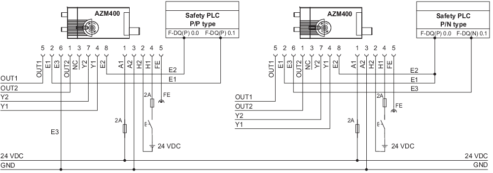
| Legenda - Configuração da ligação | |||
|---|---|---|---|
| Conector incorporado M12, 8 polos | Conector incorporado M12, 5 polos | ||
| E1 | Entrada de comando 1 | A1 | UB |
| E2 | Entrada de comando 2 | A2 | GND |
| E3 | Entrada de comando 3 | H1 | Uhe |
| Y1 | Saída de segurança 1 | H2 | GNDhe |
| Y2 | Saída de segurança 2 | FE | Ligação à terra funcional |
| OUT1 | Saída de diagnóstico 1 | ||
| OUT2 | Saída de diagnóstico 2 | ||
5 Aprendizagem de atuadores / reconhecimento de atuador
Solenóides de segurança com codificação standard estão prontos a funcionar no estado de fornecimento.
Solenóides de segurança e atuadores codificados individualmente passam por aprendizagem mútua conforme a sequência a seguir:
- Desligar o solenóide de segurança e realimentar com tensão.
- Colocar o atuador na área de captação. O processo de aprendizagem é sinalizado no solenóide de segurança, LED verde desligado, LED vermelho aceso, LED amarelo intermitente (1 Hz).
- Após 10 segundos, pulsos de pisca-pisca em ciclo mais curto (3 Hz) pedem o desligamento da tensão de operação do solenóide de segurança. (Caso o desligamento não seja efetuado dentro de 5 minutos, o solenóide de segurança interrompe o processo de aprendizagem e sinaliza um atuador errado piscando 5x vermelho.)
- Ao religar a tensão de operação, o atuador tem de ser novamente captado para ativar o código de atuador aprendido. O código ativado é então guardado definitivamente.
Na opção de encomenda -I1 a atribuição assim efetuada entre o dispositivo interruptor de segurança e atuador é irreversível.
Na opção de encomenda -I2 o processo de aprendizagem para um novo atuador pode ser repetido de modo ilimitado. Quando da aprendizagem de um novo atuador, o código anterior é eliminado. De seguida, um bloqueio de habilitação de dez minutos assegura uma elevada proteção contra manipulação. O LED verde pisca até decorrer o tempo do bloqueio de habilitação e o novo atuador ser captado. Em caso de interrupção da alimentação de tensão durante o decurso dos 10 minutos de proteção contra manipulação, posteriormente a contagem é reiniciada.
- Encontre medidas organizativas contra uma possível manipulação com outros elementos do atuador, se for utilizada uma variante com codificação padrão.
6 Princípio de atuação e funções de diagnóstico
6.1 Modo de trabalho das saídas de segurança
No encravamento de segurança AZM400 as entradas de segurança são desligadas de imediato pelo sinal de desbloqueio. O dispositivo de segurança desbloqueado pode ser novamente bloqueado enquanto o atuador estiver na área de deteção do encravamento de segurança. As saídas de segurança serão então novamente ligadas.
Com as saídas de segurança já ligadas, as falhas que momentaneamente não prejudicam a função segura do solenóide de segurança (p. ex., temperatura ambiente muito alta, saída de segurança ligada em potencial externo, curtos-circuitos) levam um aviso de alerta, ao corte da saída de diagnóstico OUT da variante ST ou OUT2 da variante ST2 e a um corte retardado das saídas de segurança. As saídas de segurança são desligadas quando o alerta de falha persiste por 30 minutos. A combinação de sinal, saída de diagnóstico OUT da variante ST ou OUT2 da variante ST2 desligada e as saídas de segurança ainda ligadas pode ser utilizada para deslocar a máquina em posição de paragem ordenada. Após a resolução do erro, a mensagem de erro é confirmada pela abertura e fecho da porta de proteção respetiva ou pela ativação ou desativação da tensão de serviço.
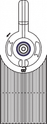
6.2 LED's de diagnóstico
O solenóide de segurança sinaliza a condição de operação, mas também avarias, através de três LED's com cores diferentes.
| Verde (Potência) | Tensão de alimentação presente |
| Amarelo (Estado) | condição de operação |
| Vermelho (Falha) | Falha (v. tabela 2: mensagens de falha / códigos de luz intermitente LED de diagnóstico vermelho) |
| Disposição dos LED's | |
|---|---|
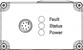 |  |
6.3 Saídas de diagnóstico
A saída de diagnóstico OUT ou OUT1 ou OUT2 da variante ST2 à prova de curto-circuito, pode ser utilizada para indicação centralizada ou funções de controlo, p. ex., num PLC. Ela reproduz o estado de comutação conforme a tabela 1.
As saídas para diagnóstico OUT ou OUT1 e OUT2 não são nenhumas saídas relevantes para a segurança!
Falhas
Falhas que causam a perda de garantia de funcionamento do encravamento de segurança (falhas internas), levam à desconexão imediata das saídas de segurança. Uma falha que não prejudica momentaneamente o funcionamento seguro do encravamento de segurança (p.ex. temperatura ambiente demasiado elevada, saída de segurança no potencial, curto-circuito) leva a uma desconexão retardada (ver tabela 2). Depois de eliminada a falha, a mensagem de falha é confirmada com a abertura da respetiva porta de proteção.
Falhas nas saídas de comando não levam à desconexão das saídas de segurança.
Alerta de falha
Ocorreu uma falha que, após o decurso de 30 minutos, leva ao corte das saídas de segurança (LED „Fault“ pisca, ver tabela 2). As saídas de segurança permanecem ligadas (máx. 30 minutos). O objetivo é conduzir um corte controlado. Se a causa for eliminada, o alerta de falha é suprimido.
6.4 Informações de diagnóstico
| Tabela 1: Informações de diagnóstico do solenóide de segurança AZM400 | ||||||||
|---|---|---|---|---|---|---|---|---|
| Estado do sistema° | Sinal de comando | LED | Saídas de segurança | Saídas de diagnóstico | ||||
| Função de bloqueio | Verde | Vermelho | Amarelo | Y1, Y2 | Variante ST OUT | Variante ST2 OUT1 | Variante ST2 OUT2 | |
| Porta aberta e desbloqueada (O perno está inserido) | Desbloquear | liga | desliga | desliga | 0 V | 0 V | 0 V | 0 V |
| Porta fechada e desbloqueada (O perno está inserido) | Desbloquear | liga | desliga | intermitente | 0 V | 24 V | 0 V | 0 V |
| Tür geschlossen; Sperrvorgang aktiv (Perno em movimento de progressão) | Bloquear | liga | desliga | intermitente | 0 V | 0 V | 0 V | 24 V |
| Porta fechada e bloqueada (O perno está extraído) | Bloquear | liga | desliga | liga | 24 V | 24 V | 24 V | 24 V |
| Porta fechada, processo de desbloqueio ativo (Perno em movimento de regressão) | Desbloquear | liga | desliga | intermitente | 0 V | 0 V | 24 V | 24 V |
| Estados de erro: | ||||||||
| Alerta de falha 1) | Sem significado | liga | intermitente 2) | liga | 24 V | 0 V | 24 V | 0 V |
| Falhas | Sem significado | liga | intermitente 2) | desliga | 0 V | 0 V | 24 V | 0 V |
| Desbloqueio mecânico, de emergência de fuga ou do cabo Bowden ativo | Sem significado | intermitente | intermitente | intermitente | 0 V | 24 V | 0 V | 24 V |
| Desbloqueio eletrónico auxiliar ativo | Sem significado | intermitente | intermitente | intermitente | 0 V | - | 0 V | 0 V |
| Aprendizagem do atuador na versão I1/I2: | ||||||||
| Aprendizagem do atuador iniciada | Desbloquear | desliga | liga | pisca devagar | 0 V | 0 V | 0 V | 0 V |
| A aprendizagem do atuador pode ser encerrada | Desbloquear | desliga | liga | pisca rapidamente | 0 V | 0 V | 0 V | 0 V |
| Apenas I2: o atuador está programado (decorre o período de proteção contra manipulação) | Desbloquear | intermitente | desliga | desliga | 0 V | 24 V | 0 V | 24 V |
1) após 30 min: Paragem devido a falha 2) v. código de intermitência | ||||||||
| Tabela 2: Mensagens de falha / códigos de luz intermitente LED de diagnóstico vermelho | |||
|---|---|---|---|
| Códigos de luz intermitente (vermelho) | Designação | desconexão automático após | Causa da falha |
| 1 pulso intermitente | Falha (alerta de falha) na saída Y1 | 30 min | Falha do teste de saída ou tensão na saída Y1, apesar de a saída estar desligada. |
| 2 pulsos intermitentes | Falha (alerta de falha) na saída Y2 | 30 min | Falha do teste de saída ou tensão na saída Y2, apesar de a saída estar desligada. |
| 3 pulsos intermitentes | Falha (alerta de falha) curto-circuito | 30 min | curto-circuito entre os cabos de saída ou falha nas duas saídas. |
| 4 pulsos intermitentes | Falha (alerta de falha) sobretemperatura | 30 min | A medição de temperatura resultou em temperatura interna demasiado elevada |
| 5 pulsos intermitentes | Falha no atuador | 0 min | Atuador errado ou com defeito |
| 6 pulsos intermitentes | Erro nas entradas de comando / desbloqueio eletrónico auxiliar | - | Estados de entrada dos comandos de entrada e/ou do desbloqueio eletrónico auxiliar inválidos |
| 7 pulsos intermitentes | Erro no reconhecimento de atuador | 0 min | Distância entre AZM400 e o atuador muito grande; campos magnéticos dispersos evitam a deteção |
| 8 pulsos intermitentes | Falha no percurso do bloco | 0 min | Atuador não orientado corretamente para o solenóide de segurança |
| 9 pulsos intermitentes | Erro sobretrensão/subtensão | 0 min | Tensão de alimentação fora das especificações |
| Vermelho permanente | Falha interna | 0 min | Dispositivo com defeito |
| Tabela 2.1: Mensagens de falha / códigos de luz intermitente LED amarela | |||
|---|---|---|---|
| Código de luz intermitente (amarelo) | Designação | desconexão automático após | Causa da falha |
| Amarelo a piscar rápido (2 Hz) | Falha de entradas de comando | 0 min | Frequência demasiado elevada (> 0,3 Hz) nas entradas de comando E1 e E2 |
7 Colocação em funcionamento e manutenção
7.1 Teste de funcionamento
O dispositivo interruptor de segurança deve ter a sua função de segurança testada. Neste procedimento deve-se assegurar previamente o seguinte:
- Verificar o deslocamento lateral máx. da unidade do atuador e do solenóide de segurança.
- Verificar o deslocamento angular máx.
- Assegurar-se, que não é possível levantar o atuador no eixo Z através dos pernos extraídos.
- Verificar o assento firme do solenóide de segurança e do atuador.
- Verificar a integridade das ligações dos cabos
- Verificar se o invólucro do interruptor está danificado.
- Remoção dos resíduos.
- Para variantes com desbloqueio de emergência de fuga e de desbloqueio de emergência deve ser observado também:
O dispositivo de proteção deve poder ser aberto dentro da zona de perigo; não pode ser possível bloquear o dispositivo de proteção por dentro.
7.2 Manutenção
Com a instalação correta e utilização conforme a finalidade, o dispositivo interruptor de segurança funciona livre de manutenção.
Recomendamos realizar um teste visual e funcional em intervalos regulares, através dos seguintes passos:
- Verificar o assento firme do solenóide de segurança e do atuador.
- Verificar o deslocamento lateral máx. da unidade do atuador e do solenóide de segurança.
- Verificar o deslocamento angular máx.
- Assegurar-se, que não é possível levantar o atuador no eixo Z através dos pernos extraídos.
- Verificar a integridade das ligações dos cabos
- Verificar se o invólucro do interruptor está danificado.
- Remoção dos resíduos.
- Em todas as fases da vida operacional do dispositivo interruptor de segurança devem ser tomadas medidas organizativas e construtivas de proteção contra manipulação e manipulação do dispositivo de proteção, por exemplo, através da utilização de um atuador substituto.
- Os equipamentos danificados ou defeituosos devem ser substituídos.
8 Desmontagem e eliminação
8.1 Desmontagem
O dispositivo interruptor de segurança deve ser desmontado apenas em estado desenergizado.
8.2 Eliminação
- O dispositivo interruptor de segurança deve ser eliminado de modo tecnicamente correto, conforme a legislação e normas nacionais.
| EU Declaration of Conformity |  |
| Original | K.A. Schmersal GmbH & Co. KG Möddinghofe 30 42279 Wuppertal Germany Internet: www.schmersal.com |
| Declaration: | We hereby certify that the hereafter described components both in their basic design and construction conform to the applicable European Directives. |
| Name of the component: | AZM400 |
| Type: | See ordering code |
| Description of the component: | Interlocking device with safe locking function |
| Relevant Directives: | Machinery Directive | 2006/42/EC |
| RED-Directive | 2014/53/EU | |
| RoHS-Directive | 2011/65/EU |
| Applied standards: | EN 60947-5-3:2013 EN ISO 14119:2013 EN ISO 14119:2025 EN 300 330 V2.1.1:2017 EN ISO 13849-1:2023 EN 61508 parts 1-7:2010 |
| Notified body for Type Examination: | TÜV Rheinland Industrie Service GmbH Am Grauen Stein, 51105 Köln ID n°: 0035 |
| EC-Type Examination Certificate: | 01/205/5467.02/25 |
| Person authorised for the compilation of the technical documentation: | Oliver Wacker Möddinghofe 30 42279 Wuppertal |
| Place and date of issue: | Wuppertal, August 12, 2025 |
| Authorised signature Philip Schmersal Managing Director |
ACE Schmersal Eletroeletrônica Ind. Ltda, Av. Brasil, nº 815, Jardim Esplanada – CEP 18557-646 Boituva/SP
Os dados e informações fornecidas foram cuidadosamente verificados. No entanto as imagens podem divergir do original. Informações técnicas adicionais podem ser encontradas no manual. Alterações técnicas e erros são possíveis.
Gerado em 22/08/2025 16:41