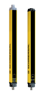
RSS 36-AD-ST-AS

RSS 36-AD-ST-AS
| Product type description: RSS 36-(1)-ST-AS-(2) |
| (1) | |
| without | Standard coding |
| AD | Standard coding, actuator detection |
| I1 | Individual coding |
| I2 | Individual coding, for multiple applications |
| (2) | |
| without | Without latching |
| R | With latching, latching force approx. 18 N |
- Universal coding with RFID technology
- without latching
- Thermoplastic enclosure
- RFID-technology for needs-based protection against tampering
- optionally with integrated magnetic latching
Ordering data
| Product type description |
RSS 36-AD-ST-AS |
| Article number (order number) |
103001535 |
| EAN (European Article Number) |
4030661426396 |
| eCl@ss number, version 12.0 |
27-27-46-01 |
| eCl@ss number, version 11.0 |
27-27-24-03 |
| eCl@ss number, version 9.0 |
27-27-24-03 |
| ETIM number, version 7.0 |
EC001829 |
| ETIM number, version 6.0 |
EC001829 |
Approvals - Standards
| Certificates |
TÜV cULus ASi-SaW ECOLAB ANATEL |
General data
| Standards |
EN IEC 62026-2 EN ISO 13849-1 EN ISO 14119 EN IEC 60947-5-3 EN IEC 61508 |
| Coding |
Universal coding |
| Coding level according to EN ISO 14119 |
Low |
| Working principle |
RFID |
| Frequency band RFID |
125 kHz |
| Transmitter output RFID, maximum |
-6 dB/m |
| Housing construction form |
Block |
| Installation conditions (mechanical) |
not flush |
| Housing material |
Plastic, glass-fibre reinforced thermoplastic, self-extinguishing |
| Reaction time, maximum |
100 ms |
| Duration of risk, maximum |
200 ms |
| Gross weight |
104 g |
General data - Features
| Safety functions |
Yes |
| Integral system diagnostics, status |
Yes |
| Number of actuating directions |
3 |
| Safety classification |
| Vorschriften |
EN ISO 13849-1 EN IEC 61508 |
| Performance Level, up to |
e |
| Category |
4 |
| PFH value |
5.13 x 10⁻¹⁰ /h |
| PFD value |
3.24 x 10⁻⁵ |
| Safety Integrity Level (SIL), suitable for applications in |
3 |
| Mission time |
20 Year(s) |
Mechanical data
| Mechanical life, minimum |
1,000,000 Operations |
| Note (Mechanical life) |
Actuating speed < 0.25 m/s Operations for door weights ≤ 5 kg |
| Type of the fixing screws |
2x M4 (cylinder head screws with washers DIN 125A / form A) |
| Tightening torque of the fixing screws, minimum |
2.2 Nm |
| Tightening torque of the fixing screws, maximum |
2.5 Nm |
Mechanical data - Switching distances
| Switch distance, typical |
12 mm |
| Assured switching distance "ON" Sao |
10 mm |
| Assured switching distance "OFF" Sar |
20 mm |
| Note (switching distance) |
All switching distances in accordance EN IEC 60947-5-3 |
| Hysteresis (Switching distance), maximum |
2 mm |
| Repeat accuracy R |
0.5 mm |
| Note (Repeat accuracy R) |
Axial offset: The long side allows for a maximum height misalignment (x) of sensor and actuator of 8 mm (e.g. mounting tolerance or due to guard door sagging). The axial misalignment (y) is max. ± 18 mm (see figure: Operating principle).Minimum clearance between two sensor systems 100 mm. |
Mechanical data - Connection technique
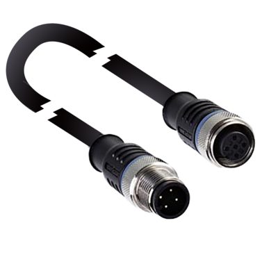
| Termination |
Connector plug M12, 4-pole, (A-coding) |
Mechanical data - Dimensions
| Length of sensor |
22 mm |
| Width of sensor |
106.3 mm |
| Height of sensor |
25 mm |
Ambient conditions
| Degree of protection |
IP65 IP67 IP69 |
| Ambient temperature |
-25 ... +70 °C |
| Storage and transport temperature |
-25 ... +85 °C |
| Relative humidity, maximum |
93 % |
| Note (Relative humidity) |
non-condensing non-icing |
| Resistance to vibrations |
10 … 55 Hz, amplitude 1 mm |
| Restistance to shock |
30 g / 11 ms |
| Protection class |
III |
| Permissible installation altitude above sea level, maximum |
2,000 m |
Ambient conditions - Insulation values
| Rated insulation voltage Ui |
32 VDC |
| Rated impulse withstand voltage Uimp |
0.8 kV |
| Overvoltage category |
III |
| Degree of pollution |
3 |
Electrical data
| Time to readiness, maximum |
5,000 ms |
| Switching frequency, maximum |
1 Hz |
Electrical data - AS Interface
| Rated operating voltage |
18 ... 31.6 VDC (Protection against polarity reversal) |
| AS-i Current consumption, maximum |
100 mA |
Electrical data - AS-Interface specification
| AS-i Specification |
Safety-Slave |
| AS-i Version |
V 3.0 |
| AS-i Profile |
S-0.B.F.E |
| AS-i, IO-Code |
0x0 |
| AS-i, ID-Code |
0xB |
| AS-i, ID-Code1 |
0xF |
| AS-i, ID-Code2 |
0xE |
| AS-i Input, Channel 1 |
Data bits DI 0 / DI 1 = dynamic code transmission |
| AS-i Input, Channel 2 |
Data bits DI 2 / DI 3 = dynamic code transmission |
| AS-i Outputs, DO 0 … DO 3 |
No Function |
| AS-i Parameter bits, P0 |
Number actuator 01-15 (binary) |
| AS-i Parameter bits, P1 |
Number actuator 01-15 (binary) |
| AS-i Parameter bits, P2 |
Number actuator 01-15 (binary) |
| AS-i Parameter bits, P3 |
Number actuator 01-15 (binary) |
| Note (AS-i Parameter bits) |
Set the parameter outputs to "1111" (0xF) FID: periphery error |
| AS-i Input module address |
0 |
| Note (AS-i Input module address) |
Preset to address 0, can be changed through AS-interface bus master or hand-held programming device |
Status indication
| Note (LED switching conditions display) |
(1) green/red LED (AS-i Duo LED):Supply voltage / communication error / slave address = 0 / periphery error detected / Tamper protection time active (2) yellow LED: device condition (enabling status) / hysteresis signal / device error |
Pin assignment
| PIN 1 |
AS-Interface + |
| PIN 2 |
n.c. (≤ 30 VDC) |
| PIN 3 |
AS-Interface - |
| PIN 4 |
n.c. (≤ 30 VDC) |
Scope of delivery
| Scope of delivery |
Actuator must be ordered separately. |
Accessory
| Recommendation (actuator) |
RST 36-1-AD01…15 |
Language filter
Datasheet
Operating instructions and Declaration of conformity
ANATEL certification
ECOLAB certification
AS interface safety at work certificate
TÜV certification
Info
SISTEMA-VDMA library
Download the latest version of Adobe Reader
Product picture (catalogue individual photo)

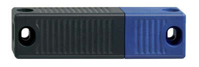
101213820 RST 36-1
- Actuation from side
- Simple flexible mounting and adjustment
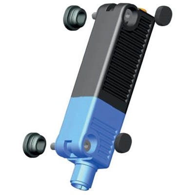
101213821 RST 36-1-R
- Actuation from side
- with latching magnet
- Simple flexible mounting and adjustment
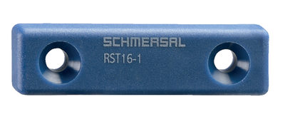
103038296 RST16-1-AD01
- Frontal actuation from assembly direction
- Flat design
- Mounting 2 x M5
- AS interface
103038297 RST16-1-AD02
- Frontal actuation from assembly direction
- Flat design
- Mounting 2 x M5
- AS interface
103038298 RST16-1-AD03
- Frontal actuation from assembly direction
- Flat design
- Mounting 2 x M5
- AS interface
103038299 RST16-1-AD04
- Frontal actuation from assembly direction
- Flat design
- Mounting 2 x M5
- AS interface
103038300 RST16-1-AD05
- Frontal actuation from assembly direction
- Flat design
- Mounting 2 x M5
- AS interface
103038301 RST16-1-AD06
- Frontal actuation from assembly direction
- Flat design
- Mounting 2 x M5
- AS interface
103038302 RST16-1-AD07
- Frontal actuation from assembly direction
- Flat design
- Mounting 2 x M5
- AS interface
103038303 RST16-1-AD08
- Frontal actuation from assembly direction
- Flat design
- Mounting 2 x M5
- AS interface
103038305 RST16-1-AD09
- Frontal actuation from assembly direction
- Flat design
- Mounting 2 x M5
- AS interface
103038306 RST16-1-AD10
- Frontal actuation from assembly direction
- Flat design
- Mounting 2 x M5
- AS interface
103038307 RST16-1-AD11
- Frontal actuation from assembly direction
- Flat design
- Mounting 2 x M5
- AS interface
103038308 RST16-1-AD12
- Frontal actuation from assembly direction
- Flat design
- Mounting 2 x M5
- AS interface
103038309 RST16-1-AD13
- Frontal actuation from assembly direction
- Flat design
- Mounting 2 x M5
- AS interface
103038310 RST16-1-AD14
- Frontal actuation from assembly direction
- Flat design
- Mounting 2 x M5
- AS interface
103038311 RST16-1-AD15
- Frontal actuation from assembly direction
- Flat design
- Mounting 2 x M5
- AS interface
103001551 RST 36-1-AD01
- Actuation from side
- Simple flexible mounting and adjustment
- AS interface
103001553 RST 36-1-AD02
- Actuation from side
- Simple flexible mounting and adjustment
- AS interface
103001554 RST 36-1-AD03
- Actuation from side
- Simple flexible mounting and adjustment
- AS interface
103001555 RST 36-1-AD04
- Actuation from side
- Simple flexible mounting and adjustment
- AS interface
103001556 RST 36-1-AD05
- Actuation from side
- Simple flexible mounting and adjustment
- AS interface
103001557 RST 36-1-AD06
- Actuation from side
- Simple flexible mounting and adjustment
- AS interface
103001558 RST 36-1-AD07
- Actuation from side
- Simple flexible mounting and adjustment
- AS interface
103001559 RST 36-1-AD08
- Actuation from side
- Simple flexible mounting and adjustment
- AS interface
103001560 RST 36-1-AD09
- Actuation from side
- Simple flexible mounting and adjustment
- AS interface
103001561 RST 36-1-AD10
- Actuation from side
- Simple flexible mounting and adjustment
- AS interface
103001562 RST 36-1-AD11
- Actuation from side
- Simple flexible mounting and adjustment
- AS interface
103001563 RST 36-1-AD12
- Actuation from side
- Simple flexible mounting and adjustment
- AS interface
103001564 RST 36-1-AD13
- Actuation from side
- Simple flexible mounting and adjustment
- AS interface
103001565 RST 36-1-AD14
- Actuation from side
- Simple flexible mounting and adjustment
- AS interface
103001566 RST 36-1-AD15
- Actuation from side
- Simple flexible mounting and adjustment
- AS interface
101215048 ACC RSS 36-SK
- to seal the mounting holes and as spacer (approx. 3 mm) to facilitate the cleaning below the mounting surface
- also suitable as tampering protection for the screw fixings
| EU Declaration of Conformity |  |
| Original | K.A. Schmersal GmbH & Co. KG Möddinghofe 30 42279 Wuppertal Germany Internet: www.schmersal.com |
| Declaration: | We hereby certify that the hereafter described components both in their basic design and construction conform to the applicable European Directives. |
| Name of the component: | RSS36-AS |
| Type: | See ordering code |
| Description of the component: | Non-contact safety sensor with integrated AS-i Safety at Work |
| Relevant Directives: | Machinery Directive | 2006/42/EC |
| RED-Directive | 2014/53/EU | |
| RoHS-Directive | 2011/65/EU |
| Applied standards: | EN 60947-5-3:2013 EN 300 330 V2.1.1:2017 EN ISO 14119:2013 EN ISO 13849-1:2015 EN 61508 parts 1-7:2010 |
| Notified body for Type Examination: | TÜV Rheinland Industrie Service GmbH Am Grauen Stein, 51105 Köln ID n°: 0035 |
| EC-Type Examination Certificate: | 01/205/5115.02/19 |
| Person authorised for the compilation of the technical documentation: | Oliver Wacker Möddinghofe 30 42279 Wuppertal |
| Place and date of issue: | Wuppertal, March 7, 2024 |
 |
| Authorised signature Philip Schmersal Managing Director |
| UK Declaration of Conformity | |
| Company: | K.A. Schmersal GmbH & Co. KG Möddinghofe 30 42279 Wuppertal Germany Internet: www.schmersal.com |
| Declaration: | We hereby, under sole responsibility, certify that the hereafter described components both in their basic design and construction conform to the relevant statutory requirements, regulations and designated standards of the United Kingdom. |
| Name of the component: | RSS36-AS |
| Type: | See ordering code |
| Description of the component: | Non-contact safety sensor with integrated AS-i Safety at Work |
| Relevant legislation: | Supply of Machinery (Safety) Regulations | 2008 |
| Radio Equipment Regulations | 2017 | |
| The Restriction of the Use of Certain Hazardous Substances in Electrical and Electronic Equipment Regulations | 2012 |
| Designated standards: | EN 60947-5-3:2013 EN 300 330 V2.1.1:2017 EN ISO 14119:2013 EN ISO 13849-1:2015 EN 61508 parts 1-7:2010 |
| Approved body for Type Examination: | TÜV Rheinland UK Ltd. 1011 Stratford Road Solihull, B90 4BN ID: 2571 |
| Type examination certificate: | 01/205U/5115.00/22 |
| UK-Importer / Person authorised for the compilation of the technical documentation: | Schmersal UK Ltd. Paul Kenney Unit 1, Sparrowhawk Close Enigma Business Park Malvern, Worcestershire, WR14 1GL |
| Place and date of issue: | Wuppertal, March 7, 2024 |
|
| Authorised signature Philip Schmersal Managing Director |
Schmersal Canada Ltd., 29 Centennial Road, Unit 1, Orangeville, Ontario L9W 1R1 Canada
The details and data referred to have been carefully checked. Images may diverge from original. Further technical data can be found in the manual. Technical amendments and errors possible.
Generated on: 2025-05-11, 7:14 p.m.
Recently viewed

RF-AZM200/201-N
RDLMWS
SET SL 300-2540