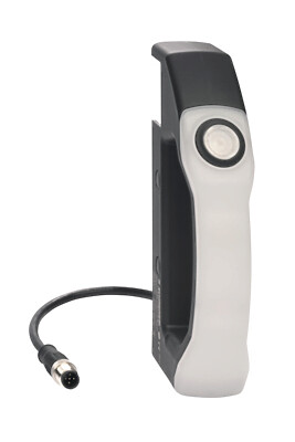
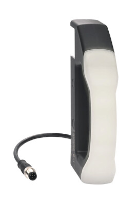
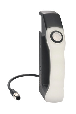
RSS260-SD-LSTM12-8-0,25M
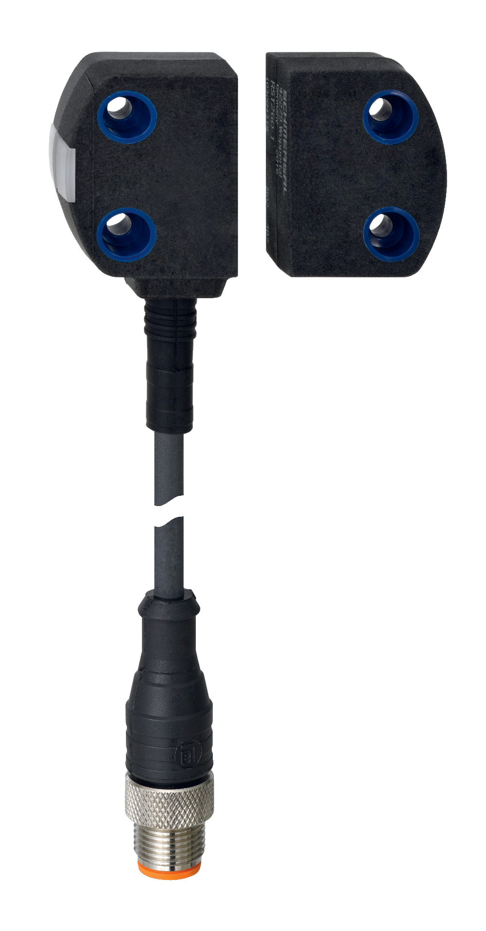
RSS260-SD-LSTM12-8-0,25M
| Product type description: RSS260-(1)-(2)-(3)-(4)-(5) |
| (1) | |
| without | Standard coding |
| I1 | Individual coding |
| I2 | Individual coding, multiple teaching |
| (2) | |
| D | With diagnostic output |
| SD | With serial diagnostic function 1) |
| (3) | |
| without | Standard version without feedback circuit monitoring EDM (External Device Monitoring) |
| F0 | EDM with automatic reset 1) |
| F1 | EDM with manual reset 1) |
| (4) | |
| without | Without EMERGENCY STOP |
| Q | Acknowledge input error with EMERGENCY STOP 1) |
| (5) | |
| without | Connecting cable (lenght in m) |
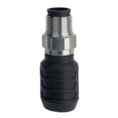
| ST | Connector plug M8, 8-pole |
| LSTM12-8-0,25M | Cable 0.25 m long with connector M12, 8-pole |
| LSTM8-8-0,1M | Cable 0.1 m long with connector M8, 8-pole |
| LSTM12-5-0.25M | Cable 0.25 m long with connector M12, 5-pole |
| (*) | |
| 1) | only for versions -ST, -LSTM12-8-0.25M and -LSTM8-8-0.1M |
- Universal coding with RFID technology
- Frontal and lateral actuation enabled
- Max. 31 sensors can be wired in series.
- serial diagnostic output
- Thermoplastic enclosure
- Simple mounting without additional angle
- RFID-technology for needs-based protection against tampering
Ordering data
| Product type description |
RSS260-SD-LSTM12-8-0,25M |
| Article number (order number) |
103025087 |
| EAN (European Article Number) |
4030661512167 |
| eCl@ss number, version 12.0 |
27-27-46-01 |
| eCl@ss number, version 11.0 |
27-27-24-03 |
| eCl@ss number, version 9.0 |
27-27-24-03 |
| ETIM number, version 7.0 |
EC001829 |
| ETIM number, version 6.0 |
EC001829 |
Approvals - Standards
| Certificates |
TÜV cULus FCC IC ANATEL |
General data
| Standards |
EN ISO 13849-1 EN IEC 60947-5-3 EN IEC 61508 |
| Coding |
Universal coding |
| Coding level according to EN ISO 14119 |
Low |
| Working principle |
RFID |
| Frequency band RFID |
125 kHz |
| Transmitter output RFID, maximum |
-6 dBm |
| Housing construction form |
Block |
| Installation conditions (mechanical) |
not flush |
| Sensor topology |
Sensor for series wiring |
| Housing material |
Plastic, thermoplastic, self-extinguishing |
| Active area |
Glass-fibre, thermoplastic |
| Reaction time, maximum |
100 ms |
| Duration of risk, maximum |
200 ms |
| Reaction time, switching off safety outputs via actuator, maximum |
100 ms |
| Gross weight |
121 g |
General data - Features
| Serial diagnostics |
Yes |
| Short circuit detection |
Yes |
| Cross-circuit detection |
Yes |
| Series-wiring |
Yes |
| Safety functions |
Yes |
| Cascadable |
Yes |
| Integral system diagnostics, status |
Yes |
| Number of LEDs |
3 |
| Number of poles |
8 |
| Number of fail-safe digital outputs |
2 |
| Number of series-wiring of sensors |
31 |
| Safety classification |
| Standards |
EN ISO 13849-1 EN IEC 61508 |
| Performance Level, up to |
e |
| Category |
4 |
| PFH value |
6.80 x 10⁻¹⁰ /h |
| PFD value |
1.20 x 10⁻⁴ |
| Safety Integrity Level (SIL), suitable for applications in |
3 |
| Mission time |
20 Year(s) |
Mechanical data
| Actuating panels |
lateral front side |
| Active area |
lateral front |
| Mounting |
A 20 mm screw length usually suffices to mount the sensor. When the mounting plates are used, we recommend 25 mm long screws. |
| Type of the fixing screws |
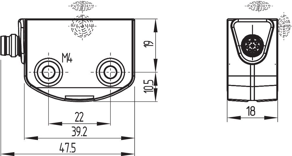
2x M4 |
| Tightening torque of the fixing screws, maximum |
0.8 Nm |
Mechanical data - Switching distances
| Typical switching distance, frontal |
12 mm |
| Typical switching distance, lateral |
9 mm |
| Assured switching distance "ON", frontal |
10 mm |
| Assured switching distance "OFF", frontal |
18 mm |
| Assured switching distance "ON", lateral |
6 mm |
| Assured switching distance "OFF", lateral |
15 mm |
| Note (Sao) |
The specifications of the safety switching distance Sao refer to a temperature range of |
| Note (switching distance) |
All switching distances in accordance EN IEC 60947-5-3 Axial misalignment, a horizontal and vertical misalignment of the safety sensor and the actuator are tolerated. The possible misalignment depends on the distance of the active surfaces of the sensor and the actuator. The sensor remains active within the tolerance range. |
| Hysteresis (Switching distance), maximum |
2 mm |
| Repeat accuracy R |
0.5 mm |
| Note (Repeat accuracy R) |
Axial offset: The long side allows for a maximum height misalignment (x) of sensor and actuator of 8 mm (e.g. mounting tolerance or due to guard door sagging). The axial misalignment (y) is max. ± 18 mm (see figure: Operating principle).Minimum clearance between two sensor systems 100 mm |
Mechanical data - Connection technique
| Note (length of the sensor chain) |
Cable length and cross-section change the voltage drop dependiing on the output current |
| Note (series-wiring) |
Unlimited number of devices, oberserve external line fusing, max. 31 devices in case of serial diagnostic SD |
| Termination |
Connector M12, 8-pole, A-coded |
Mechanical data - Dimensions
| Length of sensor |
29.5 mm |
| Width of sensor |
39.2 mm |
| Height of sensor |
18 mm |
Ambient conditions
| Degree of protection |
IP65 IP67 |
| Ambient temperature |
-28 ... +65 °C |
| Storage and transport temperature |
-28 ... +85 °C |
| Relative humidity, maximum |
93 % |
| Note (Relative humidity) |
non-condensing non-icing |
| Resistance to vibrations |
10 … 55 Hz, amplitude 1 mm |
| Restistance to shock |
30 g / 11 ms |
| Permissible installation altitude above sea level, maximum |
2,000 m |
Ambient conditions - Insulation values
| Rated insulation voltage Ui |
32 VDC |
| Rated impulse withstand voltage Uimp |
0.8 kV |
| Overvoltage category |
III |
| Degree of pollution |
3 |
Electrical data
| Operating voltage |
24 VDC -15 % / +10 % (stabilised PELV power supply) |
| Operating current, minimum |
0.5 mA |
| No-load supply current I0, typical |
35 mA |
| Rated operating voltage |
24 VDC |
| Operating current |
600 mA |
| Required rated short-circuit current |
100 A |
| Time to readiness, maximum |
2,000 ms |
| Switching frequency, maximum |
1 Hz |
| Electrical fuse rating, maximum |
2 A |
Electrical data - Safety digital inputs
| Designation, Safety inputs |
X1 and X2 |
| Current consumption of the safety inputs |
5 mA |
| Test pulse duration, maximum |
1 ms |
| Test pulse interval, minimum |
100 ms |
| Classification ZVEI CB24I, Sink |
C1 |
| Classification ZVEI CB24I, Source |
C1 C2 C3 |
Electrical data - Safety digital outputs
| Designation, Safety outputs |
Y1 and Y2 |
| Rated operating current (safety outputs) |
250 mA |
| Output current, (fail-safe output), maximum |
0.25 A |
| Design of control elements |
short-circuit proof, p-type |
| Voltage drop Ud, maximum |
1 V |
| Leakage current Ir, maximum |
0.5 mA |
| Voltage, Utilisation category DC-12 |
24 VDC |
| Current, Utilisation category DC-12 |
0.25 A |
| Voltage, Utilisation category DC-13 |
24 VDC |
| Current, Utilisation category DC-13 |
0.25 A |
| Test pulse interval, typical |
1000 ms |
| Test pulse duration, maximum |
1 ms |
| Classification ZVEI CB24I, Source |
C2 |
| Classification ZVEI CB24I, Sink |
C1 C2 |
Electrical data - Serial diagnostic SD
| Designation, Serial diagnostic SD |
OUT |
| Operation current |
150 mA |
| Design of control elements |
short-circuit proof |
| Wiring capacitance |
50 nF |
Electrical data - Electromagnetic compatibility (EMC)
| Interfering radiation |
IEC 61000-6-4 |
Status indication
| Note (LED switching conditions display) |
LED yellow: Operating condition LED green: Supply voltage LED red: Fault |
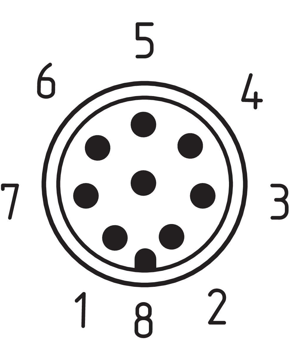
Pin assignment
| PIN 1 |
A1 Ue: White |
| PIN 2 |
X1 safety input 1: Brown |
| PIN 3 |
A2 GND: Green |
| PIN 4 |
Y1 safety output 1: Yellow |
| PIN 5 |
OUT serieller Diagnoseausgang: grau |
| PIN 6 |
X2 safety input 2: Pink |
| PIN 7 |
Y2 safety output 2: Blue |
| PIN 8 |
IN serial diagnostic input Pink |
Scope of delivery
| Scope of delivery |
Actuator must be ordered separately. |
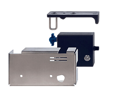
Accessory
| Recommendation (actuator) |
RST16-1 RST-U-2 RST260-1 |
| Recommended safety switchgear |
PROTECT PSC1 SRB-E-301ST SRB-E-201LC |
Note
| Note (General) |
Anforderungen an die Auswertung: Zweikanaliger Sicherheitseingang, geeignet für p-schaltende Sensoren mit Schließerfunktion. Die Funktionstests der Sensoren mit zyklischem Abschalten der Sensorausgänge für max. 1 ms müssen von der Auswertung toleriert werden. Eine Querschlusserkennung in der Auswertung ist nicht notwendig. |
Language filter
Datasheet
Operating instructions and Declaration of conformity
UL Certificate
FCC-Zertifikat
IC-Zertifikat
ANATEL certification
TÜV certification
Brochure
SISTEMA-VDMA library
Download the latest version of Adobe Reader
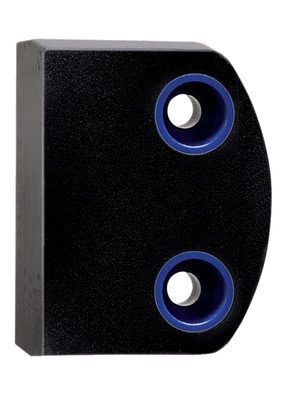
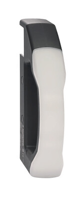
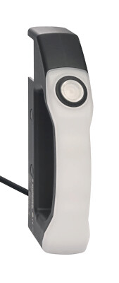
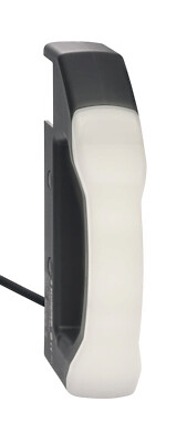
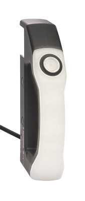
Product picture (catalogue individual photo)
Dimensional drawing basic component
Contact arrangement
Video ID: SD-Interface-Mr-Safety

Video ID: RSS-260-01
Basic function (Vimeo)

Video ID: RSS-260-02
Variable mounting options (Vimeo)
Video ID: RSS-260-03
Single device connection (Vimeo)
Video ID: RSS-260-04
Series connection with serial diagnostics (Vimeo)
Video ID: RSS-260-05
Cross-fault with controlled shut-down process (Vimeo)
Video ID: RSS-260-06
Tolerance to misalignment (Vimeo)
Video ID: RSS-260-07
Warning when actuator is in limit range (Vimeo)
Video ID: RSS-260-11
RST-16-1 actuator on flat contour safety guards (Vimeo)
Video ID: RSS-260-12
RST-U-2 actuator for confined spaces (Vimeo)
103004318 RST260-1
- Actuation from side
- Simple mounting
- Mounting 2 x M4
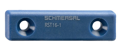
103004336 RST16-1
- Frontal actuation from assembly direction
- Flat design
- Mounting 2 x M5
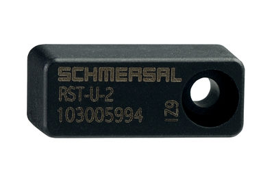
103005994 RST-U-2
- Frontal actuation from assembly direction
- small body
- Mounting 1 x M3 plus Twist protection
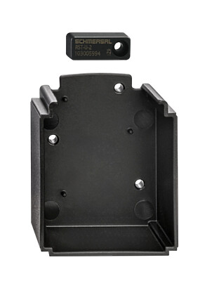
103055438 ACC-DHS-U1-INS-RST-U-2
- Actuator insert
- Incl. RST-U-2 actuator and attachment screw
- For use of the DHS-U1 in conjunction with safety sensor RSS260

103003639 A-K8P-M8-S-G-5M-BK-2-X-A-4
- Pre-wired cable
- 8-pole
103003640 A-K8P-M8-S-G-10M-BK-2-X-A-4
- Pre-wired cable
- 8-pole
103003642 A-K8P-M8-S-W-5M-BK-2-X-A-4
- Pre-wired cable
- 8-pole
103003638 A-K8P-M8-S-G-2M-BK-2-X-A-4
- Pre-wired cable
- 8-pole
103043263 A-K8P-M8-S-W-2M-BK-2-X-A-4 (V2)
- Pre-wired cable
- 8-pole
103043265 A-K8P-M8-S-W-10M-BK-2-X-A-4 (V2)
- Pre-wired cable
- 8-pole

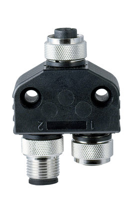
101209414 CSS-Y-A-8P
- Accessories for series-wiring with serial diagnostics
- The connector supplies the safety channels with operating voltage.
103008718 CSS-Y-A-8P-VA
- Accessories for series-wiring with serial diagnostics
- The connector supplies the safety channels with operating voltage.
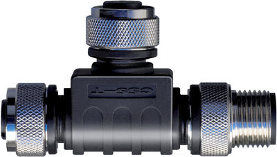
103009361 SD-Y-POWER
- Accessories for series-wiring with serial diagnostics
103009362 SD-Y-POWER VA
- Accessories for series-wiring with serial diagnostics
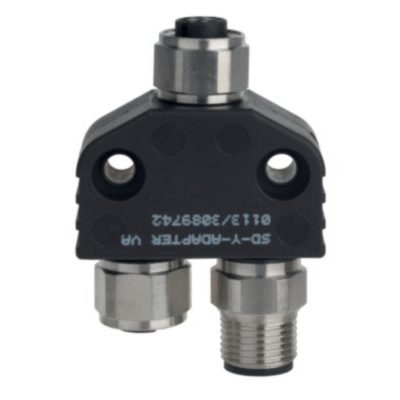
101190026 CSS-T
- Accessories for series-wiring with serial diagnostics
- for Sensors

101190025 CSS-T-A
- Accessories for series-wiring with serial diagnostics
- for CSS 34

101209416 CSS-Y-8P
- Accessories for series-wiring with serial diagnostics
103008717 CSS-Y-8P-VA
- Accessories for series-wiring with serial diagnostics
103053675 DHS-U1-BKWH
- Without electrical connection
- Door handle in an ergonomical design
- Can be combined with solenoid interlock AZM40 or safety sensor RSS260
- Can also be used without safety switchgear device
- For left or right hinged safety guards
103053688 DHS-U1-BKWH-L5-5.00-LT
- With illuminated pushbutton
- Connecting cable, 5-core, 5 m
- Protection class IP65 / IP67
- Machine status directly recognisable on the door handle
- Door handle in an ergonomical design
- Can be combined with solenoid interlock AZM40 or safety sensor RSS260
- Can also be used without safety switchgear device
- For left or right hinged safety guards
103053692 DHS-U1-BKWH-L5-5.00-RGB
- Connecting cable, 5-core, 5 m
- Degree of protection IP65 / IP67
- Machine status directly recognisable on the door handle
- With door handle lighting
- Door handle in an ergonomical design
- Can be combined with solenoid interlock AZM40 or safety sensor RSS260
- Can also be used without safety switchgear device
- For left or right hinged safety guards
103053689 DHS-U1-BKWH-L8-5.00-RGB-LT
- For left or right hinged safety guards
- With door handle lighting and illuminated push-button
- Connecting cable, 8-core, 5 m
- Protection class IP65 / IP67
- Machine status directly recognisable on the door handle
- Door handle in an ergonomical design
- Can be combined with solenoid interlock AZM40 or safety sensor RSS260
- Can also be used without safety switchgear device
103053676 DHS-U1-BKWH-LST5-0.25-LT
- With illuminated pushbutton
- Connecting cable with connector M12, 5-pole, 0.25 m
- Protection class IP65 / IP67
- Machine status directly recognisable on the door handle
- Door handle in an ergonomical design
- Can be combined with solenoid interlock AZM40 or safety sensor RSS260
- Can also be used without safety switchgear device
- For left or right hinged safety guards
103053691 DHS-U1-BKWH-LST5-0.25-RGB
- With door handle lighting
- Connecting cable with connector M12, 5-pole, 0.25 m
- Degree of protection IP65 / IP67
- Machine status directly recognisable on the door handle
- Door handle in an ergonomical design
- Can be combined with solenoid interlock AZM40 or safety sensor RSS260
- Can also be used without safety switchgear device
- For left or right hinged safety guards
103053677 DHS-U1-BKWH-LST8-0.25-RGB-LT
- With door handle lighting and illuminated push-button
- Connecting cable with connector M12, 8-pole, 0.25 m
- Protection class IP65 / IP67
- Machine status directly recognisable on the door handle
- Door handle in an ergonomical design
- Can be combined with solenoid interlock AZM40 or safety sensor RSS260
- Can also be used without safety switchgear device
- For left or right hinged safety guards
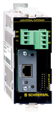
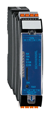
101209435 SD-I-U-CCL
- UNIVERSAL Gateway for the series-wiring of the diagnostic signals of safety
switchgear with integrated SD interface. - Comprehensive volumes of status and diagnostic data of the SD devices are transmitted to the control system through the field bus interface.
- Series-wiring of the diagnostic lines of max. 31 safety switchgear
- Series-wiring of different devices possible
- Reduced wiring efforts and costs as a result of the series-wiring of the safety channels and the diagnostic cables in the field.
- Automatic addressing of the safety switchgear in the SD interface
101209432 SD-I-U-DN
- UNIVERSAL Gateway for the series-wiring of the diagnostic signals of safety
switchgear with integrated SD interface. - Comprehensive volumes of status and diagnostic data of the SD devices are transmitted to the control system through the field bus interface.
- Series-wiring of the diagnostic lines of max. 31 safety switchgear
- Series-wiring of different devices possible
- Reduced wiring efforts and costs as a result of the series-wiring of the safety channels and the diagnostic cables in the field.
- Automatic addressing of the safety switchgear in the SD interface
103008132 SD-I-U-EC
- UNIVERSAL Gateway for the series-wiring of the diagnostic signals of safety
switchgear with integrated SD interface. - Comprehensive volumes of status and diagnostic data of the SD devices are transmitted to the control system through the field bus interface.
- Series-wiring of the diagnostic lines of max. 31 safety switchgear
- Series-wiring of different devices possible
- Reduced wiring efforts and costs as a result of the series-wiring of the safety channels and the diagnostic cables in the field.
- Automatic addressing of the safety switchgear in the SD interface
101210747 SD-I-U-EIP
- UNIVERSAL Gateway for the series-wiring of the diagnostic signals of safety
switchgear with integrated SD interface. - Comprehensive volumes of status and diagnostic data of the SD devices are transmitted to the control system through the field bus interface.
- Series-wiring of the diagnostic lines of max. 31 safety switchgear
- Series-wiring of different devices possible
- Reduced wiring efforts and costs as a result of the series-wiring of the safety channels and the diagnostic cables in the field.
- Automatic addressing of the safety switchgear in the SD interface
103051502 SDG-ETC-RJ-CC
- Serial diagnosis of up to 31 safety relays via Schmersal SD bus
- Automatic addressing of the connected SD bus participants
- Diagnostic and configuration interface for easy commissioning and maintenance of the system
- Extensive additional functions via integrated web server
- Long-term storage of log messages via SD card
- Conversion of status and diagnostics data to Ethernet-based fieldbus protocols
101218029 SD-I-U-MT
- UNIVERSAL Gateway for the series-wiring of the diagnostic signals of safety
switchgear with integrated SD interface. - Comprehensive volumes of status and diagnostic data of the SD devices are transmitted to the control system through the field bus interface.
- Series-wiring of the diagnostic lines of max. 31 safety switchgear
- Series-wiring of different devices possible
- Reduced wiring efforts and costs as a result of the series-wiring of the safety channels and the diagnostic cables in the field.
- Automatic addressing of the safety switchgear in the SD interface
103054152 SDG-PRN-RJ-CC
- Serial diagnosis of up to 31 safety relays via Schmersal SD bus
- Automatic addressing of the connected SD bus participants
- Diagnostic and configuration interface for easy commissioning and maintenance of the system
- Extensive additional functions via integrated web server
- Long-term storage of log messages via SD card
- Conversion of status and diagnostics data to Ethernet-based fieldbus protocols
101209434 SD-I-U-PN
- UNIVERSAL Gateway for the series-wiring of the diagnostic signals of safety
switchgear with integrated SD interface. - Comprehensive volumes of status and diagnostic data of the SD devices are transmitted to the control system through the field bus interface.
- Series-wiring of the diagnostic lines of max. 31 safety switchgear
- Series-wiring of different devices possible
- Reduced wiring efforts and costs as a result of the series-wiring of the safety channels and the diagnostic cables in the field.
- Automatic addressing of the safety switchgear in the SD interface
| EU Declaration of Conformity |  |
| Original | K.A. Schmersal GmbH & Co. KG Möddinghofe 30 42279 Wuppertal Germany Internet: www.schmersal.com |
| Declaration: | We hereby certify that the hereafter described components both in their basic design and construction conform to the applicable European Directives. |
| Name of the component: | RSS260 |
| Type: | See ordering code |
| Description of the component: | Non-contact safety sensor |
| Relevant Directives: | Machinery Directive | 2006/42/EC |
| RED-Directive | 2014/53/EU | |
| RoHS-Directive | 2011/65/EU |
| Applied standards: | EN 60947-5-3:2013 EN 300 330 V2.1.1:2017 EN ISO 14119:2013 EN ISO 13849-1:2023 EN 61508 parts 1-7:2010 |
| Notified body for Type Examination: | TÜV Rheinland Industrie Service GmbH Am Grauen Stein, 51105 Köln ID n°: 0035 |
| EC-Type Examination Certificate: | 01/205/5348.04/25 |
| Person authorised for the compilation of the technical documentation: | Oliver Wacker Möddinghofe 30 42279 Wuppertal |
| Place and date of issue: | Wuppertal, January 9, 2025 |
 |
| Authorised signature Philip Schmersal Managing Director |
| UK Declaration of Conformity | |
| Company: | K.A. Schmersal GmbH & Co. KG Möddinghofe 30 42279 Wuppertal Germany Internet: www.schmersal.com |
| Declaration: | We hereby, under sole responsibility, certify that the hereafter described components both in their basic design and construction conform to the relevant statutory requirements, regulations and designated standards of the United Kingdom. |
| Name of the component: | RSS260 |
| Type: | See ordering code |
| Description of the component: | Non-contact safety sensor |
| Relevant legislation: | Supply of Machinery (Safety) Regulations | 2008 |
| Radio Equipment Regulations | 2017 | |
| The Restriction of the Use of Certain Hazardous Substances in Electrical and Electronic Equipment Regulations | 2012 |
| Designated standards: | EN 60947-5-3:2013 EN 300 330 V2.1.1:2017 EN ISO 14119:2013 EN ISO 13849-1:2015 IEC 61508 parts 1-7:2010 |
| Approved body for Type Examination: | TÜV Rheinland UK Ltd. 1011 Stratford Road Solihull, B90 4BN ID: 2571 |
| Type examination certificate: | 01/205U/5348.00/22 |
| UK-Importer / Person authorised for the compilation of the technical documentation: | Schmersal UK Ltd. Paul Kenney Unit 1, Sparrowhawk Close Enigma Business Park Malvern, Worcestershire, WR14 1GL |
| Place and date of issue: | Wuppertal, November 2, 2022 |
|
| Authorised signature Philip Schmersal Managing Director |
Schmersal Ltd., Sparrowhawk Close, WR14 1GL Malvern
The details and data referred to have been carefully checked. Images may diverge from original. Further technical data can be found in the manual. Technical amendments and errors possible.
Generated on: 21/09/2025, 13:24
Recently viewed
SLC440AS-ER-0490-30
Z4S 236-11Z

EX-ZS 235-02Z-3D

KA-0975
BDF200-NHK-20-LMGN-LTYE-LTRD

SLC 420-E/R0170-50-RFB

SHGV-SR/GR