SFB-EIP-8M12-IOP
SFB-EIP-8M12-IOP
- Caja de distribución segura para EtherNet/IP con CIP Safety
- Para la conexión de hasta 8 dispositivos de seguridad
- Interruptor Dual Port integrado
- Protección IP66, IP67
Detalles de Pedidos
| Descripción del tipo de producto |
SFB-EIP-8M12-IOP |
| Número de artículo (Nº artículo) |
103015480 |
| EAN (European Article Number) |
4030661628691 |
| eCl@ss number, version 12.0 |
27-24-26-04 |
| eCl@ss number, version 11.0 |
27-24-26-04 |
| Número eCl@ss, versión 9.0 |
27-24-26-04 |
| ETIM number, version 7.0 |
EC001599 |
| ETIM number, version 6.0 |
EC001599 |
Aprobaciones - Normas
|
TÜV cULus UKCA |
Propiedades Globales
| Normas |
EN IEC 61131-1 EN IEC 61131-2 EN ISO 13849-1 EN IEC 60947-5-3 EN IEC 61508 |
| Material de la caja |
Plástico, Poliamida PA 6 GF |
| Material de la etiqueta de identificación |
Plástico, Poliamida PA |
| Material de la ventana |
Poliamida PACM 12 |
| Material del recubrimiento electrónico |
Poliuretano 2K PU |
| Peso bruto |
649 g |
Datos generales - Características
| Indicador integrado, general |
Sí |
Certificación de seguridad
| Normas |
EN ISO 13849-1 EN IEC 61508 |
Certificación de seguridad - Entradas de seguridad 2 canal
| Nivel de prestaciones (PL) hasta |
e |
| Categoría de control |
4 |
| Diagnostic Coverage (DC) Level |
99 % |
| Valor PHF |
1,10 x 10⁻⁹ /h |
| PFDavg |
9,60 x 10⁻⁵ |
| Safety Integrity Level (SIL), adecuado para aplicaciones en |
3 |
| Vida útil |
20 Año(s) |
| Tiempo de reacción, entrada de seguridad local ⇒ bus de campo, máximo |
20 ms |
| Nota |
La SFB cumple con las exigencias de un PDDB (interruptor de aproximación con comportamiento definido en condiciones de error) según EN 60947-5-3 en combinación con sensores magnéticos (2 contactos NC) hasta PLe / SIL 3. |
Certificación de seguridad - Entradas de seguridad 1 canal
| Nivel de prestaciones (PL) hasta |
d |
| Categoría de control |
2 |
| Diagnostic Coverage (DC) Level |
90 % |
| Valor PHF |
2,30 x 10⁻⁷ /h |
| PFDavg |
2,00 x 10⁻² |
| Safety Integrity Level (SIL), adecuado para aplicaciones en |
1 |
| Vida útil |
20 Año(s) |
| Tiempo de reacción, entrada de seguridad local ⇒ bus de campo, máximo |
20 ms |
| Intervalo de prueba para detección de errores |
10 s |
Certificación de seguridad - Salidas de seguridad 1 canal
| Nivel de prestaciones (PL) hasta |
d |
| Categoría de control |
3 |
| Diagnostic Coverage (DC) Level |
90 % |
| Valor PHF |
1,00 x 10⁻⁷ /h |
| PFDavg |
8,80 x 10⁻³ |
| Safety Integrity Level (SIL), adecuado para aplicaciones en |
2 |
| Vida útil |
20 Año(s) |
| Tiempo de reacción: bus de campo ⇒ salida de seguridad local, máximo |
50 ms |
Certificación de seguridad - Salidas de seguridad 2 canal
| Nivel de prestaciones (PL) hasta |
e |
| Categoría de control |
4 |
| Diagnostic Coverage (DC) Level |
99 % |
| Valor PHF |
1,20 x 10⁻⁹ /h |
| PFDavg |
1,10 x 10⁻⁴ |
| Safety Integrity Level (SIL), adecuado para aplicaciones en |
3 |
| Vida útil |
20 Año(s) |
| Tiempo de reacción: bus de campo ⇒ salida de seguridad local, máximo |
50 ms |
Datos mecánicos
| Montaje |
Tornillos |
| Ejecución de los tornillos de fijación |
2x M6 |
| Par de apriete de los tornillos de fijación, máximo |
3 Nm |
| Diseño de los tornillos de fijación, mirilla |
2x TX10 (Torx) |
| Par de apriete de los tornillos de fijación de la ventana, máximo |
0,6 Nm |
Datos mecánicos - Conexionado
| Conexión conector |
Receptáculo M12 /-conector |
| Conector, entrada/salida |
X0 - X7: M12, 8-polos, codificación A |
| Conector, E/S de potencia |
M12 POWER, 4-polos, codificación T |
| Conector, bus de campo |
M12, 4-polos, codificación D |
| Tightening torque of electrical connection, minimum |
0,8 Nm |
| Par de apriete de la conexión eléctrica, máximo |
1,5 Nm |
Datos mecánicos - Dimensiones
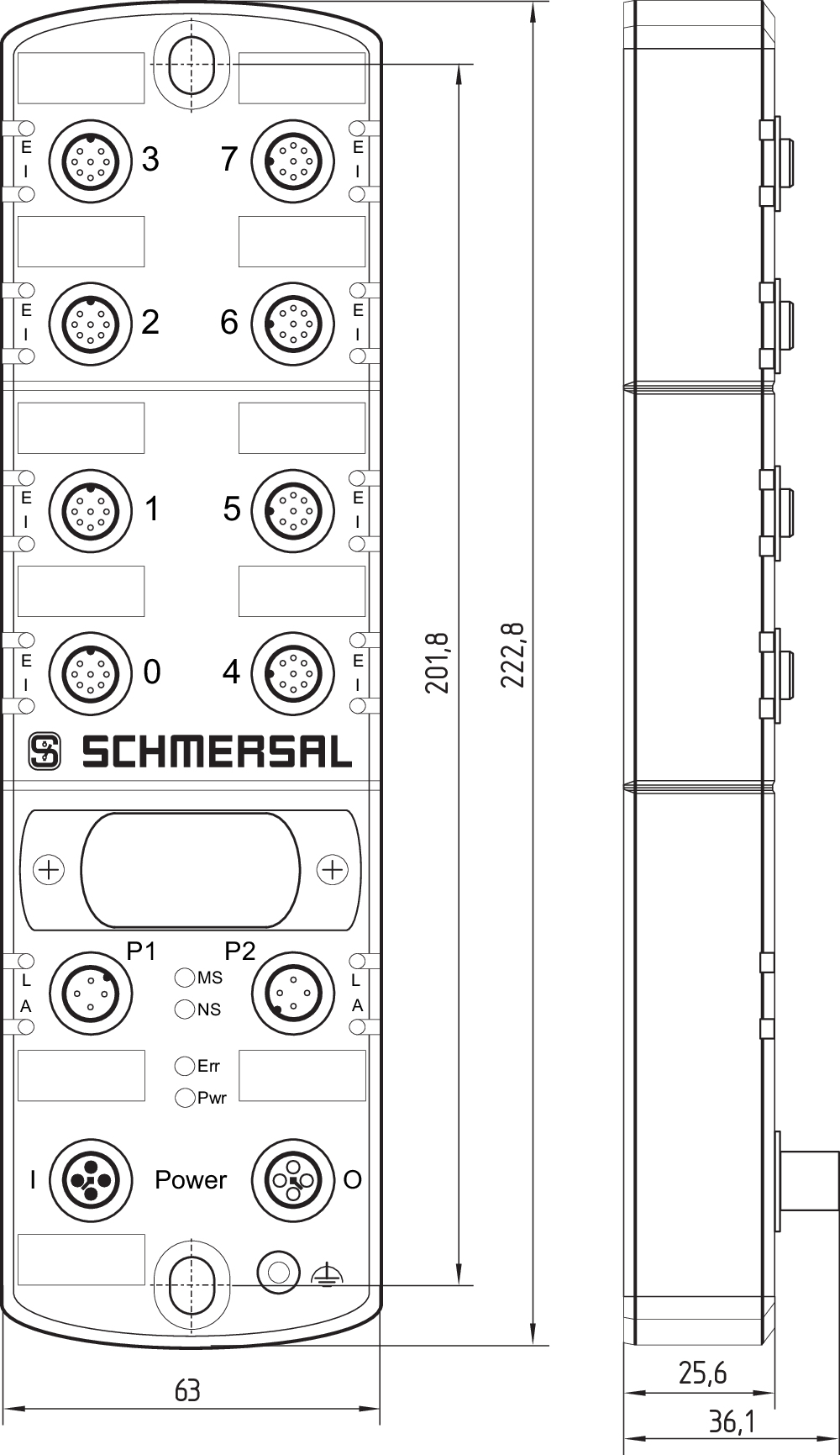
| Longitud |
222,8 mm |
| Anchura |
63 mm |
| Altura |
36,1 mm |
Condiciones ambientales
| Protección |
IP66 IP67 |
| Temperatura ambiente |
-25 ... +55 °C |
| Temperatura de almacén y de transporte |
-25 ... +70 °C |
| Humedad relativa, mínima |
10 % |
| Humedad relativa, máxima |
95 % |
| Nota (humedad relativa) |
sin condensación |
| Resistencia a vibraciones |
10 … 150 Hz, amplitud 0,35 mm / 5 g |
| Resistencia al impacto |
30 g / 11 ms |
| Grado de protección. |
III |
| Altura de montaje snm permitida, máximo |
2.000 m |
Condiciones ambientales - Valores de aislamiento
| Tensión de aislamiento nominal Ui |
32 VDC |
| Resistencia al impulso de sobretensión Uimp |
0,8 kV |
| Categoría de sobre-tensión |
III |
| Grado de polución |
3 |
Datos eléctricos
| Tensión operativa |
24 VDC -15 % / +10 % |
| Corriente operativa |
200 mA |
| Tensión nominal operativa |
24 VDC |
| Corriente nominal operativa |
10.000 mA |
| Nota (datos eléctricos, fusibles) |
Se necesita fusible externo ≤ 10A lento en el uso según UL 61010. |
| Retardo de disponibilidad, máxima |
12.000 ms |
| Device Watchdog Time |
12 ms |
| Reaction Time Safety Input, maximum |
20 ms |
| Reaction Time Safety Output, maximum |
50 ms |
Datos eléctricos - Protocolos de comunicación
| Protocolo de bus de campo |
EtherNet/IP / CIP Safety |
| Especificación del bus de campo |
V1.27 |
| Especificación de bus de campo seguro |
V2.22 |
| Propiedades del bus de campo |
Device Level Ring (DLR) |
| Ratio de transferencia |
100 Mbit/s Full Duplex |
| Direccionamiento |
Dynamic Host Configuration Protocol (DHCP) / BootP |
| Interruptor integrado |
Dual Port, 100 Mbit/s |
| Servicios de bus de campo |
LLDP |
| Interfaz de servicio |
WEB-Interface HTTP |
Electrical data - Device Ports
| Designación, conexiones de dispositivos |
X0 ... X7 |
| Longitud del cable, conexión del dispositivo |
30 m |
Electrical data - Power supply external devices
| Denominación, alimentación |
A1 and A2 |
| Tensión nominal operativa |
24 VDC |
| Corriente nominal operativa |
800 mA |
| Protección por fusible eléctrico interno |
1.5 A (Integrated automatic resettable fuse) |
Datos eléctricos - Entradas digitales seguras
| Denominación, entradas de seguridad |
X1 y X2 |
| Umbrales de conmutación |
−3 V … 5 V (Low) 13 V ... 30 V (High) |
| Corriente operativa a 24 V |
6 mA |
| Corriente residual permitida del control |
1 mA |
| Duración de impulso de prueba, mínima |
0,01 ms |
| Test pulse duration, maximum |
1 ms |
| Test pulse interval, minimum |
20 ms |
| Periodo de impulso de prueba, máxima |
120.000 ms |
| Clasificación ZVEI CB24I, depresión |
C1 |
| Clasificación ZVEI CB24I, fuente |
C1 C2 C3 |
Datos eléctricos - Salidas digitales seguras
| Denominación, salidas de seguridad |
DO |
| Versión |
protegidas contra cortocircuitos, tipo p |
| Caída de tensión Ud, máxima |
2 V |
| Corriente residual Ir, máxima |
0,5 mA |
| Tensión, categoría de utilización DC-12 |
24 VDC |
| Corriente, categoría de utilización DC-12 |
0,8 A |
| Tensión, categoría de utilización DC-13 |
24 VDC |
| Corriente, categoría de utilización DC-13 |
0,8 A |
| Nota, categoría de utilización DC-13 |
Inductive load, maximum 400 mH |
| Frecuencia de conmutación, máxima |
1 Hz |
| Test pulse duration, maximum |
1 ms |
| Periodo de impulso de prueba, mínima |
15 ms |
| Periodo de impulso de prueba, máxima |
500 ms |
| Clasificación ZVEI CB24I, fuente |
C1 |
| Clasificación ZVEI CB24I, depresión |
C1 |
Electrical data - Diagnostic inputs / FB-Interface
| Designación, entradas de diagnóstico / interfaz FB |
DI |
| Umbrales de conmutación |
−3 V … 5 V (Low) 15 V … 30 V (High) |
| Corriente operativa a 24V |
12 mA |
| Filtro anti-rebotes de entrada |
10 ms |
| Velocidad de transferencia de datos Interfaz FB |
19,2 kBaud |
Datos eléctricos - Salida por pulsos
| Denominación, salidas de impulsos |
Y1 and Y2 |
| Ejecución de los elementos de conmutación |
protegidas contra cortocircuitos, tipo p |
| Caída de tensión Ud, máxima |
1 V |
| Corriente residual Ir, máxima |
0,5 mA |
| Tensión, categoría de utilización DC-12 |
24 VDC |
| Y1 Corriente nominal de funcionamiento a 24 V |
15 mA |
| Y2 Corriente nominal de funcionamiento a 24 V |
10 mA |
| Y2 Corriente nominal de funcionamiento a 0 V |
30 mA |
| Periodo de impulso de prueba, típico |
500 ms |
| Duración de impulso de prueba, máxima |
1 ms |
| Clasificación ZVEI CB24I, depresión |
C1 |
| Clasificación ZVEI CB24I, fuente |
C1 |
Indicación de estado - LED 01
| Estados LED |
LED de error conexión de equipo |
| Posición LED |
E: 0 ... 7 |
| Color del LED |
verde/rojo |
Indicación de estado - LED 02
| Estados LED |
LED de entrada conexión de equipo |
| Posición LED |
I: 0 ... 7 |
| Color del LED |
amarillo |
Indicación de estado - LED 03
| Estados LED |
LED de enlace puerto Ethernet |
| Posición LED |
L: P1 + P2 |
| Color del LED |
verde |
Indicación de estado - LED 04
| Estados LED |
LED de actividad puerto Ethernet |
| Posición LED |
A: P1 + P2 |
| Color del LED |
amarillo |
Indicación de estado - LED 05
| Estados LED |
Module status LED |
| Posición LED |
"MS": Module |
| Color del LED |
verde/rojo |
Indicación de estado - LED 06
| Estados LED |
Network Status LED |
| Posición LED |
"NS": Módulo |
| Color del LED |
verde/rojo |
Indicación de estado - LED 07
| Estados LED |
LED de error de la caja de distribución |
| Posición LED |
"Err": Módulo |
| Color del LED |
verde/rojo |
Indicación de estado - LED 08
| Estados LED |
Power-LED caja de distribución pasiva |
| Posición LED |
"Pwr": Módulo |
| Color del LED |
verde |
Otros datos
| Nota (aplicaciones) |
Caja de distribución segura, con E/S descentralizadas |
Filtro de idiomas
Ficha técnica
Manual de instrucciones y declaración de conformidad
manual del sistema
Certificado del protocolo de pruebas
Certificado UL
Certificado UKCA
Archivos de descripción de los equipos
Información al cliente
Folleto
SISTEMA-VDMA Biblioteca/Library
Descargar la versión actual de Adobe Reader
Foto de producto (foto individual de catálogo)
Dibujo dimensional Componente básico
| EU Declaration of Conformity |  |
| Original | K.A. Schmersal GmbH & Co. KG Möddinghofe 30 42279 Wuppertal Germany Internet: www.schmersal.com |
| Declaration: | We hereby certify that the hereafter described components both in their basic design and construction conform to the applicable European Directives. |
| Name of the component: | SFB-EIP |
| Type: | See ordering code |
| Description of the component: | Safety fieldbox (IO module with fieldbox interface) |
| Relevant Directives: | Machinery Directive | 2006/42/EC |
| EMC-Directive | 2014/30/EU | |
| RoHS-Directive | 2011/65/EU |
| Applied standards: | EN 61131-2:2007 EN 60947-5-3:2013 EN ISO 13849-1:2015 IEC 61508 parts 1-7:2010 |
| Notified body for Type Examination: | TÜV Rheinland Industrie Service GmbH Am Grauen Stein, 51105 Köln ID n°: 0035 |
| EC-Type Examination Certificate: | 01/205/5878.03/23 |
| Person authorised for the compilation of the technical documentation: | Oliver Wacker Möddinghofe 30 42279 Wuppertal |
| Place and date of issue: | Wuppertal, June 5, 2023 |
 |
| Authorised signature Philip Schmersal Managing Director |
| UK Declaration of Conformity |  |
| Company: | K.A. Schmersal GmbH & Co. KG Möddinghofe 30 42279 Wuppertal Germany Internet: www.schmersal.com |
| Declaration: | We hereby, under sole responsibility, certify that the hereafter described components both in their basic design and construction conform to the relevant statutory requirements, regulations and designated standards of the United Kingdom. |
| Name of the component: | SFB-PN-IRT SFB-EIP |
| Type: | See ordering code |
| Description of the component: | Safety fieldbox (IO module with fieldbox interface) |
| Relevant legislation: | Supply of Machinery (Safety) Regulations | 2008 |
| Electromagnetic Compatibility Regulations | 2016 | |
| The Restriction of the Use of Certain Hazardous Substances in Electrical and Electronic Equipment Regulations | 2012 |
| Designated standards: | EN 61131-2:2007 EN 60947-5-3:2013 EN ISO 13849-1:2015 EN 61508 parts 1-7:2010 |
| Approved body for Type Examination: | TÜV Rheinland UK Ltd. 1011 Stratford Road Solihull, B90 4BN ID: 2571 |
| Type examination certificate: | 01/205U/5878.01/23 |
| UK-Importer / Person authorised for the compilation of the technical documentation: | Schmersal UK Ltd. Paul Kenney Unit 1, Sparrowhawk Close Enigma Business Park Malvern, Worcestershire, WR14 1GL |
| Place and date of issue: | Wuppertal, October 16, 2023 |
 |
| Authorised signature Philip Schmersal Managing Director |
Schmersal Ibérica, S.L., Rambla P. Catalanes, Nº 12, 08800 Vilanova i la Geltrú
Los datos e información anteriores se han verificado cuidadosamente. Las imágenes pueden diferir del original. Se pueden encontrar más datos técnicos en los manuales de instrucciones. Sujeto a cambios técnicos y errores.
Generado a 3/8/2025 20:20
.png?id=3f3339435fb0327df6974792fc349718)


