SRB-E-301MC
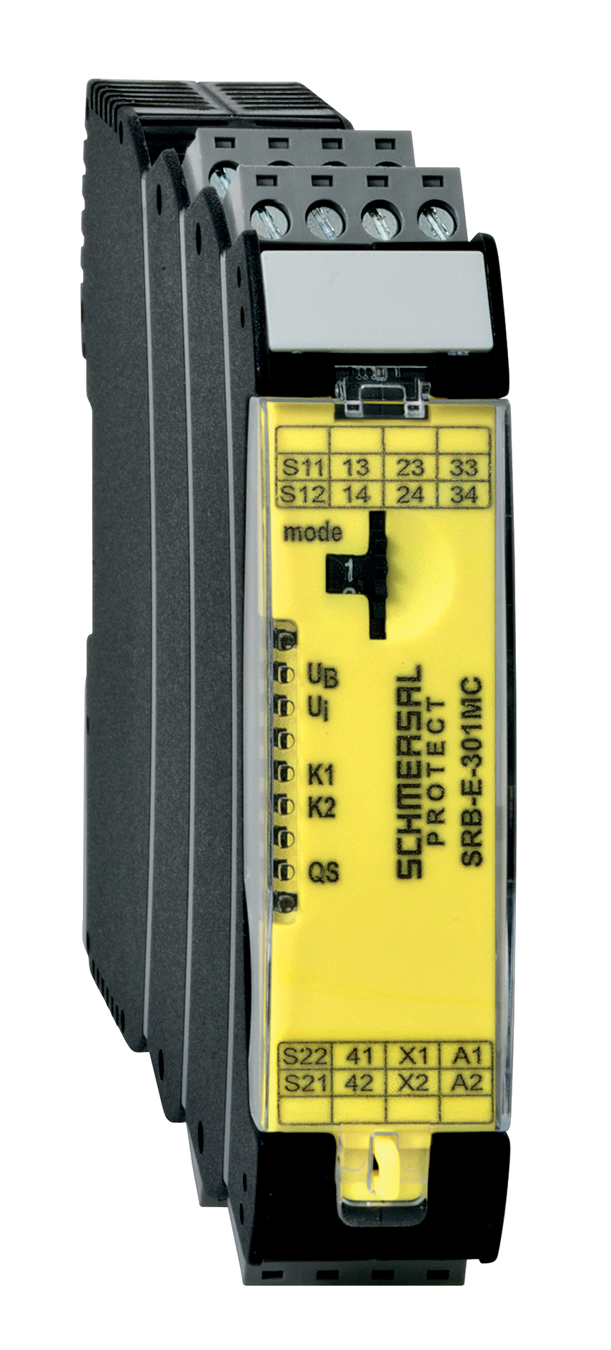
SRB-E-301MC
| Product type description: SRB-E-301MC-(1)(2) |
| Signalling contact 41/42, NC contacts in parallel | |
| 20 | Signalling contact 41/42, normally closed contacts in series |
| (2) | |
| Plug-in screw clamps: single wire (rigid) or fine wire (flexible): 0.2 … 2.5 mm²; fine wire with ferrule: 0.25 … 2.5 mm² | |
| CC | Plug-in cage clamps: single wire (rigid) or fine wire (flexible): 0.2 … 1.5 mm²; fine wire with ferrule: 0.25 … 1.5 mm² |
- 1 Contacto de señalización
- Terminales con tornillo enchufables con codificación
- Adecuado para aplicaciones hasta Cat. 4 / PL e y hasta SIL 3
- Evaluación de señales en 1 o 2 canales
- Monitorización de arranque / circuito de realimentación
- Detección de cortocircuitos entre hilos opcional
- 3 contactos de seguridad de la categoría Stop 0
Detalles de Pedidos
| Nota (disponibilidad) |
No más disponible! |
| Descripción del tipo de producto |
SRB-E-301MC |
| EAN (European Article Number) |
4030661508696 |
Propiedades Globales
| Normas |
EN IEC 62061 EN ISO 13849-1 EN IEC 60947-5-1 EN IEC 60947-5-3 EN IEC 60947-5-5 EN IEC 61508 EN IEC 60204-1 EN IEC 60947-1 |
| Estrés climático |
EN 60068-2-78 |
| Material de la caja |
Plástico reforzado con fibra de vidrio, ventilador |
| Peso bruto |
175 g |
Datos generales - Características
| Fusible electrónico |
Sí |
| Detección de roturas de cable |
Sí |
| Detección de cortocircuitos entre hilos |
Sí |
| Terminales enchufables |
Sí |
| Entrada de inicio/arranque |
Sí |
| Circuito de realimentación |
Sí |
| Función de rearme/rearranque automático |
Sí |
| Detección de cortocircuito a tierra |
Sí |
| Indicador integrado, estado |
Sí |
| Cantidad de contactos auxiliares |
1 |
| Cantidad de LED's |
5 |
| Cantidad de contactos NC |
2 |
| Cantidad de contactos de seguridad, STOP 0 |
3 |
Certificación de seguridad
| Normas |
EN ISO 13849-1 EN IEC 62061 EN IEC 61508 |
| Categoría de parada: Stop |
0 |
Certificación de seguridad - Salidas de relé
| Nivel de prestaciones (PL) hasta |
e |
| Categoría |
4 |
| Diagnostic Coverage (DC) Level |
> 99 % |
| Valor PHF |
6,00 x 10⁻⁹ /h |
| Valor de PFD |
4,00 x 10⁻⁵ |
| Safety Integrity Level (SIL), adecuado para aplicaciones en |
3 |
| Vida útil |
20 Año(s) |
| Common Cause Failure (CCF), mínimo |
65 |
Datos mecánicos
| Vida mecánica, mínima |
10.000.000 Maniobras |
| Montaje |
Sujeción rápida para carriles normalizados según IEC 60715 |
Datos mecánicos - Conexionado
| Designaciones de los terminales |
IEC 60947-1 |
| Conexión conector |
rígido o flexible Terminales con tornillo, enchufables |
| Sección del cable, mínima |
0,25 mm² |
| Sección del cable, máxima |
2,5 mm² |
| Par de apriete de los bornes |
0,5 Nm |
Datos mecánicos - Dimensiones
| Anchura |
22,5 mm |
| Altura |
98 mm |
| Profundidad |
115 mm |
Condiciones ambientales
| Grado de protección de la carcasa |
IP40 |
| Tipo de protección del lugar de instalación |
IP54 |
| Grado de protección de los terminales y/o conexiones |
IP20 |
| Temperatura ambiente |
-25 ... +60 °C |
| Temperatura de almacén y de transporte |
-40 ... +85 °C |
| Resistencia a vibraciones |
10 ... 55 Hz, amplitud 0,35 mm |
| Resistencia al impacto |
30 g / 11 ms |
Condiciones ambientales - Valores de aislamiento
| Resistencia al impulso de sobretensión Uimp |
4 kV |
| Categoría de sobre-tensión |
III |
| Grado de polución |
2 |
Datos eléctricos
| Gama de frecuencias |
50 Hz 60 Hz |
| Tensión operativa |
24 VAC -15 % / +10 % |
| Rizada residual |
10 % |
| Tensión nominal operativa |
24 VAC |
| Tensión nominal operativa |
24 VDC |
| Tensión de dimensionamiento de alimentación de control con 50 Hz c.a., mínima |
20,4 VAC |
| Tensión de dimensionamiento de alimentación de control con 50 Hz c.a., máxima |
26,4 VAC |
| Tensión de dimensionamiento de alimentación de control con 60 Hz c.a., mínima |
20,4 VAC |
| Tensión de dimensionamiento de alimentación de control con 60 Hz c.a., máxima |
26,4 VAC |
| Tensión de dimensionamiento de alimentación de control con c.c., mínima |
20,4 VDC |
| Tensión de dimensionamiento de alimentación de control con c.c., máxima |
28,8 VDC |
| Consumo de potencia eléctrica |
2,9 W |
| Consumo de potencia eléctrica |
5 VA |
| Resistencia de los contactos, máxima |
0,1 Ω |
| Nota (resistencia de los contactos) |
en estado nuevo |
| Retardo de desconexión en fallo de alimentación, típico |
80 ms |
| Retardo de desconexión en "Paro de Emergencia", típico |
20 ms |
| Retardo tras señal de inicio/arranque automático, típico |
100 ms |
| Retardo de inicio/arranque con “Pulsador Reset”, típico |
20 ms |
| Frecuencia de conmutación, máxima |
0,3 Hz |
| Material de los contactos, eléctricos |
Ag-Ni, autolimpiante, guiado monitorizado |
Datos eléctricos - Salidas de relé seguras
| Tensión, categoría de utilización AC-15 |
230 VAC |
| Corriente, categoría de utilización AC-15 |
4 A |
| Tensión, categoría de utilización DC-13 |
24 VDC |
| Corriente, categoría de utilización DC-13 |
4 A |
| Capacidad de conmutación, mínima |
10 VDC |
| Capacidad de conmutación, mínima |
10 mA |
| Capacidad de conmutación, máxima |
250 VAC |
| Capacidad de conmutación, máxima |
6 A |
Datos eléctricos - Entradas digitales
| Resistencia total de circuito, máxima |
40 Ω |
Datos eléctricos - Salidas de relés (Contactos auxiliares)
| Capacidad de conmutación, máxima |
24 VDC |
| Capacidad de conmutación, máxima |
1 A |
Datos eléctricos - Compatibilidad electromagnética (CEM)
| Resistencia al ruido eléctrico |
Directiva sobre compatibilidad electromagnética CEM |
Indicación de estado
| Estados de función mostrados |
Posición de los relés K2 Posición de ls relés K1 Tensión de servicio interna Ui UB: Tensión de alimentación disponible |
Otros datos
| Nota (aplicaciones) |
Sensor de seguridad Resguardo de seguridad Resguardo de seguridad, pivotante Pulsador de Paro de Emergencia Interruptor de Paro de Emergencia por tracción de cable Cortina óptica de seguridad Barreras ópticas de Seguridad |
Filtro de idiomas
Ficha técnica
Manual de instrucciones y declaración de conformidad
Declaración de conformidad UKCA
Folleto
SISTEMA-VDMA Biblioteca/Library
Descargar la versión actual de Adobe Reader
Foto de producto (foto individual de catálogo)
Video ID: Mr-Safety-SRB-E
(Vimeo)

Contenido
- 1 About this document
- 1.1 Function
- 1.2 Target group of the operating instructions: authorised qualified personnel
- 1.3 Explanation of the symbols used
- 1.4 Appropriate use
- 1.5 General safety instructions
- 1.6 Warning about misuse
- 1.7 Exclusion of liability
- 2 Product description
- 2.1 Ordering code
- 2.2 Special versions
- 2.3 Purpose
- 2.4 Technical Data
- 2.5 Derating / electrical lifespan of safety contacts
- 3 Mounting
- 3.1 General mounting instructions
- 3.2 Dimensions
- 4 Electrical connection
- 4.1 General information for electrical connection
- 4.2 Coding of connecting terminals
- 4.3 Pin configuration and LED displays
- 4.4 Wiring examples and configuration
- 4.5 Start configuration
- 4.5.1 External reset button
- 4.5.2 Feedback circuit / Automatic start
- 4.6 Sensor configuration
- 5 Settings
- 5.1 Adjustable applications
- 5.2 Changing setting or application
- 6 Diagnostic
- 7 Set-up and maintenance
- 7.1 Functional testing
- 7.2 Behaviour in the case of faults
- 7.3 Setting report
- 7.4 Maintenance
- 8 Disassembly and disposal
- 8.1 Disassembly
- 8.2 Disposal
1 About this document
1.1 Function
This document provides all the information you need for the mounting, set-up and commissioning to ensure the safe operation and disassembly of the switchgear. The operating instructions must be available in a legible condition and a complete version in the vicinity of the device.
1.2 Target group of the operating instructions: authorised qualified personnel
All operations described in the operating instructions manual must be carried out by trained specialist personnel, authorised by the plant operator only.
Please make sure that you have read and understood these operating instructions and that you know all applicable legislations regarding occupational safety and accident prevention prior to installation and putting the component into operation.
The machine builder must carefully select the harmonised standards to be complied with as well as other technical specifications for the selection, mounting and integration of the components.
1.3 Explanation of the symbols used
- Information, hint, note: This symbol is used for identifying useful additional information.
- Caution: Failure to comply with this warning notice could lead to failures or malfunctions.
Warning: Failure to comply with this warning notice could lead to physical injury and/or damage to the machine.
1.4 Appropriate use
The Schmersal range of products is not intended for private consumers.
The products described in these operating instructions are developed to execute safety-related functions as part of an entire plant or machine. It is the responsibility of the manufacturer of a machine or plant to ensure the correct functionality of the entire machine or plant.
The safety-monitoring module must be exclusively used in accordance with the versions listed below or for the applications authorised by the manufacturer. Detailed information regarding the range of applications can be found in the chapter "Product description".
1.5 General safety instructions
The user must observe the safety instructions in this operating instructions manual, the country specific installation standards as well as all prevailing safety regulations and accident prevention rules.
- Further technical information can be found in the Schmersal catalogues or in the online catalogue on the Internet: products.schmersal.com.
The information contained in this operating instructions manual is provided without liability and is subject to technical modifications.
There are no residual risks, provided that the safety instructions as well as the instructions regarding mounting, commissioning, operation and maintenance are observed.
1.6 Warning about misuse
- In case of inadequate or improper use or manipulations of the component, personal hazards or damage to machinery or plant components cannot be excluded.
1.7 Exclusion of liability
We shall accept no liability for damages and malfunctions resulting from defective mounting or failure to comply with the operating instructions manual. The manufacturer shall accept no liability for damages resulting from the use of unauthorised spare parts or accessories.
For safety reasons, invasive work on the device as well as arbitrary repairs, conversions and modifications to the device are strictly forbidden, the manufacturer shall accept no liability for damages resulting from such invasive work, arbitrary repairs, conversions and/or modifications to the device.
2 Product description
2.1 Ordering code
| Product type description: SRB-E-301MC-(1)(2) |
| Signalling contact 41/42, NC contacts in parallel | |
| 20 | Signalling contact 41/42, normally closed contacts in series |
| (2) | |
| Plug-in screw clamps: single wire (rigid) or fine wire (flexible): 0.2 … 2.5 mm²; fine wire with ferrule: 0.25 … 2.5 mm² | |
| CC | Plug-in cage clamps: single wire (rigid) or fine wire (flexible): 0.2 … 1.5 mm²; fine wire with ferrule: 0.25 … 1.5 mm² |
- Only if the action described in these operating instructions is carried out correctly will the safety function be safeguarded, including compliance with the Machinery Directive.
2.2 Special versions
For special versions, which are not listed in the ordering code, these specifications apply accordingly, provided that they correspond to the standard version.
2.3 Purpose
The safety relay modules for integration in safety circuits are designed for fitting in control cabinets. They are used for the safe evaluation of the signals of positive break position switches or safety sensors for safety functions on sliding, hinged and removable safety guards as well as emergency stop control devices, safety solenoid switches and AOPDs.
The safety function is defined as deactivating outputs 13/14, 23/24, 33/34 when inputs S12 and/or S22 are opened. Taking account of a PFH value assessment, the safety-relevant current paths meet the following requirements (see also chapter 2.6 “Safety classification”):
- Category 4 / PL e to DIN EN ISO 13849-1
- SIL 3 to IEC 61508 and DIN EN 62061
- The safety relay module is to be operated in an area in which access by personnel is restricted.
All applications for 1 or 2 channel fail-safe signal evaluation for the following guard systems:
• Guard door monitoring in accordance with EN ISO 14119
• Positive-break position switches in accordance with EN 60947-5-1
• Safety sensors in accordance with EN 60947-5-3
• Emergency-stop command devices in accordance with EN ISO 13850 and EN 60947-5-5
• Safety magnetic switches in accordance with EN 60947-5-3
• Safety light grids and barriers in accordance with EN 61496
To determine the Performance Level (PL) to EN ISO 13849-1 of the entire safety function (e.g. sensor, logic, actuator), an assessment of all relevant components is required.
- The entire concept of the control system, in which the safety component is integrated, must be validated to the relevant standards.
2.4 Technical Data
- The data specified in this manual are applicable when the component is operated with rated operating voltage Ue ±0%.
- Air clearances and creepage distances of the safety contacts
The safety contacts comply with the requirements for basic insulation.
Note about the safety classification
The PFH value of 6.0 × 10⁻⁹/h applies to the combinations of contact load (current through enabling contacts) and number of switching cycles (nop/y). At 365 operating days per year and a 24-hours operation, this results in the below-mentioned switching cycle times (tcycle) for the relay contacts. Diverging applications upon request.
| Contact load | nop/y | tcycle |
|---|---|---|
| 20 % | 880,000 | 0.6 min |
| 40 % | 330,000 | 1.6 min |
| 60 % | 110,000 | 5.0 min |
| 80 % | 44,000 | 12.0 min |
| 100 % | 17,600 | 30.0 min |
Propiedades Globales
| Normas |
EN IEC 62061 EN ISO 13849-1 EN IEC 60947-5-1 EN IEC 60947-5-3 EN IEC 60947-5-5 EN IEC 61508 EN IEC 60204-1 EN IEC 60947-1 |
| Estrés climático |
EN 60068-2-78 |
| Material de la caja |
Plástico reforzado con fibra de vidrio, ventilador |
| Peso bruto |
175 g |
Datos generales - Características
| Fusible electrónico |
Sí |
| Detección de roturas de cable |
Sí |
| Detección de cortocircuitos entre hilos |
Sí |
| Terminales enchufables |
Sí |
| Entrada de inicio/arranque |
Sí |
| Circuito de realimentación |
Sí |
| Función de rearme/rearranque automático |
Sí |
| Detección de cortocircuito a tierra |
Sí |
| Indicador integrado, estado |
Sí |
| Cantidad de contactos auxiliares |
1 |
| Cantidad de LED's |
5 |
| Cantidad de contactos NC |
2 |
| Cantidad de contactos de seguridad, STOP 0 |
3 |
Certificación de seguridad
| Normas |
EN ISO 13849-1 EN IEC 62061 EN IEC 61508 |
| Categoría de parada: Stop |
0 |
Certificación de seguridad - Salidas de relé
| Nivel de prestaciones (PL) hasta |
e |
| Categoría |
4 |
| Diagnostic Coverage (DC) Level |
> 99 % |
| Valor PHF |
6,00 x 10⁻⁹ /h |
| Valor de PFD |
4,00 x 10⁻⁵ |
| Safety Integrity Level (SIL), adecuado para aplicaciones en |
3 |
| Vida útil |
20 Año(s) |
| Common Cause Failure (CCF), mínimo |
65 |
Datos mecánicos
| Vida mecánica, mínima |
10.000.000 Maniobras |
| Montaje |
Sujeción rápida para carriles normalizados según IEC 60715 |
Datos mecánicos - Conexionado
| Designaciones de los terminales |
IEC 60947-1 |
| Conexión conector |
rígido o flexible Terminales con tornillo, enchufables |
| Sección del cable, mínima |
0,25 mm² |
| Sección del cable, máxima |
2,5 mm² |
| Par de apriete de los bornes |
0,5 Nm |
Datos mecánicos - Dimensiones
| Anchura |
22,5 mm |
| Altura |
98 mm |
| Profundidad |
115 mm |
Condiciones ambientales
| Grado de protección de la carcasa |
IP40 |
| Tipo de protección del lugar de instalación |
IP54 |
| Grado de protección de los terminales y/o conexiones |
IP20 |
| Temperatura ambiente |
-25 ... +60 °C |
| Temperatura de almacén y de transporte |
-40 ... +85 °C |
| Resistencia a vibraciones |
10 ... 55 Hz, amplitud 0,35 mm |
| Resistencia al impacto |
30 g / 11 ms |
Condiciones ambientales - Valores de aislamiento
| Resistencia al impulso de sobretensión Uimp |
4 kV |
| Categoría de sobre-tensión |
III |
| Grado de polución |
2 |
Datos eléctricos
| Gama de frecuencias |
50 Hz 60 Hz |
| Tensión operativa |
24 VAC -15 % / +10 % |
| Rizada residual |
10 % |
| Tensión nominal operativa |
24 VAC |
| Tensión nominal operativa |
24 VDC |
| Tensión de dimensionamiento de alimentación de control con 50 Hz c.a., mínima |
20,4 VAC |
| Tensión de dimensionamiento de alimentación de control con 50 Hz c.a., máxima |
26,4 VAC |
| Tensión de dimensionamiento de alimentación de control con 60 Hz c.a., mínima |
20,4 VAC |
| Tensión de dimensionamiento de alimentación de control con 60 Hz c.a., máxima |
26,4 VAC |
| Tensión de dimensionamiento de alimentación de control con c.c., mínima |
20,4 VDC |
| Tensión de dimensionamiento de alimentación de control con c.c., máxima |
28,8 VDC |
| Consumo de potencia eléctrica |
2,9 W |
| Consumo de potencia eléctrica |
5 VA |
| Resistencia de los contactos, máxima |
0,1 Ω |
| Nota (resistencia de los contactos) |
en estado nuevo |
| Retardo de desconexión en fallo de alimentación, típico |
80 ms |
| Retardo de desconexión en "Paro de Emergencia", típico |
20 ms |
| Retardo tras señal de inicio/arranque automático, típico |
100 ms |
| Retardo de inicio/arranque con “Pulsador Reset”, típico |
20 ms |
| Frecuencia de conmutación, máxima |
0,3 Hz |
| Material de los contactos, eléctricos |
Ag-Ni, autolimpiante, guiado monitorizado |
Datos eléctricos - Salidas de relé seguras
| Tensión, categoría de utilización AC-15 |
230 VAC |
| Corriente, categoría de utilización AC-15 |
4 A |
| Tensión, categoría de utilización DC-13 |
24 VDC |
| Corriente, categoría de utilización DC-13 |
4 A |
| Capacidad de conmutación, mínima |
10 VDC |
| Capacidad de conmutación, mínima |
10 mA |
| Capacidad de conmutación, máxima |
250 VAC |
| Capacidad de conmutación, máxima |
6 A |
Datos eléctricos - Entradas digitales
| Resistencia total de circuito, máxima |
40 Ω |
Datos eléctricos - Salidas de relés (Contactos auxiliares)
| Capacidad de conmutación, máxima |
24 VDC |
| Capacidad de conmutación, máxima |
1 A |
Datos eléctricos - Compatibilidad electromagnética (CEM)
| Resistencia al ruido eléctrico |
Directiva sobre compatibilidad electromagnética CEM |
Indicación de estado
| Estados de función mostrados |
Posición de los relés K2 Posición de ls relés K1 Tensión de servicio interna Ui UB: Tensión de alimentación disponible |
Otros datos
| Nota (aplicaciones) |
Sensor de seguridad Resguardo de seguridad Resguardo de seguridad, pivotante Pulsador de Paro de Emergencia Interruptor de Paro de Emergencia por tracción de cable Cortina óptica de seguridad Barreras ópticas de Seguridad |
2.5 Derating / electrical lifespan of safety contacts
No derating with individual installation of modules.
Derating on request if several modules are installed one after the other without spacing and with maximum output load and ambient temperatures.
Electrical life of the safety contacts
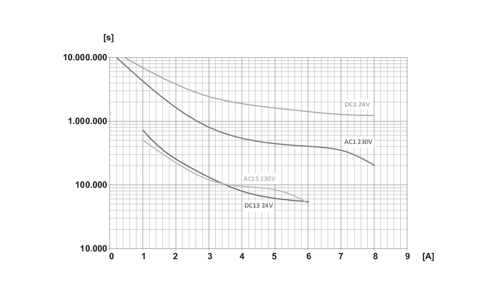
Legend
A Contact load in ampere
s switching cycles
3 Mounting
3.1 General mounting instructions
The safety relay module features degree of protection IP54 for installation in a switch cabinet.
Mounting: snaps onto standard DIN rails to EN 60715.
Hook bottom of enclosure in standard rail and push down until it engages in position.
3.2 Dimensions
Device dimensions (H/W/D): 98 x 22.5 x 115 mm
4 Electrical connection
4.1 General information for electrical connection
- The electrical connection may only be carried out by authorised personnel in a de-energised condition.
- To avoid EMC disturbances, the physical ambient and operational conditions at the place where the product is installed, must meet the provisions laid down in the paragraph "Electromagnetic Compatibility (EMC)" of EN 60204-1.
Settle length x of the conductor: 7 mm
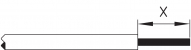 | 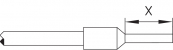 |
- The connection of magnetic safety switches to the SRB-E-... safety relay module is only admitted when the requirements of the standard EN 60947-5-3 are observed.
The following minimum requirements must be met:
• switching capacity: min. 240 mW
• switching voltage: min. 24 VDC
• switching current: min. 10 mA
- For example, the following safety sensors meet the requirements:
• BNS 36-02Z(G), BNS 36-02/01Z(G)
• BNS 260-02Z(G), BNS 260-02/01Z(G)
- Caution! When sensors with LED are wired in the control circuit (protective circuit), the following rated operating voltage must be observed and respected:
• 24 VDC with a max. tolerance of –5 %/+20 %
Otherwise availability problems could occur, especially in series-wired sensors, where a voltage drop in the control circuit is triggered by LEDs for instance.
4.2 Coding of connecting terminals
The plug-in terminal blocks must be arranged according to the coding shown,

4.3 Pin configuration and LED displays
| Clip | Function | LED | Function | |
|---|---|---|---|---|
 | A1 | Operating voltage + 24 VDC / 24 VAC | UB Ui | Operating voltage OK Internal fuse OK |
| A2 | Operating voltage 0 V / 24 VAC | |||
| GND | QS | Cross-wire monitoring active | ||
| X1 | Output start circuit / feedback circuit | |||
| X2 | Input start circuit / feedback circuit | |||
| S11 | Output channel 1 | + 24 VDC | ||
| S21 | Output channel 2 | + 24 VDC without QS 0V with QS | ||
| S12 | Input channel 1 | K1 | Status K1 | |
| S22 | Input channel 2 | K2 | Status K2 | |
| 41/22 | Signalling contact (NC) | |||
| 13/14, 23/24, 33/34 | Safety outputs |
4.4 Wiring examples and configuration
Dual-channel control, shown for a guard door monitor with two position switches where one has a positive break contact; with external reset button j
• Performance level: two-channel actuation, suitable for ↲increasing capacity or number of contacts by means of contactor ↲or relay with positive action contacts
• s = feedback circuit
- Signalling outputs must not be used in safety circuits.

| Key | |
|---|---|
| a) | Safety inputs |
| d) | Outputs |
| e) | Logic |
| f) | Input voltage |
4.5 Start configuration
4.5.1 External reset button
• The external reset button is integrated in the feedback circuit in series.
• The manual start or the activation of the module occurs when the button is pressed (not when it is released!).

4.5.2 Feedback circuit / Automatic start
• The automatic start is programmed by connecting the feedback circuit to the terminals X1-X2. If the feedback circuit is not required, establish a bridge.
- Not admitted without additional measure due to the risk of gaining access by stepping behind.
- Within the meaning of EN 60204-1 paragraph 9.2.3.4.2, the operating mode "automatic start" is only restrictedly admissible. In particular, any inadvertent restart of the machine must be prevented by other suitable measures.

4.6 Sensor configuration
Single channel signal processing

| Rotary switch position | Function |
|---|---|
| 2, 6, 10, 14 | without cross-wire monitoring |
Dual channel signal processing NC / NC
With cross-circuit monitoring
(category 4 – PL e to DIN EN ISO 13849-1 possible)

| Rotary switch position | Function |
|---|---|
| 1, 5, 9, 13 | with cross-wire monitoring |
Without cross-circuit monitoring
(Cat. 4 - PL e to EN ISO 13849-1 only possible with protective wiring)

| Rotary switch position | Function |
|---|---|
| 2, 6, 10, 14 | without cross-wire monitoring |
5 Settings
The safety relay module is delivered ready for operation.
Application 1 is preset in the factory.
- Only touch the components after electrical discharge.
Adjustment of application using rotary “mode” switch
• Open front transparent cover (see fig.).
• Opening is carried out by lifting side with lock.
• Select desired application using rotary mode switch by turning up or down (see 5.3).
• After performing setting, close front cover again.
• Front cover can be secured with a lead seal to protect it from being opened unintentionally

5.1 Adjustable applications
| Rotary switch position | Reset button / feedback circuit | Cross-wire monitoring active | Input- / Sensor configuration |
|---|---|---|---|
| 1, 5, 9, 13 | Yes | Yes | NC / NC |
| 2, 6, 10, 14 | Yes | No | NC / NC |
5.2 Changing setting or application
| Description / procedure | Rotary (mode) switch | System response | LED indications | ||
|---|---|---|---|---|---|
| UB | Ui | QS | |||
| Factory setting | Position 1 | Ready for application 1 | - | - | - |
| Switch operating voltage on | Position 1 | Ready for application 1 | Lights up | Lights up | Lights up |
| Change SRB-E application | |||||
| Switch off operating voltage | Setting application 2 | - | - | - | |
| Switch operating voltage on | Ready for application 2 | Lights up | Lights up | - | |
6 Diagnostic
| LED | Function | Display type |
|---|---|---|
| UB | Ready for operation | Continuously lit |
| No operating voltage at A1 and A2 | Not lit | |
| Ui | Operationally ready and internal fuse OK | Continuously lit |
| No operating voltage at A1 and A2 | Not lit | |
| Internal fuse triggered | ||
| K1 | Relay channel 1 active | Continuously lit |
| Input S12 open, relay K1 deactivated | Not lit | |
| Manual start signal, feedback circuit missing | ||
| Invalid rotary switch setting | ||
| K2 | Relay channel 2 active | Continuously lit |
| Input S22 open, relay K2 deactivated | Not lit | |
| Manual start signal, feedback circuit missing | ||
| Invalid rotary switch setting |
The safety relay module features self-test functions. If a fault is detected, the system adopts a safe mode and leads, if necessary, to undelayed deactivation of all safety outputs.
7 Set-up and maintenance
7.1 Functional testing
The safety function of the safety relay module must be tested. The following conditions must be previously checked and met:
- Correct fixing.
- Check the integrity of the cable entry and connections
- Check the safety relay module's enclosure for damage
- Check the correctness of the set application.
- Check the electrical function of the connected sensor technology and their influence on the safety relay module and the downstream actuators
7.2 Behaviour in the case of faults
In the event of a fault the following procedure is recommended:
1. identify errors using chapter 6.1.
2. Rectify the fault if it is described in the table.
If fault could not be rectified, please contact the manufacturer.
7.3 Setting report
The form for documenting the selected settings of the device can be found in the online document area of the safety relay module. It must be completed accordingly by the customer and attached to the technical documentation of the machine. The setting report must be available whenever a safety check is performed.
7.4 Maintenance
It must be completed accordingly by the customer and attached to the technical documentation of the machine:
1. Check the correct fixing of the safety relay module.
2. Check the cable for damages.
3. Check electrical function.
- If a manual functional check is necessary to detect a possible accumulation of faults, then this must take place during the intervals noted as follows:
• at least every month for PL e with category 3 or category 4 (in accordance with EN ISO 13849-1) or SIL 3 with HFT (hardware fault tolerance) = 1 (in accordance with EN 62061);
• at least every 12 months for PL d with category 3 (in accordance with EN ISO 13849-1) or SIL 2 with HFT (hardware fault tolerance) = 1 (in accordance with EN 62061).
- Damaged or defective components must be replaced.
8 Disassembly and disposal
8.1 Disassembly
The safety relay module must be disassembled in a de-energised condition only.
8.2 Disposal
- The safety relay module must be disposed of in an appropriate manner in accordance with the national prescriptions and legislations.
Schmersal Ibérica, S.L., Rambla P. Catalanes, Nº 12, 08800 Vilanova i la Geltrú
Los datos e información anteriores se han verificado cuidadosamente. Las imágenes pueden diferir del original. Se pueden encontrar más datos técnicos en los manuales de instrucciones. Sujeto a cambios técnicos y errores.
Generado a 15/6/2025 4:03