SFB-EC-8M12-IOP

- 最大8つのセーフティスイッチの接続用
- 内蔵デュアルポートスイッチ
- 保護構造 IP66, IP67
注文データ
| Product type description |
SFB-EC-8M12-IOP |
| 部品番号(注文番号) |
103047531 |
| EAN(欧州部品番号) |
4030661628707 |
| eCl@ss番号、バージョン12.0 |
27-24-26-04 |
| eCl@ss番号、バージョン11.0 |
27-24-26-04 |
| eCl@ss番号、バージョン9.0 |
27-24-26-04 |
| ETIM番号、バージョン7.0 |
EC001599 |
| ETIM番号、バージョン6.0 |
EC001599 |
認証
|
TÜV cULus UKCA |
一般データ
| 規格 |
EN IEC 61131-1 EN IEC 61131-2 EN ISO 13849-1 EN IEC 60947-5-3 EN IEC 61508 |
| ハウジング 材質 |
熱可塑性樹脂性, ポリアミド PA 6 GF |
| 識別ラベルの材質 |
Plastic, Polyamide PA |
| Material of viewing window |
Polyamide PACM 12 |
| Material of electronic encapsulation |
Polyurethane 2K PU |
| 総重量 |
597 g |
一般データ - 仕様
| 一体型システム診断、一般 |
Yes |
安全性評価
| 規格 |
EN ISO 13849-1 EN IEC 61508 |
安全性評価 - 安全人力 2 チャンネル
| Performance Level, up to |
e |
| カテゴリー |
4 |
| Diagnostic Coverage (DC) Level |
99 % |
| PFH値 |
1.10 x 10⁻⁹ /h |
| PFDavg |
9.60 x 10⁻⁵ |
| Safety Integrity Level (SIL), suitable for applications in |
3 |
| 使用期間 |
20 年 |
| Response time of local safety input ⇒ Fieldbus, maximum |
30 ms |
| Notice |
The SFB fulfils the requirements as PDDB (proximity switch with defined behaviour under fault conditions) according to EN 60947-5-3 in combination with magnetic sensors (2 NC contacts) up to PL e / SIL 3. |
安全性評価 - 安全入力 1 チャンネル
| Performance Level, up to |
d |
| カテゴリー |
2 |
| Diagnostic Coverage (DC) Level |
90 % |
| PFH値 |
2.30 x 10⁻⁷ /h |
| PFDavg |
2.00 x 10⁻² |
| Safety Integrity Level (SIL), suitable for applications in |
1 |
| 使用期間 |
20 年 |
| Response time of local safety input > Fieldbus, maximum |
30 ms |
| Test interval for error detection |
10 s |
安全性評価 - 安全出力 1 チャンネル
| Performance Level, up to |
d |
| カテゴリー |
3 |
| Diagnostic Coverage (DC) Level |
90 % |
| PFH値 |
1.00 x 10⁻⁷ /h |
| PFDavg |
8.80 x 10⁻³ |
| Safety Integrity Level (SIL), suitable for applications in |
2 |
| 使用期間 |
20 年 |
| Reaction time Fieldbus > local safety output |
50 ms |
安全性評価 - 安全出力 2 チャンネル
| Performance Level, up to |
e |
| カテゴリー |
4 |
| Diagnostic Coverage (DC) Level |
99 % |
| PFH値 |
1.20 x 10⁻⁹ /h |
| PFDavg |
1.10 x 10⁻⁴ |
| Safety Integrity Level (SIL), suitable for applications in |
3 |
| 使用期間 |
20 年 |
| Reaction time Fieldbus > local safety output |
50 ms |
機械的データ
| 取り付け |
ネジ |
| Type of the fixing screws |
2x M6 |
| Tightening torque of the fixing screws, maximum |
3 Nm |
| 固定ネジの種類、ビューイングウィンドウ |
2x TX10 (Torx) |
| 表示ウィンドウ取り付けネジの締め付けトルク、最大 |
0.6 Nm |
機械的データ - 電気機械式
| 端子 コネクター |
M12 コネクターソケット/コネクター |
| 端子コネクター, 入力/出力 |
X0 - X7: M12, 8-pole, A-coded |
| Terminal Connector, Power I/O |
M12 POWER, 4-pole, T-coded |
| Terminal Connector, Field bus |
M12, 4-pole, D-coded |
| 電気接続部の締付けトルク、 最小 |
0.8 Nm |
| Tightening torque of electrical connection, maximum |
1.5 Nm |
機械的データ - 寸法
| 長さ |
222.8 mm |
| 幅 |
63 mm |
| 高さ |
36.1 mm |
環境条件
| 保護等級 |
IP66 IP67 |
| 使用周囲温度 |
-25 ... +55 °C |
| 保管および輸送温度 |
-25 ... +70 °C |
| 相対湿度, 最小 |
10 % |
| 相対湿度, 最大 |
95 % |
| Note (Relative humidity) |
non-condensing |
| 耐振動 |
10 ~ 150 Hz, 振幅 0.35 mm / 5 g |
| 耐衝撃 |
30 g / 11 ms |
| Protection class |
III |
| Permissible installation altitude above sea level, maximum |
2,000 m |
環境条件 - 絶縁値
| 定格絶縁電圧 |
32 VDC |
| 定格インパルス耐電圧 |
0.8 kV |
| Overvoltage category |
III |
| 汚染度 |
3 |
電気的データ
| 動作電圧 |
24 VDC -15 % / +10 % (PELV電源により安定化) |
| 動作電流 |
200 mA |
| 定格動作電圧 |
24 VDC |
| 動作電流 |
10,000 mA |
| 注意(電気的データ、ヒューズ定格) |
External fuse protection required ≤ 10A slow blow when used to UL 61010. |
| 準備時間、最大 |
12,000 ms |
| Device Watchdog Time |
12 ms |
| Device Acknowledgement Time, maximum |
25 ms |
| Reaction Time Safety Input, maximum |
30 ms |
| Reaction Time Safety Output, maximum |
50 ms |
電気的データ - 通信プロトコル
| Feldbus Protokoll |
EtherCAT / FSoE |
| Fieldbus specification |
V1.0.10 |
| Specification safety fieldbus |
V1.2.0 |
| Transfer rate |
100 Mbit/s Full Duplex |
| Adressing |
Topology dependent |
| Integrated switch |
Dual Port, 100 Mbit/s |
| Service interface |
WEB-Interface HTTP |
電気データ-デバイスポート
| Bezeichnung, Geräteanschlüsse |
X0 ... X7 |
| ケーブルの長さ、デバイスポート |
30 m |
電気的データ - 外部機器への電源供給
| Designation, Power supply |
A1とA2 |
| 定格動作電圧 |
24 VDC |
| 定格使用電流 |
800 mA |
| 内部ヒューズ |
1.5 A (統合された自動リセット可能なヒューズ) |
Electrical data - Safety digital inputs
| Designation, Safety inputs |
X1 and X2 |
| フェイルセーフ入力のスイッチングの閾値 |
−3 V … 5 V (Low) 13 V ... 30 V (High) |
| 24Vの時の安全入力の消費電流 |
6 mA |
| 許容残留駆動電流 |
1 mA |
| テストパルス幅、最低限 |
0.01 ms |
| テストパルス幅、最大 |
1 ms |
| テストパルス間隔、最小 |
20 ms |
| テストパルス間隔、最大 |
120,000 ms |
| Classification ZVEI CB24I, Sink |
C1 |
| Classification ZVEI CB24I, Source |
C1 C2 C3 |
Electrical data - Safety digital outputs
| Designation, Safety outputs |
DO |
| 安全出力 |
short-circuit proof, p-type |
| Voltage drop Ud, maximum |
2 V |
| Leakage current Ir, maximum |
0.5 mA |
| Voltage, Utilisation category DC-12 |
24 VDC |
| Current, Utilisation category DC-12 |
0.8 A |
| Voltage, Utilisation category DC-13 |
24 VDC |
| Current, Utilisation category DC-13 |
0.8 A |
| Note, Utilisation category DC-13 |
誘導負荷 |
| 開閉頻度、最大 |
1 Hz |
| テストパルス幅、最大 |
1 ms |
| テストパルス間隔、最小 |
15 ms |
| テストパルス間隔、最大 |
500 ms |
| Classification ZVEI CB24I, Source |
C1 |
| Classification ZVEI CB24I, Sink |
C1 |
電気的データ - 診断入力 / FB-インターフェース
| 指定、診断入力/FBインターフェース |
DI |
| スイッチングの閾値 |
−3 V … 5 V (Low) 15 V … 30 V (High) |
| 24Vの時の消費電流 |
12 mA |
| 入力デバウンスフィルター |
10 ms |
| データ転送速度 Bインターフェース |
19,2 kBaud |
電気的データ - テストパルス出力
| Designation, Test pulse outputs |
Y1およびY2 |
| コントロールエレメントのデザイン |
短絡保護あり, PNP型 |
| Voltage drop Ud, maximum |
1 V |
| 漏電 lr, 最大 |
0.5 mA |
| Voltage, Utilisation category DC-12 |
24 VDC |
| Y1・定格・電流・24・V時 |
15 mA |
| Y2・定格・電流・24・V時 |
10 mA |
| Y2・定格・電流・0・V時 |
30 mA |
| テストパルス間隔、標準 |
500 ms |
| テストパルス幅、最大 |
1 ms |
| Classification ZVEI CB24I, Sink |
C1 |
| Classification ZVEI CB24I, Source |
C1 |
LED状態表示 - LED 01
| LED status |
Error LED device port |
| LED position |
E: 0 ... 7 |
| LED colour |
green/red |
LED状態表示 - LED 02
| LED status |
Input LED device port |
| LED position |
I: 0 ... 7 |
| LED colour |
Yellow |
LED状態表示 - LED 03
| LED status |
イーサネットポート |
| LED position |
L / A: IN + OUT |
| LED colour |
Green |
LED状態表示 - LED 05
| LED status |
EtherCAT ラン LED |
| LED position |
"RUN": モジュール |
| LED colour |
Green |
LED状態表示 - LED 06
| LED status |
EtherCAT エラー LED |
| LED position |
"Err": モジュール |
| LED colour |
Red |
LED状態表示 - LED 07
| LED status |
フィールドボックス Diag-LED |
| LED position |
"Diag": モジュール |
| LED colour |
green/red |
LED状態表示 - LED 08
| LED status |
Power-LED fieldbox |
| LED position |
"Pwr": Module |
| LED colour |
Green |
その他のデータ
| 注意 (アプリケーション) |
Safe field box with decentralised I/Os |
言語フィルター
データシート
Operating instructions and Declaration of conformity
System Manual
BG-test certificate
UL Certificate
UKCA certificate
Device description files
General information
Brochure
SISTEMA-VDMA library
Adobe Readerの最新版をダウンロードしてください
Product picture (catalogue individual photo)

103035090 ACC-PFB-SFB-LAB-SN-20PCS-V2
- Designation label V2
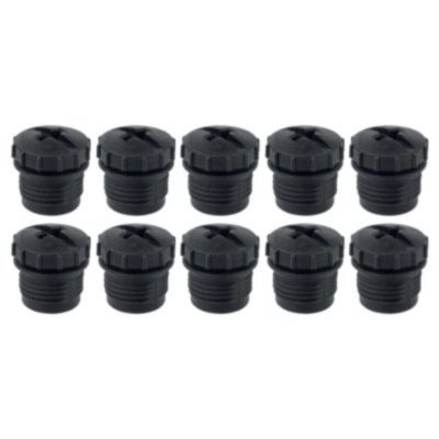
103013920 ACC-PFB-SFB-M12-PCAP-10PCS
- M12 Protecting caps
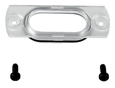
103041447 ACC-PFB-SFB-VWIN-SCR
- ネジ付き覗き窓

103041446 ACC-SFB-EARTH-STRAP-100MM
- アースストラップ完成
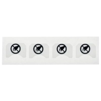
103013919 ACC-PFB-SFB-SLLAB-4PCS
- Seal label viewing window
シュメアザー株式会社, 〒222-0033 横浜市港北区新横浜3-9-5, 新横浜第3東昇ビル
データと詳細は完全にチェックされました。画像は元の画像と異なる場合があります。技術的なデータはマニュアルで見られます。技術的に変更されたり、エラーの可能性があります。
Generated on 2025/07/01 0:14
最近見た製品
TV8S 355-02Z-M20
SMS 4-800-1300
PS216-Z11-K250
G50-025M22/11Y-1601-3

PS226-T11-K210
Z4VH 335-11Z-RMS-U180
PS226-Z11-K210