Bezpieczne wyłączanie i monitorowanie
Wyłączniki bezp. z oddzielnym aktywatorem
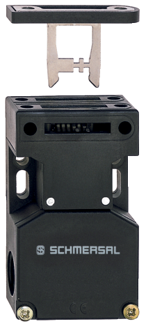
Obszar stosowania:
Wyłączniki bezpieczeństwa z oddzielnym aktywatorem nadają się do przesuwnych, uchylnych i zdejmowanych osłon, które muszą być zamknięte, aby zagwarantować wymaganą niezawodność eksploatacji. Można je montować na gotowych profilach i na istniejącym wyposażeniu.
W połączeniu z modułami monitorującymi bezpieczeństwa wszystkie wyłączniki pozycyjne klasy 2 pokazane w tym rozdziale uzyskują kategorię sterowania 3 do 4 wg ISO 13849-1.
Budowa i zasada działania:
W przypadku wyłączników bezpieczeństwa klasy 2 blok kontaktów nie jest fizycznie połączony z aktywatorem, ale funkcjonalnie uruchamiany przy zamykaniu i otwieraniu osłony. Podczas otwierania urządzenia ochronnego aktywator zostaje odłączony od urządzenia podstawowego. W trakcie tego procesu następuje zmiana stanu zestyków na przeciwny.
Stopień ochrony dla wszystkich wyłączników bezpieczeństwa: IP 67. Wyłączniki bezpieczeństwa mogą być mocowane w dowolnej pozycji montażowej.
Blokady elektromagnetyczne
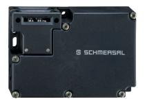
Obszar stosowania:
Elektromagnetyczne blokady bezpieczeństwa typoszeregu AZM, działające w połączeniu z elementami sterującymi maszyny, np. modułami kontroli ruchu lub modułami z układem zegarowym, zapewniają, że otwarcie osłon bezpieczeństwa nie będzie możliwe do momentu zaniku warunków niebezpiecznych (np. ruchów dobiegowych).
Elektromagnetyczne blokady bezpieczeństwa używane są także w przypadkach, w których otwarcie osłony bezpieczeństwa stanowi niedopuszczalną ingerencję osób nieupoważnionych w proces produkcji.
Budowa i zasada działania:
W elektromagnetycznych blokadach bezpieczeństwa typoszeregu AZM blok kontaktów nie jest fizycznie połączony z aktywatorem, ale funkcjonalnie uruchamiany przy zamykaniu i otwieraniu osłony. Gdy osłona bezpieczeństwa jest otwierana w stanie niezaryglowanyk, aktywator jest oddzielany od blokady bezpieczeństwa. W trakcie tego procesu następuje zmiana stanu zestyków na przeciwny.
Ryglowanie jest realizowane za pomocą trzpienia w taki sposób, że aktywatora nie można wyciągnąć z blokady. Obwód sterujący maszyny może być uruchomiony jedynie po wprowadzeniu aktywatora do blokady i ustawieniu trzpienia ryglującego w pozycji zablokowania, kontrolowanej przez odpowiedni zestyk.
Dostępne są dwa tryby ryglowania W przypadku trybu „ryglowania sprężyną” trzpień ryglujący jest przytrzymywany w blokadzie przez sprężynę. Po podaniu napięcia na cewkę elektromagnesu następuje odryglowanie i otwarcie zestyków NC. W tym momencie można otworzyć osłonę bezpieczeństwa. W przypadku „ryglowania napięciem"1) sposób działania ulega odwróceniu.
Blokady elektromagnetyczne AZM 150, 161, 170, 190 i 415 wyposażone są w zabezpieczenia przeciwko nieprawidłowemu zaryglowaniu W zależności od typu urządzenia możliwe jest również indywidualne kodowanie aktywatora.
Elektromagnetyczne blokady bezpieczeństwa mogą być montowane w dowolnej wymaganej pozycji montażowej. Elektromagnetyczne blokady bezpieczeństwa wykonywane są w stopniu ochrony IP 54, IP 65 lub IP 67.
1) Blokady te mogą być używane jedynie po dokładnej analizie ryzyka wypadków, ponieważ osłona bezpieczeństwa może w tym wypadku być natychmiast otwarta w razie awarii zasilania elektrycznego!
Wyłączniki pozycyjne
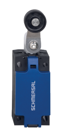
Obszar stosowania:
Wyłączniki pozycyjne z funkcją bezpieczeństwa nadają się do przesuwnych i uchylnych osłon, które muszą być zamknięte, aby zagwarantować wymagane bezpieczeństwo eksploatacji.
W połączeniu z modułami monitorującymi bezpieczeństwa wszystkie wyłączniki pozycyjne klasy 1 pokazane w tym rozdziale uzyskują kategorię sterowania 3 do 4 wg ISO 13849-1.
Dalsze zastosowania wyłączników pozycyjnych klasy 1 to cały szereg rozmaitych zastosowań w pozycjonowaniu. Zróżnicowane wymagania, które spotyka się praktyce, zaspokajane są za pomocą zróżnicowanego asortymentu elementów aktywujących.
Budowa i zasada działania:
W wyłącznikach pozycyjnych klasy 1 w sposób wymuszony łączone jest urządzenie bezpieczeństwa i zestyk NC z wymuszonym rozwarciem.
Stopień ochrony dla wszystkich wyłączników bezpieczeństwa: IP 67. Wyłączniki bezpieczeństwa mogą być mocowane w dowolnej pozycji montażowej.
Wyłączniki bezpieczeństwa dla osłon uchylnych
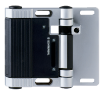
Obszar stosowania:
Omawiane wyłączniki bezpieczeństwa przeznaczone są do uchylnych osłon zabezpieczających, które muszą być zamknięte dla zapewnienia odpowiedniego bezpieczeństwa pracy.
Dzięki szerokiemu asortymentowi wyłączników bezpieczeństwa przeznaczonych do osłon uchylnych możliwe jest spełnienie szerokiego spektrum wymagań napotykanych w praktyce.
W zależności od konkretnej wersji wyłącznika możliwa jest ochrona zarówno małych drzwiczek i klap serwisowych, jak i ciężkich drzwi uchylnych w maszynach i urządzeniach w sposób zapewniający łatwe ustawienie i konserwację.
Budowa i zasada działania:
Generalna zaleta pokazanych tu wyłączników bezpieczeństwa to zintegrowana krzywka z wyłącznikiem bezpieczeństwa. Dzięki temu możliwe było spełnienie wymagań normy EN 1088, takich jak odpowiednie połączenie krzywki i dźwigni, jak również ochrona przed manipulacjami przez osoby nieupoważnione.
Taka budowa wyłącznika pozwala użytkownikowi na obniżenie kosztów poprzez uniknięcie konieczności montażu specjalnie zaprojektowanej krzywki.
Omawiane wyłączniki bezpieczeństwa posiadają zestyki wolnoprzełączające.
Czujniki bezpieczeństwa
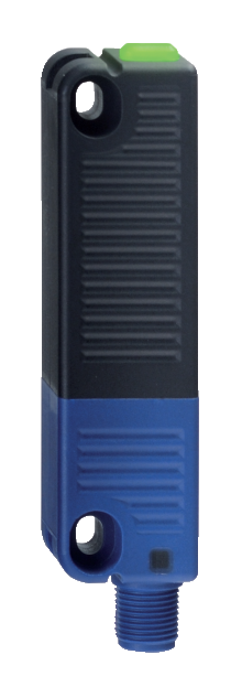
Obszar stosowania:
Magnetyczne czujniki bezpieczeństwa służą do monitorowania pozycji przesuwnych, uchylnych i zdejmowanych osłon ochronnych. Czujniki bez zintegrowanego modułu analizującego mogą być stosowane tylko w zabezpieczeniach wg IEC 60947-5-3 w połączeniu z modułem bezpieczeństwa dla zapewnienia ochrony do kategorii sterowania 4 wg ISO 13849-1.
Zastosowanie magnetycznych czujników bezpieczeństwa jest szczególnie korzystne w przypadkach, w których możliwe jest występowanie wyjątkowego poziomu zabrudzenia lub w których konieczne jest spełnienie wysokich norm higienicznych dzięki prostemu czyszczeniu urządzeń.
Inną zaletą jest możliwość montażu ukrytego pod materiałami niemagnetycznymi. Dzięki temu możliwa jest aranżacja powierzchni roboczych i przestrzeni magazynowych bez gromadzących brud krawędzi lub innych wymaganych z powodów funkcjonalnych wycięć lub otworów.
Magnetyczne czujniki bezpieczeństwa typoszeregu BNS mogą być także wykorzystywane w przypadkach, w których nie jest możliwe precyzyjne zamykanie osłon i wymagane są większe tolerancje.
Budowa i zasada działania:
Urządzenia te składają się z wielokanałowych magnetycznych czujników bezpieczeństwa oraz magnesu.
Wszystkie magnetyczne czujniki bezpieczeństwa są zamknięte w obudowach z tworzywa termoplastycznego lub stali nierdzewnej i spełniają wymagania stopnia ochrony IP 67 lub 65.
Linkowe wyłączniki stopu awaryjnego
Obszar stosowania:
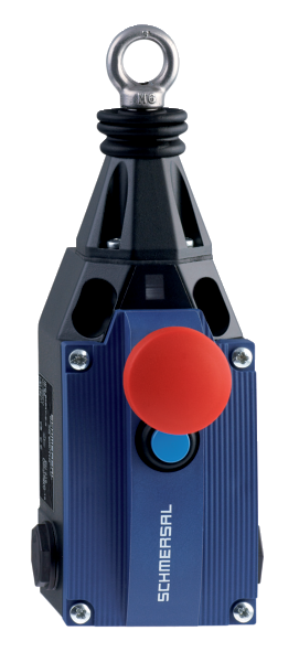
Wyłączniki linkowe stopu awaryjnego są montowane w maszynach i sekcjach instalacji, które nie mogą być zabezpieczone osłonami. W odróżnieniu od grzybkowych przycisków E-Stop w przypadku wyłącznika linkowego polecenie zatrzymania awaryjnego może być zainicjowane z dowolnego punktu linki.
W połączeniu z jednym z modułów bezpieczeństwa typoszeregu AES i AZR wyłączniki linkowe stopu awaryjnego mogą być używane dla kategorii sterowania 3 lub 4 wg ISO 13849-1.
Budowa i zasada działania:
Wszystkie wyłączniki linkowe stopu awaryjnego spełniają wymagania normy europejskiej EN ISO 13850. Są one oparte na wymuszonym połączeniu pomiędzy zestykami NC i linką. Wyłączniki linkowe stopu awaryjnego są uruchamiane przez naciągnięcie wstępne linki, tj. wówczas, gdy zestyki NC zostaną zamknięte, zaś zestyki NO otwarte.
Wszystkie wyłączniki linkowe stopu awaryjnego są wyposażone w kontrolę zerwania linki. W przypadku pociągnięcia lub zerwania linki, zestyki NC zostają w sposób wymuszony rozwarte, zaś zestyki NO zamknięte. Następnie można ponownie ustawić wyłącznik linkowy zatrzymania awaryjnego w stan pracy przez odryglowanie.
Przycisk stopu awaryjnego
Obszar stosowania:
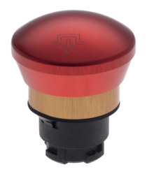
Urządzenia sterujące są bardzo ważnym elementem interfejsu człowiek-maszyna w obszarze zastosowań przemysłowych. Są stosowane np. szafach i tablicach sterowniczych, panelach sterowania oburęcznego, w windach oraz w urządzeniach transportowych i przenośnikach. Ręczna aktywacja tych urządzeń rozpoczyna sekwencje robocze i procedury funkcjonalne lub służy do ich zakończenia.
Budowa i zasada działania:
Urządzenia sterownicze są dostępne w formie przycisków, manipulatorów (joysticków) i przełączników. Główki są połączone bagnetem z blokami zestyków.
Panele sterownicze

Wyrób wysokiej jakości zamiast "samoróbek"
Podstawą typoszeregu BDF jest smukła, wykonana z odpornego tworzywa obudowa, którą można szybko i bez trudu montować na popularnych systemach profili aluminiowych wykorzystywanych w konstrukcji maszyn. Obudowa mieści do czterech elementów sterowniczych, które użytkownik może wybrać spośród szerokiej gamy podświetlanych przycisków, przełączników, lampek sygnalizacyjnych LED, stacyjek i zgodnych z normami wyłączników stopu awaryjnego.
Dostosowane do potrzeb użytkownika
Wszystkie elementy sterownicze mają takie same zestyki. Dzięki temu, użytkownik może wybrać ich pozycję na panelu zależnie od potrzeb. Także w kwestii wkładek opisowych panele BDF można dostosować do indywidualnych wymagań. W tym celu dostępne są uchwyty na etykiety wraz z plastikowymi pokrywkami. W uchwytach tych można umieszczać dwuwarstwowe etykiety identyfikacyjne. W fazie badań inżynierowie firmy Schmersal przeprowadzili rozmowy z wieloma klientami na temat pożądanych cech, jakie powinny posiadać takie panele. Wnioski z tych rozmów wykorzystano przy projektowaniu typoszeregu BDF.
Bariery świetlne bezpieczeństwa
Zakres zastosowania:
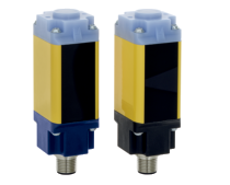
Optoelektroniczne urządzenia bezpieczeństwa są wykorzystywane do ochrony wejść oraz niebezpiecznych punktów i obszarów.
Bariery świetlne bezpieczeństwa typoszeregu SLB 240 i SLB 440 są wykorzystywane do ochrony wejść do niebezpiecznych obszarów. Występująca w wersji typu 2 (PL c) i typu 4 (PL e) rodzina produktów może być bezpośrednio zintegrowana w obwodzie bezpieczeństwa.
Budowa i zasada działania:
Wersje SLB oferują 4 wersje kodowania, dzięki czemu można eksploatować do 4 par czujników w jednym kierunku w jednej aplikacji bez wzajemnych zakłóceń. Dostępne są następujące tryby pracy: ustawianie, tryb automatyczny, tryb ponownego uruchomienia i tryb diagnostyczny.
Wersja SLB440-H może być stosowana na zewnątrz dzięki wbudowanemu ogrzewaniu dla ujemnych temperatur i oferuje zasięg aż do 75 m.
Kurtyny i bariery świetlne bezpieczeństwa
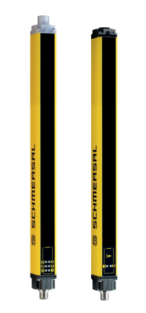
Obszar stosowania:
Optoelektroniczne urządzenia bezpieczeństwa są wykorzystywane od ochrony wejść oraz niebezpiecznych punktów i obszarów.
Wielopromieniowe bariery świetlne bezpieczeństwa i kurtyny świetlne bezpieczeństwa typoszeregu SLG/SLC mogą być zintegrowane w ramach ochrony maszyny lub instalacji nawet przy bardzo ograniczonej przestrzeni dzięki swojej bardzo zwartej budowie.
Urządzenia te są często wykorzystywane przy prasach do zabezpieczenia niebezpiecznych punktów lub stref. W zależności od rozdzielczości danej wielopromieniowej bariery świetlnej bezpieczeństwa lub kurtyny świetlnej bezpieczeństwa możliwa jest ochrona osób, rąk lub nawet palców. Wielopromieniowe bariery świetlne bezpieczeństwa i kurtyny świetlne bezpieczeństwa typoszeregu SLG/SLC osiągają kategorię sterowania 4 wg ISO 13849-1.
Budowa i zasada działania:
W optoelektronicznych urządzeniach bezpieczeństwa typoszeregów SLB/SLC/SLG nadajnik i odbiornik umieszczone są w oddzielnych obudowach. Z nadajnika jest wysyłany niewidzialny sygnał w podczerwieni, który jest następnie odbierany przez system soczewek odbiornika i analizowany przez zintegrowany lub zewnętrzny moduł bezpieczeństwa. W przypadku przerwania wiązki świetlnej następuje przełączenie bezpiecznych wyjść.
Wszystkie wymienione tu optoelektroniczne urządzenia bezpieczeństwa nie wymagają konserwacji i są proste w montażu i konfiguracji.
Panele sterowania oburęcznego
Obszar stosowania:
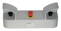
Panele sterowania oburęcznego należą do urządzeń ochronnych. Służą do wymuszenia bezpiecznego położenia obu rąk operatora maszyny, co generuje sygnał sterujący dla ruchu mogącego stanowić zagrożenie. Panele sterowania oburęcznego zapewniają więc uniknięcie udziału operatora w procesach, którym towarzyszy niebezpieczny ruch, po uruchomieniu maszyny.
Obszary zastosowania obejmują prasy w przemyśle metalowym, metalurgii proszków, przemysł drukarski i papierniczy, urządzenia do cięcia i podobne, jak również maszyny w przemyśle gumowym, tworzyw sztucznych i chemicznym.
Panele sterowania oburęcznego stanowią preferowane urządzenia bezpieczeństwa do stosowania przy ustawianiu materiałów i operacjach z jednym uderzeniem roboczym w ramach procesów podawania i odbierania materiałów.
Więcej informacji dotyczących stosowania paneli sterowania oburęcznego i ich analizę zamieszczono w normie EN 574.
Dla uzyskania kategorii 0 wg EN 60204-1, wymagany jest dodatkowy obwód analizujący. Moduły bezpieczeństwa dla bezpiecznej analizy sygnałów z paneli sterowania oburęcznego oraz urządzeniach stopu awaryjnego omówione są w rozdziale xx.
Budowa i zasada działania:
Panele sterowania oburęcznego są urządzeniami bezpieczeństwa, które do aktywacji wymagają jednoczesnego użycia obu rąk. Dzięki wymuszonemu umiejscowieniu obie ręce znajdują się z dala od niebezpiecznego obszaru. Dla uruchomienia maszyny lub instalacji, które mogą być niebezpieczne, umiejscowienie rąk jest kontrolowane przez cały czas występowania zagrożenia.
Panele sterowania oburęcznego są montowane standardowo z przyciskiem stopu awaryjnego wg EN ISO 13850 i dwoma urządzeniami sterującymi. Ponadto, nad elementami roboczymi montowane są osłony ochronne, które zapobiegają prostym manipulacjom przy elementach bezpieczeństwa przy pomocy na przykład rąk, łokci, brzucha, bioder, ud lub kolan.
Norma EN 574 rozróżnia różne typy obwodów paneli sterowania oburęcznego, odpowiednio do ich technicznego stopnia bezpieczeństwa sterowania. W tym kontekście wybór typu zależy od analizy i oceny ryzyka.
Urządzenie zezwalające

Obszar stosowania:
Wyłączniki zezwalające są stosowane – w razie potrzeby wraz z innymi środkami bezpieczeństwa – do ochrony osób przed potencjalnie niebezpiecznymi sytuacjami, gdy konieczne jest całkowite lub częściowe wyłączenie systemu bezpieczeństwa maszyny w specjalnych trybach roboczych.
Te specjalne sytuacje obejmują zazwyczaj konfigurowanie maszyny, prace serwisowe lub obserwację procesu. W przypadku zwolnienia przycisku przez operatora lub - w przypadku wersji 3-stopniowej - wciśnięcia przycisku do oporu poprzez pozycję środkową, maszyna zostaje bezpiecznie zatrzymana.
Naciskowe urządzenia bezpieczeństwa
Obszar stosowania:
Naciskowe urządzenia bezpieczeństwa, aktywowane przez kontakt fizyczny, służą do zatrzymywania niebezpiecznego ruchu maszyn. Zróżnicowanie zastosowań wymaga konstrukcyjnie odmiennych urządzeń.
Listwy naciskowe bezpieczeństwa
Listwy naciskowe bezpieczeństwa typoszeregu SE są przeznaczone do zabezpieczania miejsc, w których grozi zgniecenie lub ścięcie, takich jak osłony, stoły i platformy podnośne, półki w systemach składowania ruchomego, stoły robocze, dźwigi magazynowe, drzwi dźwigów, rampy załadunkowe, urządzenia podnoszące i obracające lub bramy przemysłowe. Zatrzymują one natychmiast niebezpieczny ruch, zapobiegając w ten sposób obrażeniom u osób lub szkodom materialnym.
Klapy bezpieczeństwa
Klapy bezpieczeństwa typoszeregu SL 300 zostały zaprojektowane do ochrony ludzi i maszyn w maszynach wyposażonych w duże otwory do wprowadzania lub podawania materiału.
Maty bezpieczeństwa
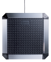
Maty naciskowe bezpieczeństwa typoszeregu SMS są wykorzystywane do zabezpieczenia powierzchni w strefach niebezpiecznych przy maszynach i instalacjach, w których występują niebezpieczne ruchy. W zależności od kształtu obszaru, który ma być chroniony można ułożyć i połączyć elektrycznie kilka mat. W przypadku pobudzenia maty naciskowej bezpieczeństwa następuje zatrzymanie maszyny.
W połączeniu z odpowiednim modułem bezpieczeństwa opisane powyżej systemy osiągają kategorię sterowania 3, 1 lub 4 wg ISO 13849-1.
Budowa i zasada działania:
Listwy naciskowe bezpieczeństwa typoszeregu SE składają się z 3 elementów podstawowych, tj. profilu aluminiowego, profilu gumowego i zestawu nadajnik-odbiornik.
Analizowane jest odkształcenie profilu gumowego listwy bezpieczeństwa. Centralnym elementem systemu jest bezpieczny w razie uszkodzenia zespół nadajnika i odbiornika na obu końcach profilu gumowego. Odkształcenie gumowego profilu osłabia lub przerywa sygnał podczerwony przesyłany pomiędzy nadajnikiem i odbiornikiem. Podłączony moduł bezpieczeństwa analizuje osłabienie sygnału podczerwonego i zatrzymuje niebezpieczny ruch. Powyższa procedura pomiaru spełnia wymagania bezpieczeństwa kategorii sterowania 4 wg ISO 13849-1. Dostępne są także rozwiązania dla zastosowań w kategorii 1.
Norma EN ISO 13856-2 określa wymagania dla listew naciskowych bezpieczeństwa i opisuje ich budowę i homologowanie. W normie tej zdefiniowane są także cechy związane z bezpieczeństwem, takie jak zakres temperatury roboczej, czasy reakcji, siły czynne, przesunięcia wyzwalające działanie i dodatkowe zakresy ruchu.
Norma ISO 13849-1 opisuje wytyczne dla projektowania elementów sterowania maszyn związanych z bezpieczeństwem.
Konieczne jest określenie ryzyka związanego z użytkowaniem pojedynczej maszyny lub zespołu. Im wyższe jest to ryzyko, tym ostrzejsze są wymagania bezpieczeństwa dotyczące sterowania.
Listwy naciskowe bezpieczeństwa typoszeregu SE z podłączonym modułem bezpieczeństwa typoszeregu SE-400C spełniają wymagania bezpieczeństwa kategorii sterowania 4. Nawet w przypadku dwóch błędów w systemie listwa naciskowa bezpieczeństwa zapewni bezpieczne i skuteczne zatrzymanie pojedynczej maszyny lub zespołu.
Dla zastosowań w kategorii sterowania 1 wg ISO 13849-1 stosujemy listwy naciskowe bezpieczeństwa typoszeregu SE z modułem bezpieczeństwa SE-100C.
W przypadku stosowania listew naciskowych bezpieczeństwa należy upewnić się, że prędkość niebezpiecznego ruchu jest mniejsza niż maksymalna prędkość zadziałania listwy naciskowej bezpieczeństwa. Konieczne jest dostosowanie do siebie dystansu zatrzymania niebezpiecznych elementów oraz wysokości profilu. Dystans zatrzymania musi być na tyle krótki, aby siła oddziałująca na zagrożone części ciała nie przekroczyła dopuszczalnej wartości granicznej. Jeżeli dodatkowy zakres ruchu wybranej listwy bezpieczeństwa jest niewystarczający, należy albo zmniejszyć dystans zatrzymania maszyny, albo zastosować inny model o zwiększonej wysokości profilu gumowego.
Wymagany minimalny dodatkowy zakres ruchu należy obliczać przy współczynniku bezpieczeństwa wynoszącym przynajmniej 1,2. Współczynnik bezpieczeństwa należy zwiększyć, jeżeli na dodatkowy zakres ruchu wpływ mają inne elementy maszyny. (patrz EN 13856-2 Załącznik C)
Klapy bezpieczeństwa SL 300 składają się z klapy, profilu nośnego i wyłącznika pozycyjnego klasy 1. Aktywacja profilu klapy powoduje rozłączenie wyłącznika pozycyjnego, a przez to wyłączenie odpowiedniej maszyny.
Maty bezpieczeństwa SMS 4/5 składają się z dwóch oddzielnych płyt stalowych przewodzących prąd elektryczny. Płyty są oddzielone od siebie przy pomocy taśm izolujących. Konstrukcja jest zalana w odpornym mechanicznie tworzywie Plastisol, wysoce odpornym na chemikalia.
Przy aktywacji maty bezpieczeństwa, wewnętrzne stalowe płyty lekko się uginają, powodując zwarcie obwodu elektrycznego. Sygnał ten jest analizowany przez podłączony moduł bezpieczeństwa, który powoduje zatrzymywanie maszyny.
Wyłączniki nożne
Obszar stosowania:
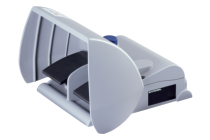
Wyłączniki nożne są montowane jako przełączniki uruchamiające w maszynach i instalacjach w przypadku, gdy nie jest możliwe sterowanie przy pomocy rąk.
Budowa i zasada działania:
Wyłączniki nożne bezpieczeństwa mają osłonę ochronną, która zabezpiecza je przed niezamierzoną aktywacją. Przy naciśnięciu pedału do określonego punktu zestyk NO jest zamykany. Jeżeli w przypadku niebezpieczeństwa pedał zostanie wciśnięty poza wspomniany punkt, wówczas zestyk NC z wymuszonym rozwarciem zostaje otwarty i mechanicznie zablokowany. Operację resetowania wykonuje się za pomocą przycisku. Podczas tej operacji wyłącznik nie przechodzi przez punkt włączania.
Wyłączniki nożne wykonywane są w stopniu ochrony IP 65.
AS interface safety at work

Obszar stosowania:
Łatwo, bezpiecznie i niezawodnie
AS-Interface Safety at Work (SaW) jest pierwszym systemem magistrali bezpieczeństwa opartym na otwartym standardzie AS-International. Elementy bezpieczeństwa, takie jak urządzenia sterujące stopu awaryjnego, wyłączniki bezpieczeństwa, blokady elektromagnetyczne lub świetlne kurtyny bezpieczeństwa są w prosty sposób podłączane do żółtego kabla AS-Interface. Dla analizy sygnałów bezpieczeństwa w systemie AS-Interface stosuje się moduł bezpieczeństwa.
Budowa i zasada działania:
Standard AS-Interface zgodny z EN 50295
Po integracji AS-Interface SaW sieć AS-Interface będzie nadal działać w niezmieniony sposób. Podstawę instalacji AS-Interface w dalszym ciągu stanowić będą dobrze znane elementy, takie jak urządzenie nadrzędne AS-Interface, standardowy zasilacz czy żółty kabel AS-Interface. Dzięki temu istniejąca maszyna może być łatwo wyposażona w dodatkowe elementy AS-i SaW.
Serce bezpieczeństwa
Moduł monitorujący bezpieczeństwo kontroluje informacje wszystkich komponentów bezpieczeństwa przekazywane przez sieć AS-Interface i przełącza urządzenie w bezpieczny stan w przypadku zadziałania obwodu bezpieczeństwa lub błędu jednego z komponentów. Moduł bezpieczeństwa jest wyposażony w jedną lub dwie pary redundantnych wyjść bezpiecznych, co umożliwia uzyskanie kategorii sterowania 4 wg ISO 13849-1. Każda funkcja bezpieczeństwa modułu może być skonfigurowana przy pomocy łatwego w obsłudze oprogramowania, działającego na zasadzie przeciągania i upuszczania elementów. Następnie konfiguracja jest zgrywana do modułu bezpieczeństwa i zabezpieczana hasłem.
Bezpieczny mechanizm transmisji
Protokół komunikacyjny dla zastosowań związanych z bezpieczeństwem jest oparty na niezmienionej transmisji standardu AS-Interface. Każdorazowo, przy zapytaniu urządzenia nadrzędnego AS-Interface każde urządzenie bezpieczeństwa odpowiada skonfigurowanym wcześniej komunikatem. Przesłana informacja jest analizowana i w przypadku odchylenia od skonfigurowanych wcześniej wartości otwierane są wyjścia bezpieczne. Maksymalny czas odpowiedzi dla bezpiecznego wyłączenia wynosi 40 ms.
Zmniejszenie kosztów dzięki AS-Interface Safety at Work
Zmniejszanie kosztów i czasu instalacji – to niekończąca się historia. Podczas instalacji i rozruchu maszyny, jak również podczas prac konserwacyjnych, AS-Interface SaW wspiera użytkownika zintegrowaną diagnostyką systemową. Zapewnia ona szczegółowe informacje o przyczynie i miejscu awarii i umożliwia użytkownikowi szybkie odnalezienie i przeanalizowanie niewłaściwych operacji, a przez to zminimalizowanie czasów przestoju maszyny. Dzięki AS-Interface Safety at Work można zmniejszyć koszty bezpośrednio.
Większa elastyczność dzięki AS-Interface Safety at Work
Dla zrealizowania indywidualnych rozwiązań bezpieczeństwa firma SCHMERSAL oferuje maksymalną elastyczność dzięki zróżnicowanemu asortymentowi urządzeń bezpieczeństwa. W zależności o zastosowania użytkownik może wybrać optymalne rozwiązanie z szerokiej oferty produktów. Ponieważ AS-Interface SaW jest systemem otwartym, użytkownik ma możliwość włączenia dodatkowych elementów bezpieczeństwa pochodzących od innych producentów. AS-Interface Safety at Work spełnia wymagania bezpieczeństwa zgodnie z najsurowszymi normami.
Krótszy czas instalacji dzięki AS-Interface Safety at Work
Łatwiej i szybciej z AS-Interface SaW: wybierz urządzenie bezpieczeństwa – podłącz je to żółtego kabla AS-Interface – skonfiguruj funkcję bezpieczeństwa w module bezpieczeństwa – i gotowe.
Nie ma potrzeby wprowadzania ustawień w każdym z urządzeń bezpieczeństwa, mniej jest kabli prowadzonych równolegle pomiędzy urządzeniami bezpieczeństwa i szaf rozdzielczych i krótszy jest czas wykonywania okablowania. Zasilanie dla wszystkich czujników bezpieczeństwa jest dostarczane pojedynczym żółtym kablem AS-Interface. AS-Interface Safety at Work pozwala szybciej osiągnąć cel.
Cechy AS-Interface SaW System
• System AS-Interface może obejmować do 31 standardowych i podrzędnych urządzeń bezpieczeństwa
• Brak konieczności instalacji programowalnego sterownika (PLC) bezpieczeństwa
• Sygnały związane z bezpieczeństwem mogą być łączone w grupy i możliwe jest podłączenie kilku modułów bezpieczeństwa
• Czas reakcji wynosi maks. 40 ms
• Sygnały związane z bezpieczeństwem można zintegrować z diagnostyką instalacji
• Certyfikat dla kategorii sterowania 4 wg ISO 13849-1
• Certyfikat TÜV (niemieckiego inspektoratu technicznego)
System transferu klucza
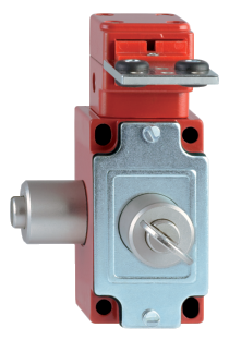
Obszar stosowania:
Typoszereg SHGV szczególnie sprawdza się w bardziej złożonych zakładach i ciągach produkcyjnych, do zabezpieczenia oddalonych od siebie i rzadko używanych osłon i drzwiczek serwisowych.
Inne zastosowania to sytuacje w których istnieje ryzyko porażenia prądem, praca w wysokiej temperaturze, praca w skrajnie niekorzystnych warunkach otoczenia oraz w zakładach chemicznych i przetwórczych, w których wymagana jest ochrona przeciwwybuchowa (patrz Urządzenia dla stref EX).
Budowa i zasada działania:
Podstawową cechą funkcjonalną Systemu transferu klucza jest to, że zależnie od stanu systemu sterowania maszyny, klucz jest uwięziony i nie może zostać wyjęty albo w trybie automatycznym (osłona zaryglowana) w urządzeniu sterowniczym (np. przełącznik w formie stacyjki z kluczem) lub, w urządzeniu ryglującym osłonę, w stacyjce blokady bezpieczeństwa, gdy osłona jest otwarta (a zasilanie maszyny wyłączone).
Reasumując, kluczyk jest uwięziony albo w urządzeniu ryglującym osłonę bezpieczeństwa, albo w stacyjce na pulpicie sterowniczym.
Typoszereg SHGV, SVE, SVM
Grupa produktów „Bezpieczne wyłączanie i monitorowanie" obejmuje kompleksowy asortyment urządzeń bezpieczeństwa do monitorowania położenia drzwi ochronnych i bezdotykowego zabezpieczania niebezpiecznych miejsc i stref zagrożeń. Oferta obejmuje m.in. przyciski zatrzymania awaryjnego, wyłączniki pozycyjne z funkcją bezpieczeństwa, wyłączniki bezpieczeństwa i wyłączniki nożne bezpieczeństwa. Ponadto Schmersal oferuje zapory świetlne, kurtyny świetlne i wielopromieniowe bariery świetlne bezpieczeństwa.
.png?id=d0ac8913a0bfcc62dbb2d1f75aa8fbce)
