MZM 100 ST2-1P2P-A Test
MZM 100 ST2-1P2P-A Test
- Guard locking monitored
- Power to lock
- Connector M12, 8-pole
- Automatic latching
- Solenoid interlocks with innovating and unique operating principle
- 40 mm x 179 mm x 40 mm
- Electronic contact-free, coded system
- Thermoplastic enclosure
- Max. length of the sensor chain 200 m
- 3 LEDs to show operating conditions
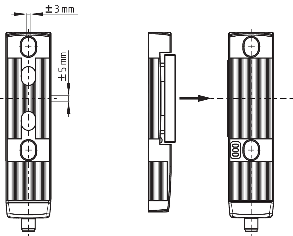
- Sensor technology permits an offset between actuator and interlock of ± 5 mm vertically and ± 3 mm horizontally
- Intelligent diagnosis
- Self-monitoring series-wiring
- Patented
Ordering data
| Note (Delivery capacity) |
Not available! |
| Product type description |
MZM 100 ST2-1P2P-A Test |
| Article number (order number) |
999999910 |
| EAN (European Article Number) |
4030661394787 |
| eCl@ss number, version 12.0 |
27-27-26-03 |
| eCl@ss number, version 11.0 |
27-27-26-03 |
| eCl@ss number, version 9.0 |
27-27-26-03 |
| ETIM number, version 7.0 |
EC002593 |
| ETIM number, version 6.0 |
EC002593 |
General data
| Standards |
EN ISO 13849-1 EN ISO 14119 EN IEC 60947-5-3 EN IEC 61508 |
| Coding |
Universal coding |
| Coding level according to EN ISO 14119 |
Low |
| Working principle |
inductive |
| Housing material |
Plastic, glass-fibre reinforced thermoplastic, self-extinguishing |
| Reaction time, maximum |
150 ms |
| Duration of risk, maximum |
150 ms |
| Gross weight |
698 g |
General data - Features
| Power to lock |
Yes |
| Solenoid interlock monitored |
Yes |
| Short circuit detection |
Yes |
| Cross-circuit detection |
Yes |
| Series-wiring |
Yes |
| Safety functions |
Yes |
| Integral system diagnostics, status |
Yes |
| Number of safety contacts |
2 |
| Safety classification |
| Vorschriften |
EN ISO 13849-1 EN IEC 61508 |
Safety classification - Interlocking function
| Performance Level, up to |
e |
| Category |
4 |
| PFH value |
3.54 x 10⁻⁹ /h |
| Safety Integrity Level (SIL), suitable for applications in |
3 |
| Mission time |
20 Year(s) |
Mechanical data
| Mechanical life, minimum |
1,000,000 Operations |
| Note (Mechanical life) |
Actuating speed ≤ 0.5 m/s Operations for door weights ≤ 5 kg |
| Holding force, typically |
750 N |
| Holding force, guaranteed |
500 N |
| Type of the fixing screws |
2x M6 |
| Tightening torque of the fixing screws |
8 Nm |
Mechanical data - Switching distances
| Assured switching distance "ON" Sao |
0 mm |
| Assured switching distance "OFF" Sar |
1 mm |
| Note (switching distance) |
All switching distances in accordance EN IEC 60947-5-3 |
Mechanical data - Connection technique
| Length of sensor chain, maximum |
200 m |
| Note (length of the sensor chain) |
Cable length and cross-section change the voltage drop dependiing on the output current |
| Note (series-wiring) |
Unlimited number of devices, oberserve external line fusing, max. 31 devices in case of serial diagnostic SD |
| Termination |
Connector M12, 8-pole |
Mechanical data - Dimensions
| Length of sensor |
40 mm |
| Width of sensor |
40 mm |
| Height of sensor |
177.5 mm |
Ambient conditions
| Degree of protection |
IP65 IP67 |
| Ambient temperature |
-25 ... +55 °C |
| Storage and transport temperature |
-25 ... +70 °C |
| Relative humidity, minimum |
30 % |
| Relative humidity, maximum |
95 % |
| Note (Relative humidity) |
non-condensing non-icing |
| Resistance to vibrations |
10 … 150 Hz, amplitude 0.35 mm / 5 g |
| Restistance to shock |
30 g / 11 ms |
| Protection class |
III |
| Permissible installation altitude above sea level, maximum |
2,000 m |
Ambient conditions - Insulation values
| Rated insulation voltage Ui |
32 VDC |
| Rated impulse withstand voltage Uimp |
0.8 kV |
| Overvoltage category |
III |
| Degree of pollution |
3 |
Electrical data
| Operating voltage |
24 VDC -15 % / +10 % (stabilised PELV power supply) |
| No-load supply current I0, typical |
100 mA |
| Current consumption with magnet ON, average |
350 mA |
| Current consumption with magnet ON, peak |
550 mA / 10 ms |
| Rated operating voltage |
24 VDC |
| Operating current |
1,100 mA |
| Required rated short-circuit current |
100 A |
| External wire and device fuse rating |
2 A gG |
| Time to readiness, maximum |
4,000 ms |
| Switching frequency, maximum |
1 Hz |
Electrical data - Magnet control
| Designation, Magnet control |
IN |
| Switching thresholds |
-3 V … 5 V (Low) 15 V … 30 V (High) |
| Current consumption at 24 V |
10 mA |
| Magnet switch-on time |
100 % |
| Test pulse duration, maximum |
5 ms |
| Test pulse interval, minimum |
40 ms |
| Classification ZVEI CB24I, Sink |
C0 |
| Classification ZVEI CB24I, Source |
C1 C2 C3 |
Electrical data - Safety digital inputs
| Designation, Safety inputs |
X1 and X2 |
| Switching thresholds |
−3 V … 5 V (Low) 15 V … 30 V (High) |
| Current consumption at 24 V |
5 mA |
| Test pulse duration, maximum |
1 ms |
| Test pulse interval, minimum |
100 ms |
| Classification ZVEI CB24I, Sink |
C1 |
| Classification ZVEI CB24I, Source |
C1 C2 C3 |
Electrical data - Safety digital outputs
| Designation, Safety outputs |
Y1 and Y2 |
| Rated operating current (safety outputs) |
250 mA |
| Design of control elements |
short-circuit proof, p-type |
| Voltage drop Ud, maximum |
1 V |
| Leakage current Ir, maximum |
0.5 mA |
| Voltage, Utilisation category DC-13 |
24 VDC |
| Current, Utilisation category DC-13 |
0.25 A |
| Test pulse interval, typical |
1000 ms |
| Test pulse duration, maximum |
1 ms |
| Classification ZVEI CB24I, Source |
C1 |
| Classification ZVEI CB24I, Sink |
C1 |
Electrical data - Diagnostic outputs
| Designation, Diagnostic outputs |
OUT |
| Design of control elements |
short-circuit proof, p-type |
| Voltage drop Ud, maximum |
2 V |
| Voltage, Utilisation category DC-13 |
24 VDC |
| Current, Utilisation category DC-13 |
0.05 A |
Status indication
| Note (LED switching conditions display) |
Operating condition: LED green Error / functional defect: LED red Supply voltage UB: LED green |
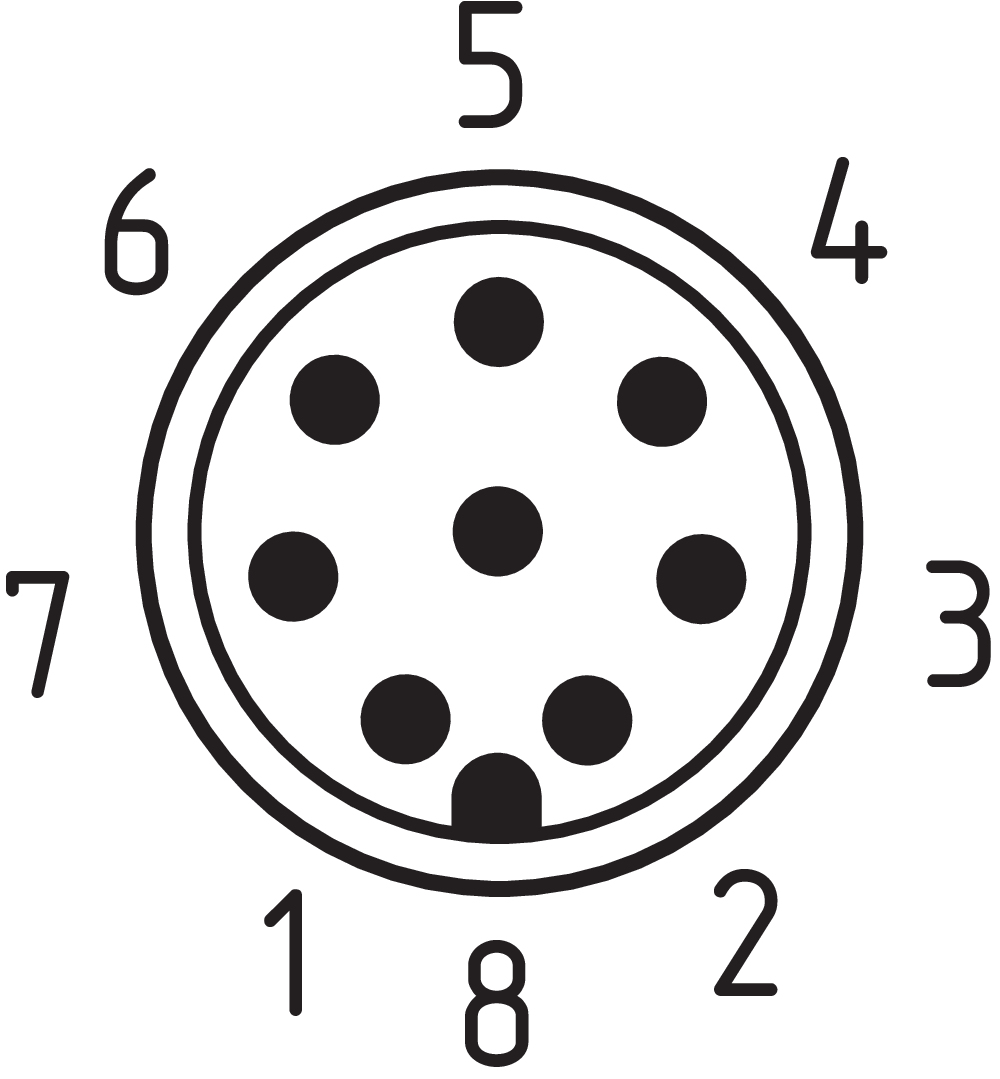
Pin assignment
| PIN 1 |
A1 Supply voltage UB |
| PIN 2 |
X1 Safety input 1 |
| PIN 3 |
A2 GND |
| PIN 4 |
Y1 Safety output 1 |
| PIN 5 |
OUT Diagnostic output |
| PIN 6 |
X2 Safety input 2 |
| PIN 7 |
Y2 Safety output 2 |
| PIN 8 |
IN Solenoid control |
Scope of delivery
| Scope of delivery |
Actuator must be ordered separately. |
Accessory
| Recommendation (actuator) |
MZM 100-B1.1 |
Note
| Note (General) |
As long as the actuating unit is applied to the solenoid interlock, the unlocked safety guard can be relocked. In this case, the safety outputs are re-enabled, so that the safety guard must not be opened. |
Language filter
Datasheet
Operating instructions and Declaration of conformity
SISTEMA-VDMA library
Download the latest version of Adobe Reader
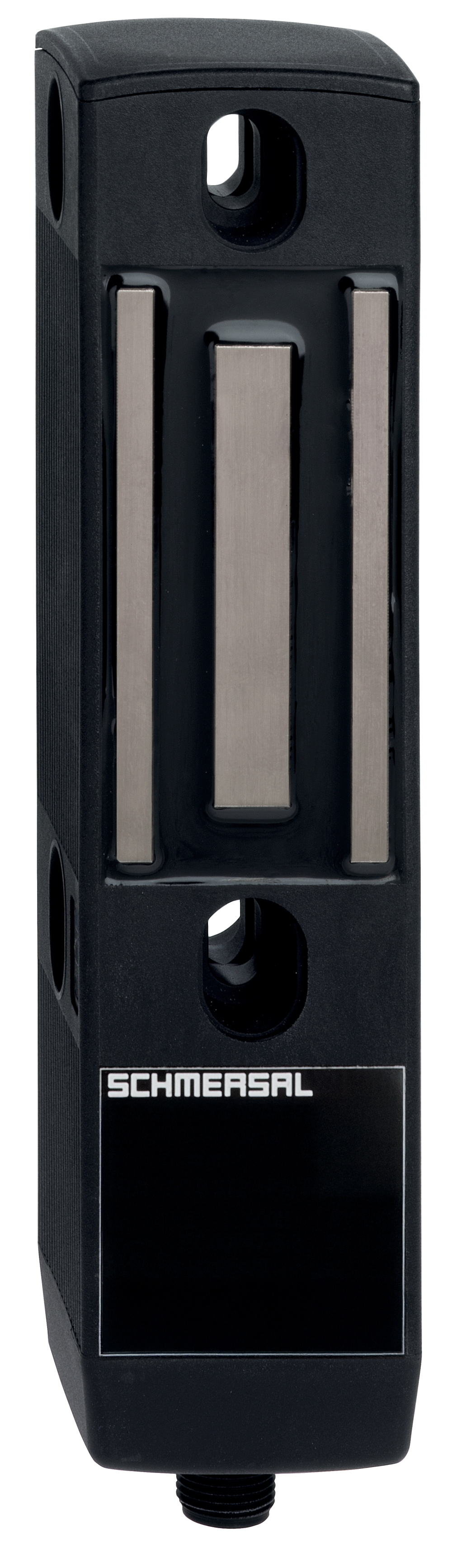
Product picture (catalogue individual photo)
Dimensional drawing basic component
Dimensional drawing miscellaneous
Contact arrangement
Wiring example
Table of Contents
- 1 About this document
- 1.1 Function
- 1.2 Target group of the operating instructions: authorised qualified personnel
- 1.3 Explanation of the symbols used
- 1.4 Appropriate use
- 1.5 General safety instructions
- 1.6 Warning about misuse
- 1.7 Exclusion of liability
- 2 Product description
- 2.1 Ordering code
- 2.2 Special versions
- 2.3 Purpose
- 2.4 Technical Data
- 3 Mounting
- 3.1 General mounting instructions
- 3.2 Dimensions
- 4 Electrical connection
- 4.1 General information for electrical connection
- 4.2 Serial diagnostic -SD
- 4.3 Wiring examples for series-wiring
- 4.4 Wiring configuration and connector accessories
- 5 Operating principles and latching force adjustment
- 5.1 Mode of operation of the safety outputs
- 5.2 Description of the latching force adjustment
- 6 Diagnostic functions
- 6.1 Diagnostic-LEDs
- 6.2 Solenoid interlock with conventional diagnostic output
- 6.3 Solenoid interlock with serial diagnostic function SD
- 7 Set-up and maintenance
- 7.1 Functional testing
- 7.2 Maintenance
- 8 Disassembly and disposal
- 8.1 Disassembly
- 8.2 Disposal
1 About this document
1.1 Function
This document provides all the information you need for the mounting, set-up and commissioning to ensure the safe operation and disassembly of the switchgear. The operating instructions enclosed with the device must always be kept in a legible condition and accessible.
1.2 Target group of the operating instructions: authorised qualified personnel
All operations described in the operating instructions manual must be carried out by trained specialist personnel, authorised by the plant operator only.
Please make sure that you have read and understood these operating instructions and that you know all applicable legislations regarding occupational safety and accident prevention prior to installation and putting the component into operation.
The machine builder must carefully select the harmonised standards to be complied with as well as other technical specifications for the selection, mounting and integration of the components.
1.3 Explanation of the symbols used
- Information, hint, note: This symbol is used for identifying useful additional information.
- Caution: Failure to comply with this warning notice could lead to failures or malfunctions.
Warning: Failure to comply with this warning notice could lead to physical injury and/or damage to the machine.
1.4 Appropriate use
The Schmersal range of products is not intended for private consumers.
The products described in these operating instructions are developed to execute safety-related functions as part of an entire plant or machine. It is the responsibility of the manufacturer of a machine or plant to ensure the correct functionality of the entire machine or plant.
The safety switchgear must be exclusively used in accordance with the versions listed below or for the applications authorised by the manufacturer. Detailed information regarding the range of applications can be found in the chapter "Product description".
1.5 General safety instructions
The user must observe the safety instructions in this operating instructions manual, the country specific installation standards as well as all prevailing safety regulations and accident prevention rules.
- Further technical information can be found in the Schmersal catalogues or in the online catalogue on the Internet: products.schmersal.com.
The information contained in this operating instructions manual is provided without liability and is subject to technical modifications.
There are no residual risks, provided that the safety instructions as well as the instructions regarding mounting, commissioning, operation and maintenance are observed.
1.6 Warning about misuse
- In case of inadequate or improper use or manipulations of the component, personal hazards or damage to machinery or plant components cannot be excluded.
1.7 Exclusion of liability
We shall accept no liability for damages and malfunctions resulting from defective mounting or failure to comply with the operating instructions manual. The manufacturer shall accept no liability for damages resulting from the use of unauthorised spare parts or accessories.
For safety reasons, invasive work on the device as well as arbitrary repairs, conversions and modifications to the device are strictly forbidden, the manufacturer shall accept no liability for damages resulting from such invasive work, arbitrary repairs, conversions and/or modifications to the device.
2 Product description
2.1 Ordering code
| Product type description: MZM 100 (1) (2)-(3)(4)(5)-A |
| (1) | |
| without | Guard locking monitored > |
| B | Actuator monitored |
| (2) | |
| ST | Connector plug M23, 8+1-pole |
| ST2 | Connector plug M12, 8-pole |
| (3) | |
| 1P2P | 1 p-type diagnostic output and 2 p-type safety outputs (only in connection with "Solenoid interlock monitored") |
| 1P2PW | Similar to -1P2P, combined diagnostic signal: guard door closed and solenoid interlock locked (only in connection with "Solenoid interlock monitored") |
| 1P2PW2 | Similar to -1P2P, combined diagnostic signal: guard door closed and can be locked (only in connection with "Actuator monitored") |
| SD2P | serial diagnostic output and 2 p-type safety outputs |
| (4) | |
| without | without latching (only in connection with "Solenoid interlock monitored") |
| R | electrical latching force, typically 30 N |
| RE | adjustable latching force, typically 30 … 100 N |
| (5) | |
| M | permanent magnet, typically 15 N |
2.2 Special versions
For special versions, which are not listed in the ordering code, these specifications apply accordingly, provided that they correspond to the standard version.
2.3 Purpose
- The safety switchgears are classified according to EN ISO 14119 as type 4 interlocking devices.
The MZM 100 is designed for application in safety circuits and is used for monitoring the position of movable separating safety guards. A door detection sensor monitors the closed condition of the safety guard. The optional variable latching force is activated by the detection of the actuator when the safety guard is closed. The latching force exercised by the permanent magnet keeps the safety guard closed, also in de-energised condition (approx. 15 N).
The different variants can be used as safety switch with interlocking function either as solenoid interlock.
- If the risk analysis indicates the use of a monitored interlock then a variant with the monitored interlock is to be used, marked with the > symbol in the ordering code.
The actuator monitoring variant (B) is a safety switch with an interlock function for process protection.
The safety function of MZM 100 variant "Solenoid interlock monitored" consists of safely monitoring a magnetic interlocking force for a safety guard, safely switching off the safety outputs when the magnetic force drops below a defined magnetic force and maintaining the safe switched off condition of the safety outputs for as long as the safety guard is open or unlocked.
The safety function of MZM 100 B variant "Actuator monitored" consists of safely switching off the safety outputs when the safety guard is opened and maintaining the safe switched off condition of the safety outputs for as long as the safety guard is open.
- Interlocks with power to lock principle may only be used in special cases after a thorough evaluation of the accident risk, since the safety guard can be opened immediately on failure of the power supply or upon activation of the main switch.
Series-wiring
Series-wiring can be set up. In the case of a series connection, the risk time remains unchanged and the reaction time increases by the sum of the reaction time of the inputs per additional unit specified in the technical data. The quantity of devices is only limited by the cable drops and the external cable fuse protection, according to the technical data.
In devices with the serial diagnostics function (ordering suffix -SD), the serial diagnostics connections are wired in series and connected to a SD-Gateway for evaluation purposes. Up to 31 components can be wired in series.
- The user must evaluate and design the safety chain in accordance with the relevant standards and the required safety level. If multiple safety sensors are involved in the same safety function, the PFH values of the individual components must be added.
- The entire concept of the control system, in which the safety component is integrated, must be validated to the relevant standards.
2.4 Technical Data
General data
| Standards |
EN ISO 13849-1 EN ISO 14119 EN IEC 60947-5-3 EN IEC 61508 |
| Coding |
Universal coding |
| Coding level according to EN ISO 14119 |
Low |
| Working principle |
inductive |
| Housing material |
Plastic, glass-fibre reinforced thermoplastic, self-extinguishing |
| Reaction time, maximum |
150 ms |
| Duration of risk, maximum |
150 ms |
| Gross weight |
698 g |
General data - Features
| Power to lock |
Yes |
| Solenoid interlock monitored |
Yes |
| Short circuit detection |
Yes |
| Cross-circuit detection |
Yes |
| Series-wiring |
Yes |
| Safety functions |
Yes |
| Integral system diagnostics, status |
Yes |
| Number of safety contacts |
2 |
| Safety classification |
| Vorschriften |
EN ISO 13849-1 EN IEC 61508 |
Safety classification - Interlocking function
| Performance Level, up to |
e |
| Category |
4 |
| PFH value |
3.54 x 10⁻⁹ /h |
| Safety Integrity Level (SIL), suitable for applications in |
3 |
| Mission time |
20 Year(s) |
Mechanical data
| Mechanical life, minimum |
1,000,000 Operations |
| Note (Mechanical life) |
Actuating speed ≤ 0.5 m/s Operations for door weights ≤ 5 kg |
| Holding force, typically |
750 N |
| Holding force, guaranteed |
500 N |
| Type of the fixing screws |
2x M6 |
| Tightening torque of the fixing screws |
8 Nm |
Mechanical data - Switching distances
| Assured switching distance "ON" Sao |
0 mm |
| Assured switching distance "OFF" Sar |
1 mm |
| Note (switching distance) |
All switching distances in accordance EN IEC 60947-5-3 |
Mechanical data - Connection technique
| Length of sensor chain, maximum |
200 m |
| Note (length of the sensor chain) |
Cable length and cross-section change the voltage drop dependiing on the output current |
| Note (series-wiring) |
Unlimited number of devices, oberserve external line fusing, max. 31 devices in case of serial diagnostic SD |
| Termination |
Connector M12, 8-pole |
Mechanical data - Dimensions
| Length of sensor |
40 mm |
| Width of sensor |
40 mm |
| Height of sensor |
177.5 mm |
Ambient conditions
| Degree of protection |
IP65 IP67 |
| Ambient temperature |
-25 ... +55 °C |
| Storage and transport temperature |
-25 ... +70 °C |
| Relative humidity, minimum |
30 % |
| Relative humidity, maximum |
95 % |
| Note (Relative humidity) |
non-condensing non-icing |
| Resistance to vibrations |
10 … 150 Hz, amplitude 0.35 mm / 5 g |
| Restistance to shock |
30 g / 11 ms |
| Protection class |
III |
| Permissible installation altitude above sea level, maximum |
2,000 m |
Ambient conditions - Insulation values
| Rated insulation voltage Ui |
32 VDC |
| Rated impulse withstand voltage Uimp |
0.8 kV |
| Overvoltage category |
III |
| Degree of pollution |
3 |
Electrical data
| Operating voltage |
24 VDC -15 % / +10 % (stabilised PELV power supply) |
| No-load supply current I0, typical |
100 mA |
| Current consumption with magnet ON, average |
350 mA |
| Current consumption with magnet ON, peak |
550 mA / 10 ms |
| Rated operating voltage |
24 VDC |
| Operating current |
1,100 mA |
| Required rated short-circuit current |
100 A |
| External wire and device fuse rating |
2 A gG |
| Time to readiness, maximum |
4,000 ms |
| Switching frequency, maximum |
1 Hz |
Electrical data - Magnet control
| Designation, Magnet control |
IN |
| Switching thresholds |
-3 V … 5 V (Low) 15 V … 30 V (High) |
| Current consumption at 24 V |
10 mA |
| Magnet switch-on time |
100 % |
| Test pulse duration, maximum |
5 ms |
| Test pulse interval, minimum |
40 ms |
| Classification ZVEI CB24I, Sink |
C0 |
| Classification ZVEI CB24I, Source |
C1 C2 C3 |
Electrical data - Safety digital inputs
| Designation, Safety inputs |
X1 and X2 |
| Switching thresholds |
−3 V … 5 V (Low) 15 V … 30 V (High) |
| Current consumption at 24 V |
5 mA |
| Test pulse duration, maximum |
1 ms |
| Test pulse interval, minimum |
100 ms |
| Classification ZVEI CB24I, Sink |
C1 |
| Classification ZVEI CB24I, Source |
C1 C2 C3 |
Electrical data - Safety digital outputs
| Designation, Safety outputs |
Y1 and Y2 |
| Rated operating current (safety outputs) |
250 mA |
| Design of control elements |
short-circuit proof, p-type |
| Voltage drop Ud, maximum |
1 V |
| Leakage current Ir, maximum |
0.5 mA |
| Voltage, Utilisation category DC-13 |
24 VDC |
| Current, Utilisation category DC-13 |
0.25 A |
| Test pulse interval, typical |
1000 ms |
| Test pulse duration, maximum |
1 ms |
| Classification ZVEI CB24I, Source |
C1 |
| Classification ZVEI CB24I, Sink |
C1 |
Electrical data - Diagnostic outputs
| Designation, Diagnostic outputs |
OUT |
| Design of control elements |
short-circuit proof, p-type |
| Voltage drop Ud, maximum |
2 V |
| Voltage, Utilisation category DC-13 |
24 VDC |
| Current, Utilisation category DC-13 |
0.05 A |
Status indication
| Note (LED switching conditions display) |
Operating condition: LED green Error / functional defect: LED red Supply voltage UB: LED green |
Pin assignment
| PIN 1 |
A1 Supply voltage UB |
| PIN 2 |
X1 Safety input 1 |
| PIN 3 |
A2 GND |
| PIN 4 |
Y1 Safety output 1 |
| PIN 5 |
OUT Diagnostic output |
| PIN 6 |
X2 Safety input 2 |
| PIN 7 |
Y2 Safety output 2 |
| PIN 8 |
IN Solenoid control |
UL notice
- Use isolated power supply only. If the cable and connector assembly is not listed for Type 12 or higher, then the device shall be used in a Type 1 environment only.
3 Mounting
3.1 General mounting instructions
- Please observe the remarks of the standards EN ISO 12100, EN ISO 14119 and EN ISO 14120.
- The solenoid interlock must be used as an end stop.
Any mounting position. The system must only be operated with an angle of ≤ 2° between the solenoid interlock and the actuator.
For fitting the solenoid interlock and the actuator, two mounting holes for M6 screws with washers (washers included in delivery) are provided.
After fitting, the mounting holes can be sealed by means of the supplied plugs. The plugs serve as a means of sealing the assembly openings and are also suitable to prevent against tampering with the screw connection.
Minimum distance between two devices: 100 mm
- The actuator must be permanently fitted to the safety guards and protected against displacement by suitable measures (tamperproof screws, gluing, drilling of the screw heads).
- At an ambient temperature of ≥ 50 °C, the safety component must be fitted so that it is protected against unintentional contact with persons.
- The safety component must be operated in the operating direction of the latching force (refer to image).
Axial misalignment and operating direction of the latching force

3.2 Dimensions
All measurements in mm.
Solenoid interlock
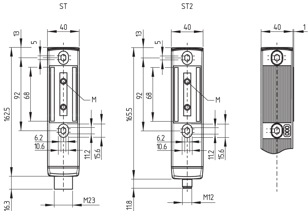
Actuator

Legend
M permanent magnet
4 Electrical connection
4.1 General information for electrical connection
- The electrical connection may only be carried out by authorised personnel in a de-energised condition.
The power supply must have protection against permanent overvoltage. Supply units according to EN 60204-1 is recommended.
The required electrical cable fuse protection must be integrated in the installation.
The safety outputs can be integrated into the safety circuit of the control system.
Requirements for the connected safety-monitoring module:
Dual-channel safety input, suitable for 2 p-type semi-conductor outputs
- Configuration of the safety-monitoring module
If the safety sensor is connected to electronic safety-monitoring modules, we recommend that you set a discrepancy time of min. 100 ms. The safety inputs of the safety-monitoring module must be able blanking a test impulse of approx. 1 ms. The safety-monitoring module does not need to have a cross-wire short monitoring function, if necessary, the cross-wire short monitoring function must be disabled.
- Information for the selection of suitable safety-monitoring modules can be found in the Schmersal catalogues or in the online catalogue on the Internet: products.schmersal.com
4.2 Serial diagnostic -SD
Cable design
The wiring capacity of the connecting cable of the solenoid interlock must not exceed 50 nF. Depending on the strand structure, normal unshielded 30 m long control cables LIYY 0.25 mm² to 1.5 mm² have a wiring capacitance of approx. 3 … 7 nF.
- On wiring SD devices, please pay attention to the voltage drop on the cables and the current carrying capacity of the individual components.
- Accessories for the series-wiring
For convenient wiring and series-wiring of SD components, the SD junction boxes PFB-SD-4M12-SD (variant for the field) and PDM-SD-4CC-SD (variant for control cabinet on carrier rail) are available along with additional comprehensive accessories. Detailed information is available on the Internet, products.schmersal.com.
4.3 Wiring examples for series-wiring
Series-wiring can be set up. In the case of a series connection, the risk time remains unchanged and the reaction time increases by the sum of the reaction time of the inputs per additional unit specified in the technical data. The quantity of devices is only limited by the cable drops and the external cable fuse protection, according to the technical data. Series-wiring of up to 31 MZM100 … SD components with serial diagnostics is possible.
The application examples shown are suggestions. They however do not release the user from carefully checking whether the switchgear and its set-up are suitable for the individual application. The application examples shown are suggestions.
Wiring example 1: Series-wiring of the MZM 100 with conventional diagnostic output
The voltage is supplied at both safety inputs of the terminal safety component of the chain (considered from the safety-monitoring module).
The safety outputs of the first safety component are wired to the safety-monitoring module.
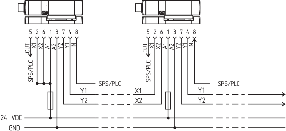
Y1 and Y2 = Safety outputs → Safety monitoring module
Wiring example 2: series-wiring of the MZM 100 with serial diagnostic function
In devices with the serial diagnostics function (ordering suffix -SD), the serial diagnostics connections are wired in series and connected to a SD-Gateway for evaluation purposes. The safety outputs of the first safety component are wired to the safety-monitoring module. The serial Diagnostic Gateway is connected to the serial diagnostic input of the first safety component.

Y1 and Y2 = Safety outputs → Safety monitoring module
SD-IN → Gateway → Field bus
4.4 Wiring configuration and connector accessories
| Function safety switchgear | Pin configuration of the connector | Conductor numbering or colour code of the Schmersal connector plugs | Poss. Colour code of other commercially available connector plugs according to EN 60947-5-2 | |||
|---|---|---|---|---|---|---|
| With conventional diagnostic output | with serial diagnostic function | M23, IP67 | M12, IP67 / IP69 to DIN 47100 | |||
| A1 | Ue | 1 | 1 | WH | BN | |
| X1 | Safety input 1 | 2 | 2 | BN | WH | |
| A2 | GND | 3 | 3 | GN | BU | |
| Y1 | Safety output 1 | 4 | 4 | YE | BK | |
| OUT | Diagnostic output | SD output | 5 | 5 | GY | GY |
| X2 | Safety input 2 | 6 | 6 | PK | PK | |
| Y2 | Safety output 2 | 7 | 7 | BU | VT | |
| IN | Magnet control | SD input | 8 | 8 | RD | OR |
| without function | 9 | |||||
| Connector plug ST M23, (8+1)-pole | |
|---|---|
 | |
| Pre-wired cables with socket (female) IP67, M23, (8+1)-pin - 8 x 0.75 mm² | |
| Cable length | Ordering code |
| 5.0 m | 101209959 |
| 10.0 m | 101209958 |
| Connector plug with plug (female)IP67, M23, (8+1)-pin - 8 x 0.75 mm² | |
| Implementation | Ordering code |
| with soldering terminals | 101209970 |
| with crimp terminals | 101209994 |
| Connector plug ST2 M12, 8-pole | |
|---|---|
 | |
| Connecting cables with coupling (female) IP67 / IP69, M12, 8-pin - 8 x 0.25 mm² to DIN 47100 | |
| Cable length | Ordering code |
| 2.5 m | 103011415 |
| 5.0 m | 103007358 |
| 10.0 m | 103007359 |
| 15.0 m | 103011414 |
5 Operating principles and latching force adjustment
5.1 Mode of operation of the safety outputs
The safety outputs are released when the following conditions are met:
- the actuator has been detected and
- the interlock is locked, the magnetic force is > 500 N
The unlocking of the solenoid interlock causes the safety outputs to be disabled within the risk time. As long as the actuator is present on the solenoid interlock, the unlocked solenoid interlock can be locked again. In that case, the safety outputs are re-enabled.
The latching force F is permanently measured and checked. In this way, soiling of the solenoid interlock can be detected. If the latching force drops below 500 N, the release signal for the safety outputs Y1 / Y2 is not given.
Actuator-monitored version MZM 100 B:
The safety outputs are released when the following conditions are met:
- the actuator has been detected, the latching force is active and
- locking with magnetic force > 500 N possible
Due to the permanent monitoring of the closed magnetic circuit, the safety outputs Y1/Y2 are only enabled during the latching, when the magnetic circuit is properly closed and the latching force can also be obtained when activated. If the metal surfaces are soiled or damaged, the enabling signal is not transmitted.
The unlocking of the MZM 100 B does not lead to a switch-off.
- Forcible separation of solenoid interlock and actuator (only with "interlock-monitored" version)
The solenoid interlock has a clamping force "F" of 500 N. When the actuator and the interlock are separated in an unauthorised and forced way, the safety guard is opened and the enabling paths are switched off within 150 ms. This is signalled through the yellow and red LED blinking alternatively. To bring the system back in operational condition, the safety guard needs to be closed first and the magnet control must be switched off and back on (Pin 8); the yellow and red LED now are blinking simultaneously. With the safety guard closed, an anti-tampering period of 10 minutes must be waited until the LEDs go out. Now, the system is operational again after the solenoid control has been switched off and back on (Pin 8). (The actuator nor the solenoid interlock are damaged)
5.2 Description of the latching force adjustment
The latching force of the MZM 100 with ordering suffix -RE can be set in 8 steps of approx. 10 N each within a range of approx. 30 N to approx. 100 N. To this end, the MZM 100 TARGET is used directly on the fitted MZM 100.
Latching force adjustment for the MZM 100 with conventional diagnostic output
- Open the safety guard and isolate the MZM 100 from the voltage supply. Either switch off the voltage supply or pull out the connector.
- Put the adjustment target with the active side on the identification plate of the MZM 100.
- Switch the voltage supply of the MZM 100 back on and wait at least 10 seconds before removing the adjustment target. The component searches for the adjustment target. When the adjustment mode is active, the safety outputs remain disabled.
- Remove the adjustment target again from the component. The yellow LED of the MZM 100 will repeatedly flash briefly to show the currently set latching force level (e.g. 4 flashes = 4th latching force level approx. 60 N).
- Put the adjustment target approx. 1 second back on the solenoid interlock with the safety guard open to gradually increase the latching force by steps of approx. 10 N each. The number of flashes will increase accordingly.
The modified latching force can be checked directly on the safety guard. If necessary, the latching force can be increased by another step. When latching force level 8 is reached, level 1 will be activated when the target is placed back on the component.
- Switch off the voltage supply of the MZM 100 once more to permanently save the chosen latching force.
When the component is switched off, the adjustment mode is quit. After the voltage supply is switched back on, the MZM 100 is ready for operation.
Latching force indication
If the voltage supply of the MZM 100 is switched on when the safety guard is open, the yellow LED will show the set latching force for 10 seconds by means of repeated brief flashes (e.g. 4 flashes = 4th latching force level approx. 60 N). At stage 5, the last code is incomplete (5x flash with a complete or incomplete repeat of 3x flash).
| Flash codes | Latching force RE | Latching force REM |
|---|---|---|
| 1 flash pulse | approx. 30 N | approx. 45 N |
| 2 flash pulses | approx. 40 N | approx. 55 N |
| 3 flash pulses | approx. 50 N | approx. 65 N |
| 4 flash pulses | approx. 60 N | approx. 75 N |
| 5 flash pulses | approx. 70 N | approx. 85 N |
| 6 flash pulses | approx. 80 N | approx. 95 N |
| 7 flash pulses | approx. 90 N | approx. 105 N |
| 8 flash pulses | approx. 100 N | approx. 115 N |
Latching force adjustment for the MZM 100-...-SD with serial diagnostic function
The latching force can be adjusted through the latching force bits 1-3 of the request byte in 8 steps within a range of 30 - 100 N (45 - 115 N with permanent magnet).
| Latching force bit | Latching force RE | Latching force REM | ||
|---|---|---|---|---|
| 3 | 2 | 1 | ||
| 0 | 0 | 0 | approx. 30 N | approx. 45 N |
| 0 | 0 | 1 | approx. 40 N | approx. 55 N |
| 0 | 1 | 0 | approx. 50 N | approx. 65 N |
| 0 | 1 | 1 | approx. 60 N | approx. 75 N |
| 1 | 0 | 0 | approx. 70 N | approx. 85 N |
| 1 | 0 | 1 | approx. 80 N | approx. 95 N |
| 1 | 1 | 0 | approx. 90 N | approx. 105 N |
| 1 | 1 | 1 | approx. 100 N | approx. 115 N |
- The actual latching forces may deviate from the specified values owing to the different influences (e.g. angled position of actuator, contamination or damage to metal surface, etc.).
- When the guard system is opened for the first time from the locked status, higher latching forces may be experienced on account of residual magnetism.
6 Diagnostic functions
6.1 Diagnostic-LEDs
The MZM 100 signals the operational state as well as errors through three coloured LEDs installed on the front side of the device.
| green (Power) | Supply voltage on |
| yellow (Status) | Operating condition |
| red (Fault) | Error (see table 2: Error messages / flash codes red diagnostic LED) |
6.2 Solenoid interlock with conventional diagnostic output
The short-circuit proof diagnostic output OUT can be used for central visualisation or control tasks, e.g. in a PLC.
The diagnostic output is not a safety-related output.
Error
Errors which no longer guarantee the function of the safety switchgear (internal errors) cause the safety outputs to be disabled within the duration of risk. After fault rectification, the error message is reset by opening and re-closing the corresponding safety guard.
Fault warning
A fault that does not immediately endanger the safety function of the safety switchgear (e.g. too high ambient temperature, safety output at external potential, cross-circuit) leads to delayed shutdown (see Table 2). This signal combination, diagnostic output disabled and safety channels still enabled, can be used to stop the production process in a controlled manner. An error warning is deleted when the cause of error is eliminated. If the fault warning remains on for 30 minutes, the safety outputs are also switched off (red LED flashes, see Table 2).
- If more than one fault is detected at the safety outputs, the component will be electronically locked and a normal fault reset will no longer be possible. To reset this type of interlocking, the component must be isolated from the power supply after elimination of the error causes.
Behaviour of the diagnostic outputs of the W and W2 variants
Input signal magnet control

Normal sequence, door was locked

Door could not be locked or fault

 | Lock |  | Unlock |  | Locking time: typically: 100 ... 150 ms, maximum: 1 s |
 | Door open |  | Safety guard closed | ||
 | Safety guard not locked or fault |  | Safety guard locked |
Evaluation of the diagnostic outputs of the W and W2 variants
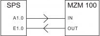
IN = 1 = locking
 | Door can be locked |
 | Door is locked |
Table 1: diagnostic function
The diagnostic output OUT signals faults before the safety outputs are disabled, thus enabling a controlled shutdown.
Diagnostic function of MZM 100 variant "Solenoid interlock monitored"
| System condition | Magnet control | LED | Safety outputs | Diagnostic output OUT | |||
|---|---|---|---|---|---|---|---|
| IN | green | red | yellow | Y1, Y2 | -1P2P | -1P2PW | |
| Door open | 0 V | On | Off | Off | 0 V | 0 V | 0 V |
| Safety guard closed, actuator in | 0 V | On | Off | Flashes | 0 V | 24 V | 24 V |
| Safety guard closed and locked | 24 V | On | Off | On | 24 V | 24 V | 24 V |
| Solenoid interlock cannot be locked. Safety guard not correctly closed or magnet soiled | 24 V | On | Off | Flashes | 0 V | 24 V | 0 V |
| Error warning1) Safety guard locked | 24 V | On | Flashes 2) | On | 24 V | 0 V | 0 V |
| Error | 0 V / 24 V | On | Flashes 2) | Off | 0 V | 0 V | 0 V |
| Violent separation of solenoid interlock and actuator3) | 24 V | On | Flashes 2) | Flashes 2) | 0 V | 0 V | 0 V |
| 1) after 30 min -> fault 2) see flash code 3) cf. note in Section 5.1 on resetting the system to its operating state | |||||||
Diagnostic function of MZM 100 B variant "Actuator monitored"
| System condition | Magnet control | LED | Safety outputs | Diagnostic output OUT | ||
|---|---|---|---|---|---|---|
| IN | green | red | yellow | Y1, Y2 | -1P2PW2 | |
| Door open | 0 V | On | Off | Off | 0 V | 0 V |
| Safety guard closed, actuator in, safety guard can be locked | 0 V | On | Off | Flashes | 24 V | 24 V |
| Safety guard closed and locked | 24 V | On | Off | On | 24 V | 24 V |
| Solenoid interlock cannot be locked. Safety guard not correctly closed or magnet soiled | 24 V | On | Off | Off | 0 V | 0 V |
| Error warning1) actuator in | 0 V / 24 V | On | Flashes 2) | flashes/on | 24 V | 0 V |
| Error | 0 V / 24 V | On | Flashes 2) | Off | 0 V | 0 V |
1) after 30 min -> fault 2) see flash code 3) cf. note in Section 5.1 on resetting the system to its operating state | ||||||
6.3 Solenoid interlock with serial diagnostic function SD
Solenoid interlocks with serial diagnostic function have a serial input and output instead of the conventional diagnostic output. If SD devices are wired in series, the safety channels as well as the inputs and outputs of the diagnostic channels are wired in series. The diagnostic data are transmitted through the series-wiring of the inputs and outputs.
Max. 31 safety switchgear with serial diagnostics can be wired in series. For the evaluation of the serial diagnostics line either the SDG-Gateway, the Universal-Gateway SD-I-U-… or PROFIBUS-Gateway SD-I-DP-V0-2 are used. This SD-Gateway is integrated as a slave in an existing field bus system. In this way, the diagnostic signals can be evaluated by means of a PLC. The necessary software for the integration of the SD-Gateway is available for download at products.schmersal.com.
The response data and the diagnostic data are automatically and permanently written in an input byte of the PLC for each safety device in the series-wired chain. The request data for each safety device is transmitted to the component through an output byte of the PLC.
In case of a communication error between the SD-gateway and the safety device, the switching condition of the solenoid interlock is maintained.
Error
Errors which no longer guarantee the function of the safety switchgear (internal errors) cause the safety outputs to be disabled within the duration of risk. The fault is reset, when the cause is eliminated and bit 7 of the request byte changes from 1 to 0 or the safety guard is opened. Faults at the safety outputs are only deleted upon the next release, as the fault rectification cannot be detected sooner.
Fault warning
A fault that does not immediately endanger the safety function of the safety switchgear (e.g. too high ambient temperature, safety output at external potential, cross-circuit) leads to delayed shutdown (see Table 2). This signal combination, diagnostic output disabled and safety channels still enabled, can be used to stop the production process in a controlled manner. An error warning is deleted when the cause of error is eliminated. If the fault warning remains on for 30 minutes, the safety outputs are also switched off (red LED flashes, see Table 2).
Diagnostic error (warning)
If an error (warning) is signalled in the response byte, detailed fault information can be read out.
Table 3: I/O data and diagnostic data
Communication directions:
request byte: from the PLC to the local electronic safety switchgear
response byte: from the local electronic safety switchgear to the PLC
warning/error byte: from the local electronic safety switchgear to the PLC
| The described condition is reached, when Bit = 1 | ||||
|---|---|---|---|---|
| Bit n° | Request byte | Response byte | Diagnostic error warning | Diagnostic error |
| Bit 0: | Magnet in, error reset | Safety output activated | Error output Y1 | Error output Y1 |
| Bit 1: | Latching force bit | Actuator detected | Error output Y2 | Error output Y2 |
| Bit 2: | Latching force bit | Solenoid interlock locked | Cross-wire short | Cross-wire short |
| Bit 3: | Latching force bit | --- | Magnet temperature too high | Magnet temperature too high |
| Bit 4: | --- | Input condition X1 and X2 | Locking blocked or F < 500 N | Incorrect or defective actuator |
| Bit 5: | --- | --- | Internal device error | Internal device error |
| Bit 6: | --- | Error warning | Communication error between the field bus Gateway and the safety switchgear | Violent separation of actuator and solenoid interlock (only in connection with "Solenoid interlock monitored") |
| Bit 7: | Error reset | Error (enabling path switched off) | Operating voltage too low | Operating voltage too low |
Table 4: Function of the visual diagnostic LEDs, the serial status signals and the safety outputs by means of an example
- of MZM 100 variant "Solenoid interlock monitored"
| System condition | LED | Safety outputs | Response byte bit n°: | |||||||||
|---|---|---|---|---|---|---|---|---|---|---|---|---|
| green | red | yellow | Y1, Y2 | 7 | 6 | 5 | 4 | 3 | 2 | 1 | 0 | |
| Door open | On | Off | Off | 0 V | 0 | 0 | 0 | X | 0 | 0 | 0 | 0 |
| Safety guard closed, actuator in | On | Off | Flashes | 0 V | 0 | 0 | 0 | X | 0 | 0 | 1 | 0 |
| Safety guard closed and locked | On | Off | On | 24 V | 0 | 0 | 0 | X | 0 | 1 | 1 | 1 |
| Solenoid interlock cannot be locked. Safety guard not correctly closed or magnet soiled. | On | Off | Flashes | 0 V | 0 | 0 | 0 | X | 0 | 0 | 1 | 0 |
| Error warning1), Safety guard locked | On | Flashes 2) | On | 24 V | 0 | 1 | 0 | X | 0 | 1 | 1 | 1 |
| Error | On | Flashes 2) | Off | 0 V | 1 | 0 | 0 | X | 0 | X | X | 0 |
| 1) after 30 min -> fault | ||||||||||||
- of MZM 100 B variant "Actuator monitored"
| System condition | LED | Safety outputs | Response byte bit n°: | |||||||||
|---|---|---|---|---|---|---|---|---|---|---|---|---|
| green | red | yellow | Y1, Y2 | 7 | 6 | 5 | 4 | 3 | 2 | 1 | 0 | |
| Door open | On | Off | Off | 0 V | 0 | 0 | 0 | X | 0 | 0 | 0 | 0 |
| Safety guard closed, actuator in,safety guard can be locked | On | Off | Flashes | 24 V | 0 | 0 | 0 | X | 0 | 0 | 1 | 0 |
| Safety guard closed and locked | On | Off | On | 24 V | 0 | 0 | 0 | X | 0 | 1 | 1 | 1 |
| Solenoid interlock cannot be locked. Safety guard not correctly closed or magnet soiled. | On | Off | Flashes | 0 V | 0 | 0 | 0 | X | 0 | 0 | 0 | 0 |
| Error warning1), Safety guard locked | On | Flashes 2) | On | 24 V | 0 | 1 | 0 | X | 0 | X | 1 | 1 |
| Error | On | Flashes 2) | Off | 0 V | 1 | 0 | 0 | X | 0 | X | X | 0 |
| 1) after 30 min -> fault | ||||||||||||
7 Set-up and maintenance
7.1 Functional testing
The safety function of the safety components must be tested.
The following conditions must be previously checked and met:
- Check max. axial misalignment of actuator and safety switch.
- Check max. angular misalignment (see “Mounting” part)
- Check the integrity of the cable entry and connections.
- Check the switch enclosure for damages
- Remove soiling
7.2 Maintenance
In the case of correct installation and adequate use, the safety switchgear features maintenance-free functionality. A regular visual inspection and functional test, including the following steps, is recommended:
- Check of the safety function.
- Check fixation of the safety switch and the actuator.
- Check max. axial misalignment of actuator and solenoid interlock.
- Check max. angular misalignment (see “Mounting” part)
- Check the integrity of the cable entry and connections.
- Check the switch enclosure for damages
- Remove particles of dust and soiling.
- Adequate measures must be taken to ensure protection against tampering either to prevent tampering of the safety guard, for instance by means of replacement actuators.
- Damaged or defective components must be replaced.
8 Disassembly and disposal
8.1 Disassembly
The safety switchgear must be disassembled in a de-energised condition only.
8.2 Disposal
- The safety switchgear must be disposed of in an appropriate manner in accordance with the national prescriptions and legislations.
K.A. Schmersal GmbH & Co. KG, Möddinghofe 30, 42279 Wuppertal
The details and data referred to have been carefully checked. Images may diverge from original. Further technical data can be found in the manual. Technical amendments and errors possible.
Generated on: 18/07/2025, 06:41