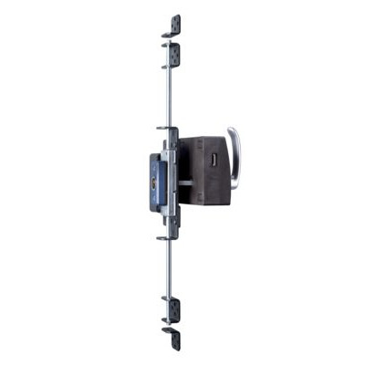
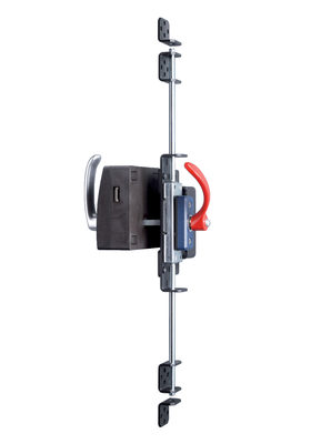
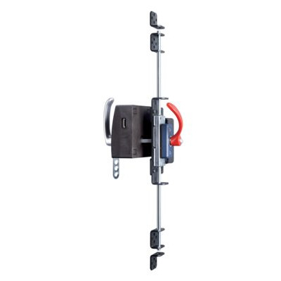
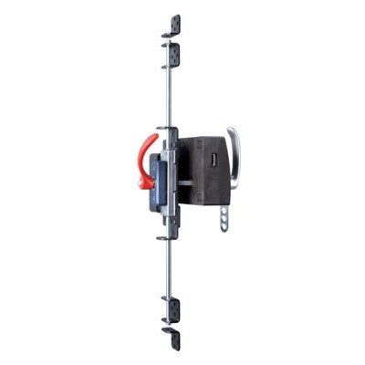
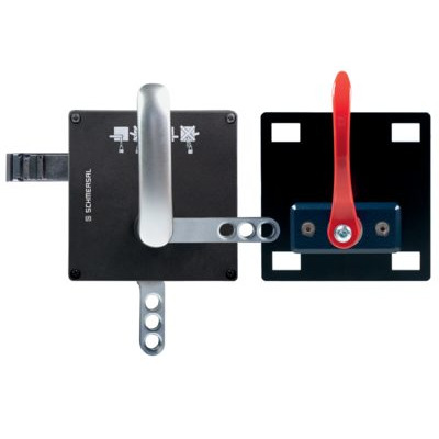
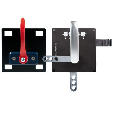
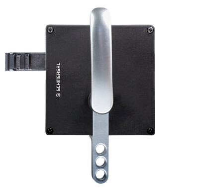
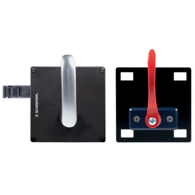
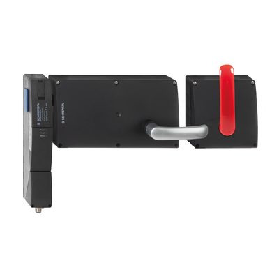
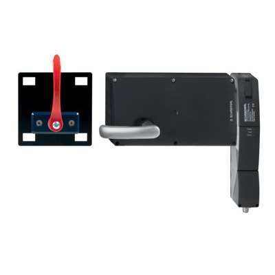
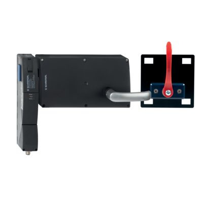
AZM201D-I2-ST2-T-1P2P2P-A
AZM201D-I2-ST2-T-1P2P2P-A
| Product type description: AZM201(1)-(2)-(3)-T-(4)-(5) |
| (1) | |
| Z | Solenoid interlock monitored |
| B | Actuator monitored |
| (2) | |
| without | Standard coding |
| I1 | Individual coding |
| I2 | Individual coding, multiple teaching |
| (3) | |
| SK | Screw terminals |
| CC | Cage clamps |
| ST2 | Connector plug M12, 8-pole |
| (4) | |
| 1P2PW | 1 diagnostic output, p-type and >2 safety outputs, p-type > (combined diagnostic signal: guard system closed and interlock locked) |
| SD2P | serial diagnostic output and 2 p-type safety outputs |
| (5) | |
| without | Power to unlock |
| A | Power to lock |
- Thermoplastic enclosure
- Coding in accordance to ISO 14119 by using RFID-Technology
- 3 LEDs to show operating conditions
- Sensor technology permits an offset between actuator and interlock of ± 5 mm vertically and ± 1,5 mm horizontally
- Suitable for hinged and sliding guards
- Intelligent diagnosis
- Manual release
- Protection class IP66, IP67
- High holding force 2000 N
- 2 OSSD safety outputs for guard door monitoring
- 2 OSSD safety outputs for guard locking monitoring
- symmetrical construction form, assembly on 40mm profiles
- Emergency exit / Emergency release suitable for retrofitting
Ordering data
| Product type description |
AZM201D-I2-ST2-T-1P2P2P-A |
| Article number (order number) |
103042147 |
| EAN (European Article Number) |
4030661559247 |
| eCl@ss number, version 12.0 |
27-27-26-03 |
| eCl@ss number, version 11.0 |
27-27-26-03 |
| eCl@ss number, version 9.0 |
27-27-26-03 |
| ETIM number, version 7.0 |
EC002593 |
| ETIM number, version 6.0 |
EC002593 |
Approvals - Standards
| Certificates |
TÜV cULus FCC IC UKCA ANATEL |
General data
| Standards |
EN IEC 62061 EN ISO 13849-1 EN ISO 14119 EN IEC 60947-5-3 EN IEC 61508 |
| Coding |
Individual coding, multiple teaching |
| Coding level according to EN ISO 14119 |
High |
| Working principle |
RFID |
| Frequency band RFID |
125 kHz |
| Transmitter output RFID, maximum |
-6 dB/m |
| Housing material |
Glass-fibre, reinforced thermoplastic |
| Duration of risk, maximum |
200 ms |
| Reaction time, switching off safety outputs via actuator, maximum |
100 ms |
| Reaction time, switching off safety outputs via safety inputs, maximum |
0.5 ms |
| Gross weight |
495 g |
General data - Features
| Power to lock |
Yes |
| Actuator monitored |
Yes |
| Solenoid interlock monitored |
Yes |
| Manual release |
Yes |
| Short circuit detection |
Yes |
| Safety functions |
Yes |
| Integral system diagnostics, status |
Yes |
| Number of safety contacts |
4 |
| Safety classification |
| Vorschriften |
EN ISO 13849-1 EN IEC 61508 |
Safety classification - Interlocking function
| Performance Level, up to |
e |
| Category |
4 |
| PFH value |
5.70 x 10⁻¹⁰ /h |
| PFD value |
5.00 x 10⁻⁵ |
| Safety Integrity Level (SIL), suitable for applications in |
3 |
| Mission time |
20 Year(s) |
| Safety classification - Interlocking function 2 |
| Performance Level, up to |
d |
| Category |
3 |
| Safety Integrity Level (SIL), suitable for applications in |
2 |
| Mission time |
20 Year(s) |
Safety classification - Guard locking function
| Mission time |
20 Year(s) |
Mechanical data
| Mechanical life, minimum |
1,000,000 Operations |
| Holding force FZh in accordance with EN ISO 14119 |
2,000 N |
| Note (clamping force FZh) |
1,000 N when used with the AZ/AZM201-B30 actuator, for indoor use. |
| Holding force Fmax, maximum |
2,600 N |
| Note (clamping force Fmax) |
1.300 N in Verbindung mit einem Betätiger AZ/AZM201-B30 für Innenanbau. |
| Latching force |
30 N |
| Actuating speed, maximum |
0.2 m/s |
| Type of the fixing screws |
2x M6 |
| Tightening torque of the fastening screws for the housing cover, minimum |
0.7 Nm |
| Tightening torque of the fastening screws for the housing cover, maximum |
1 Nm |
| Note |
Torx T10 |
Mechanical data - Connection technique
| Length of sensor chain, maximum |
200 m |
| Note (length of the sensor chain) |
Cable length and cross-section change the voltage drop dependiing on the output current |
| Note (series-wiring) |
Unlimited number of devices, oberserve external line fusing, max. 31 devices in case of serial diagnostic SD |
| Termination |
Connector M12, 8-pole |
Mechanical data - Dimensions
| Length of sensor |
50 mm |
| Width of sensor |
40 mm |
| Height of sensor |
220 mm |
Ambient conditions
| Degree of protection |
IP66 IP67 |
| Ambient temperature |
-25 ... +60 °C |
| Storage and transport temperature |
-25 ... +85 °C |
| Relative humidity, minimum |
30 % |
| Relative humidity, maximum |
95 % |
| Note (Relative humidity) |
non-condensing |
| Resistance to vibrations |
10 … 150 Hz, amplitude 0.35 mm |
| Restistance to shock |
30 g / 11 ms |
| Protection class |
III |
Ambient conditions - Insulation values
| Rated insulation voltage Ui |
32 VDC |
| Rated impulse withstand voltage Uimp |
0.8 kV |
| Overvoltage category |
III |
| Degree of pollution |
3 |
Electrical data
| Operating voltage |
24 VDC -15 % / +10 % (stabilised PELV power supply) |
| No-load supply current I0, typical |
50 mA |
| Current consumption with magnet ON, peak |
700 mA / 100 ms |
| Rated operating voltage |
24 VDC |
| Operating current |
1,200 mA |
| Required rated short-circuit current |
100 A |
| Time to readiness, maximum |
4,000 ms |
| Switching frequency, maximum |
1 Hz |
Electrical data - Magnet control
| Designation, Magnet control |
IN |
| Switching thresholds |
-3 V … 5 V (Low) 15 V … 30 V (High) |
| Magnet switch-on time |
100 % |
| Test pulse duration, maximum |
5 ms |
| Test pulse interval, minimum |
40 ms |
| Classification ZVEI CB24I, Sink |
C0 |
| Classification ZVEI CB24I, Source |
C1 C2 C3 |
Electrical data - Safety digital inputs
| Switching thresholds |
−3 V … 5 V (Low) 15 V … 30 V (High) |
| Test pulse duration, maximum |
1 ms |
| Test pulse interval, minimum |
100 ms |
| Classification ZVEI CB24I, Sink |
C1 |
| Classification ZVEI CB24I, Source |
C1 C2 C3 |
Electrical data - Safety digital outputs
| Designation, Safety outputs |
Y1 and Y2 |
| Rated operating current (safety outputs) |
250 mA |
| Voltage drop Ud, maximum |
4 V |
| Leakage current Ir, maximum |
0.5 mA |
| Voltage, Utilisation category DC-13 |
24 VDC |
| Current, Utilisation category DC-13 |
0.25 A |
| Note, Utilisation category DC-13 |
Gilt für die Ausgänge Y1 und Y2 |
| Test pulse interval, typical |
1000 ms |
| Test pulse duration, maximum |
0.5 ms |
| Classification ZVEI CB24I, Source |
C2 |
| Classification ZVEI CB24I, Sink |
C1 C2 |
Electrical data - Diagnostic outputs
| Operating current |
100 mA |
| Voltage drop Ud, maximum |
4 V |
| Voltage, Utilisation category DC-13 |
24 VDC |
| Current, Utilisation category DC-13 |
0.05 A |
Status indication
| Note (LED switching conditions display) |
Operating condition: LED green Error / functional defect: LED red Supply voltage UB: LED green |
Pin assignment
| PIN 1 |
A1 Supply voltage UB |
| PIN 2 |
OUT diagnostic output |
| PIN 3 |
A2 GND |
| PIN 4 |
Y1 Safety output 1 |
| PIN 5 |
Y3 safety output 3 |
| PIN 6 |
Y4 safety output Y4 |
| PIN 7 |
Y2 Safety output 2 |
| PIN 8 |
IN Solenoid control |
Scope of delivery
| Scope of delivery |
Actuator must be ordered separately. Triangular key for AZM 201 |
Accessory
| Recommendation (actuator) |
AZ/AZM201-B1 AZ/AZM201-B30 |
Note
| Note (General) |
As long as the actuating unit remains inserted in the solenoid interlock, the unlocked safety guard can be relocked. In this case, the safety outputs are re-enabled, so that the safety guard must not be opened. |
| Note (Actuator monitored) |
Safety outputs Y1, Y2 |
| Note (Solenoid interlock monitored) |
Safety outputs Y3, Y4 |
Language filter
Datasheet
Operating instructions and Declaration of conformity
TÜV certification
UL Certificate
IC-Zertifikat
UKCA certificate
ANATEL certification
Brochure
SISTEMA-VDMA library
Download the latest version of Adobe Reader
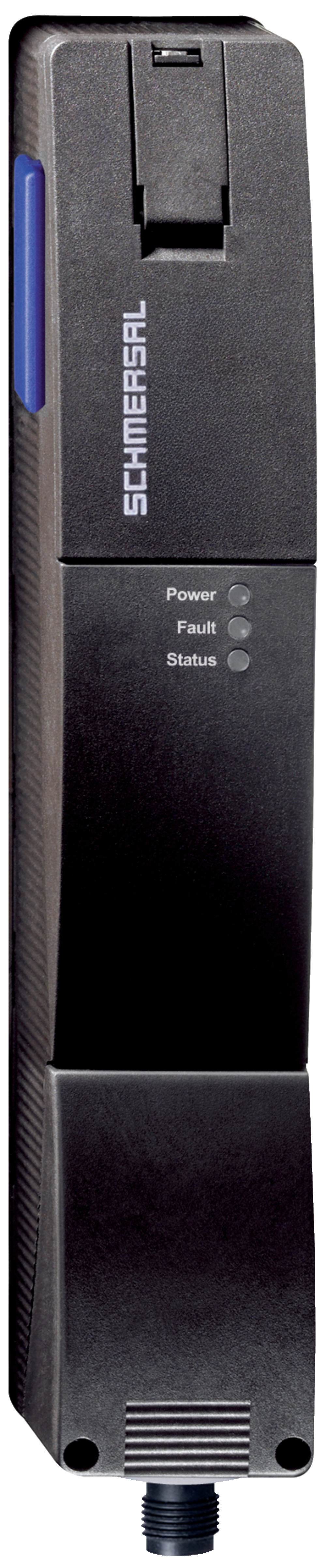
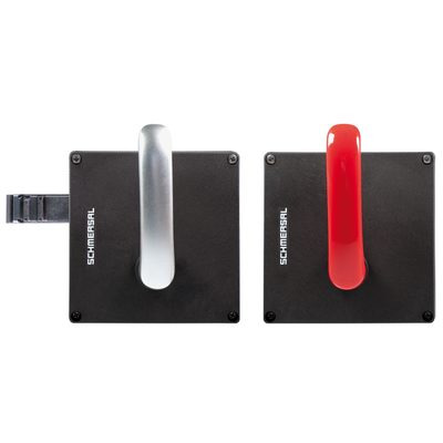
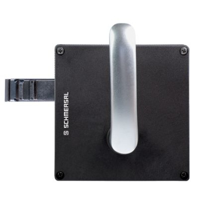
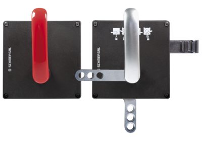
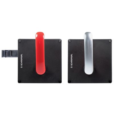
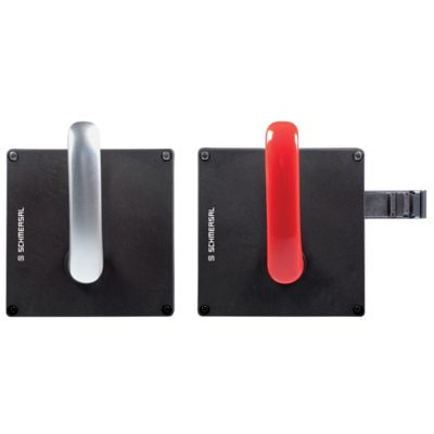
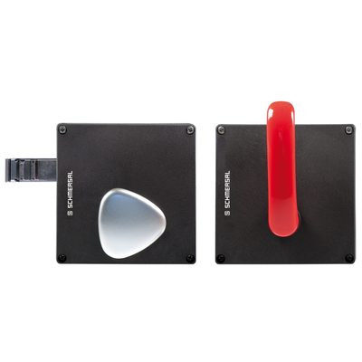
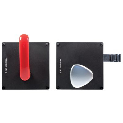
Product picture (catalogue individual photo)
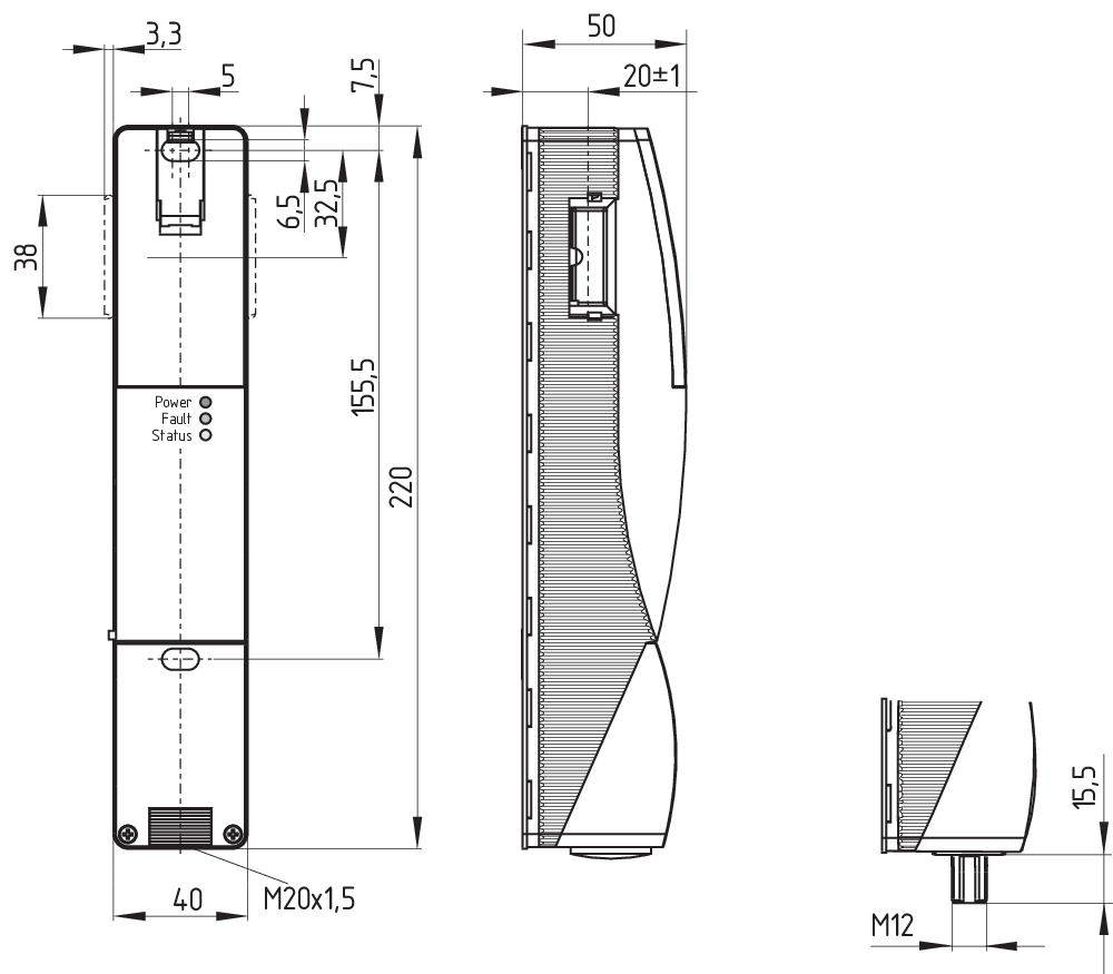
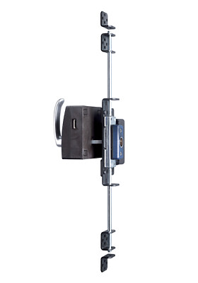
Dimensional drawing basic component

103013493 AZ/AZM201-B1-LT
- for left hinged doors
- Actuators with return spring
- Actuator for sliding guards
- Tolerates up to max. 5 mm overtravel

103013496 AZ/AZM201-B1-LTP0
- for left hinged doors
- with Emergency exit
- Actuators with return spring
- Actuator for sliding guards
- Tolerates up to max. 5 mm overtravel
103013494 AZ/AZM201-B1-RT
- for right hinged doors
- Actuators with return spring
- Actuator for sliding guards
- Tolerates up to max. 5 mm overtravel

103013495 AZ/AZM201-B1-RTP0
- for right hinged doors
- with Emergency exit
- Actuators with return spring
- Actuator for sliding guards
- Tolerates up to max. 5 mm overtravel
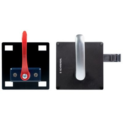
103013499 AZ/AZM201-B30-RTAG1P1-SZ
- for right hinged doors
- with handle and Emergency exit handle
- with integrated lockout tag
- Actuator for hinged guards
- Easy and intuitive operation
- No risk of injury from protruding actuator
- No supplementary door handles required
- Does not protrude into the door opening
103013497 AZ/AZM201-B30-RTAG1P1
- for right hinged doors
- with handle and Emergency exit handle
- Actuator for hinged guards
- Easy and intuitive operation
- No risk of injury from protruding actuator
- No supplementary door handles required
- Does not protrude into the door opening
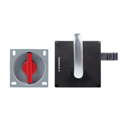
103013502 AZ/AZM201-B30-RTAG1
- for right hinged doors
- with handle
- Actuator for hinged guards
- Easy and intuitive operation
- No risk of injury from protruding actuator
- No supplementary door handles required
- Does not protrude into the door opening
103013500 AZ/AZM201-B30-LTAG1P1-SZ
- for left hinged doors
- with handle and Emergency exit handle
- with integrated lockout tag
- Actuator for hinged guards
- Easy and intuitive operation
- No risk of injury from protruding actuator
- No supplementary door handles required
- Does not protrude into the door opening

103013498 AZ/AZM201-B30-LTAG1P1
- for left hinged doors
- with handle and Emergency exit handle
- Actuator for hinged guards
- Easy and intuitive operation
- No risk of injury from protruding actuator
- No supplementary door handles required
- Does not protrude into the door opening

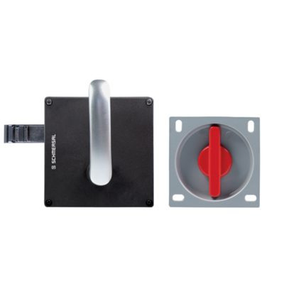
103013501 AZ/AZM201-B30-LTAG1
- for left hinged doors
- with handle
- Actuator for hinged guards
- Easy and intuitive operation
- No risk of injury from protruding actuator
- No supplementary door handles required
- Does not protrude into the door opening
103015820 AZ/AZM201-B30-LTAG1P30
- for left hinged doors
- with handle
- Actuator for hinged guards
- Easy and intuitive operation
- No risk of injury from protruding actuator
- No supplementary door handles required
- Does not protrude into the door opening
103015823 AZ/AZM201-B30-RTAG1P30
- for right hinged doors
- with handle
- Actuator for hinged guards
- Easy and intuitive operation
- No risk of injury from protruding actuator
- No supplementary door handles required
- Does not protrude into the door opening
103015821 AZ/AZM201-B30-LTAG1P31
- for left hinged doors
- with handle and Emergency exit handle
- Actuator for hinged guards
- Easy and intuitive operation
- No risk of injury from protruding actuator
- No supplementary door handles required
- Does not protrude into the door opening

103015824 AZ/AZM201-B30-RTAG1P31
- for right hinged doors
- with handle and Emergency exit handle
- Actuator for hinged guards
- Easy and intuitive operation
- No risk of injury from protruding actuator
- No supplementary door handles required
- Does not protrude into the door opening
103015822 AZ/AZM201-B30-LTAG1P31-SZ
- for left hinged doors
- with handle and Emergency exit handle
- with integrated lockout tag
- Actuator for hinged guards
- Easy and intuitive operation
- No risk of injury from protruding actuator
- No supplementary door handles required
- Does not protrude into the door opening
103015825 AZ/AZM201-B30-RTAG1P31-SZ
- for right hinged doors
- with handle and Emergency exit handle
- with integrated lockout tag
- Actuator for hinged guards
- Easy and intuitive operation
- No risk of injury from protruding actuator
- No supplementary door handles required
- Does not protrude into the door opening
103026321 AZ/AZM201-B30-RTAG1P20-SZ
- with integrated lockout tag
- No supplementary door handles required
- for right hinged doors
- Easy and intuitive operation
- Does not protrude into the door opening
- Actuator for hinged guards
- with handle and Emergency exit handle
- No risk of injury from protruding actuator
103026322 AZ/AZM201-B30-LTAG1P20-SZ
- with integrated lockout tag
- No supplementary door handles required
- for left hinged doors
- Easy and intuitive operation
- Does not protrude into the door opening
- Actuator for hinged guards
- with handle and Emergency exit handle
- No risk of injury from protruding actuator

103038667 AZ/AZM201-B30-LTAG1-SZ
- Actuator for hinged guards
- Easy and intuitive operation
- No risk of injury from protruding actuator
- No supplementary door handles required
- Does not protrude into the door opening
103038668 AZ/AZM201-B30-RTAG1-SZ
- Actuator for hinged guards
- Easy and intuitive operation
- No risk of injury from protruding actuator
- No supplementary door handles required
- Does not protrude into the door opening
103016781 AZ/AZM201-B30-RTAG1P20
- One-hand emergency exit,
even in de-energised condition - Actuator for hinged guards
- Easy and intuitive operation
- No risk of injury from protruding actuator
- No supplementary door handles required
- Does not protrude into the door opening
103025195 AZ/AZM201-B30-LTIG1P1
- Actuator for hinged guards
- Easy and intuitive operation
- No risk of injury from protruding actuator
- No supplementary door handles required
- Does not protrude into the door opening
103025197 AZ/AZM201-B30-RTIG1P1
- Actuator for hinged guards
- Easy and intuitive operation
- No risk of injury from protruding actuator
- No supplementary door handles required
- Does not protrude into the door opening
103025247 AZ/AZM201-B30-RTAG2P1
- One-hand emergency exit,
even in de-energised condition - Actuator for hinged guards
- Easy and intuitive operation
- No risk of injury from protruding actuator
- No supplementary door handles required
- Does not protrude into the door opening
103025248 AZ/AZM201-B30-LTAG2P1
- Actuator for hinged guards
- Easy and intuitive operation
- No risk of injury from protruding actuator
- No supplementary door handles required
- Does not protrude into the door opening
103027215 AZ/AZM201-B30-LTAG1P20
- One-hand emergency exit,
even in de-energised condition - Actuator for hinged guards
- Easy and intuitive operation
- No risk of injury from protruding actuator
- No supplementary door handles required
- Does not protrude into the door opening
103028172 AZ/AZM201-B30-LTAG1P25
- One-hand emergency exit,
even in de-energised condition - Actuator for hinged guards
- Easy and intuitive operation
- No risk of injury from protruding actuator
- No supplementary door handles required
- Does not protrude into the door opening
103028173 AZ/AZM201-B30-RTAG1P25
- One-hand emergency exit,
even in de-energised condition - Actuator for hinged guards
- Easy and intuitive operation
- No risk of injury from protruding actuator
- No supplementary door handles required
- Does not protrude into the door opening

103030661 AZ/AZM201-B30-RTAG2
- Actuator for hinged guards
- Easy and intuitive operation
- No risk of injury from protruding actuator
- No supplementary door handles required
- Does not protrude into the door opening

103030662 AZ/AZM201-B30-LTAG2
- Actuator for hinged guards
- Easy and intuitive operation
- No risk of injury from protruding actuator
- No supplementary door handles required
- Does not protrude into the door opening
103033437 AZ/AZM201-B30-LTAG2P30
- for left hinged doors
- with Rotating knob
- Actuator for hinged guards
- Easy and intuitive operation
- No risk of injury from protruding actuator
- No supplementary door handles required
- Does not protrude into the door opening

103033478 AZ/AZM201-B30-RTAG2P25
- One-hand emergency exit,
even in de-energised condition - Actuator for hinged guards
- Easy and intuitive operation
- No risk of injury from protruding actuator
- No supplementary door handles required
- Does not protrude into the door opening


101194438 Lockout tag SZ 200
- Lockout tag with 5 circular holes
- Suitable for mounting inside and outside of the hazardous area
- To prevent inadvertent closing, e.g. during maintenance
- For complex plant
- Prevents actuation of the switch
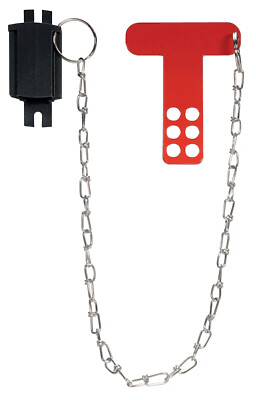
103051655 SZ201-1
- Suitable for mounting inside and outside of the hazardous area
- To prevent inadvertent closing, e.g. during maintenance
- For complex plant
- Prevents actuation of the switch
- Lockout tag with 6 circular holes
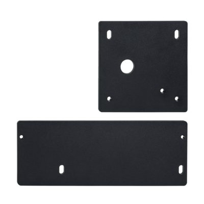
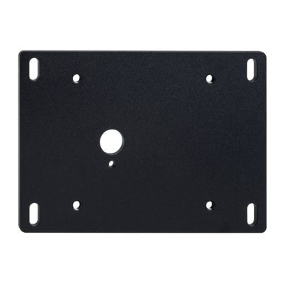
101214126 MOUNTING PLATES KPL. MP BDF 200
- Mounting plate for easy and quick assembly
- Metal, powder-coated
- suitable for left and right hinged doors
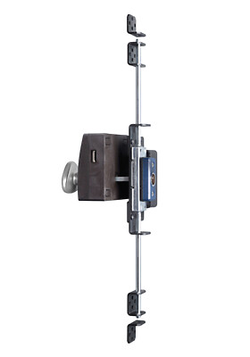
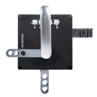
103004966 RF-AZM200/201-T
- Subsequent functional expansion of the solenoid interlock AZM200 / AZM201
- Emergency exit retrofit kit
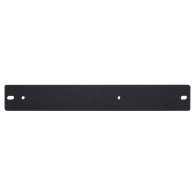
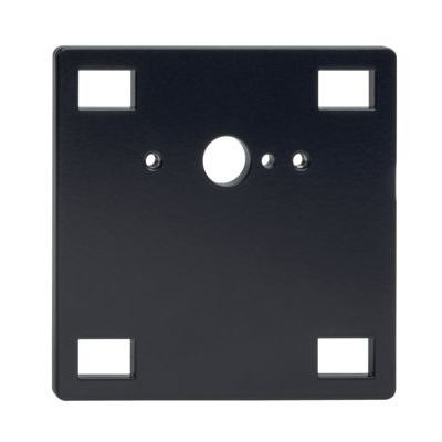
101188600 MOUNTING PLATE AZ/AZM200
- Mounting plate for easy and quick assembly
- Metal, powder-coated
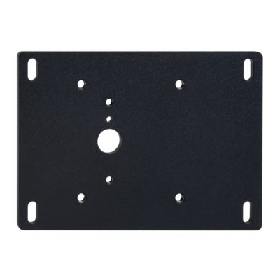
101194224 MOUNTING PLATE MP AZ/AZM200-P1
- Mounting plate for easy and quick assembly
- Metal, powder-coated
- suitable for left and right hinged doors
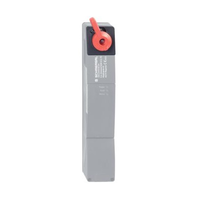
103003543 RF-AZM200/201-N
- Emergency release retrofit kit
- Subsequent functional expansion of the solenoid interlock AZM200 / AZM201
- optional lead sealing possible
101194218 MOUNTING PLATE MP AZ/AZM200-B30
- Mounting plate for easy and quick assembly
- Metal, powder-coated
- suitable for left and right hinged doors
101185694 MOUNTING PLATE MP AZ/AZM200-P20
- Mounting plate for easy and quick assembly
- Metal, powder-coated
- suitable for left and right hinged doors
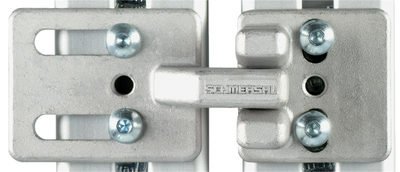
103001074 RF-AZ/AZM 200-B30-SZ
- enables the addition of an integrated lockout tag
- suitable for available B30 actuator systems
- Lockout tag with 3 circular holes
- For complex plant
- Prevents actuation of the switch
101166329 TFI-010
- Pre-positioning
- The actuator is independent from the centring device.
- Smooth insertion or retraction of the actuator
101166328 TFA-010
- Pre-positioning
- The actuator is independent from the centring device.
- Smooth insertion or retraction of the actuator

101196397 LOCKOUT TAG SZ 200-1
- Lockout tag with 6 circular holes
- Suitable for mounting inside and outside of the hazardous area
- To prevent inadvertent closing, e.g. during maintenance
- For complex plant
- Prevents actuation of the switch
| EU Declaration of Conformity |  |
| Original | K.A. Schmersal GmbH & Co. KG Möddinghofe 30 42279 Wuppertal Germany Internet: www.schmersal.com |
| Declaration: | We hereby certify that the hereafter described components both in their basic design and construction conform to the applicable European Directives. |
| Name of the component: | AZM201 |
| Type: | See ordering code |
| Description of the component: | Interlocking device with electromagnetic interlock for safety functions |
| Relevant Directives: | Machinery Directive | 2006/42/EC |
| RED-Directive | 2014/53/EU | |
| RoHS-Directive | 2011/65/EU |
| Applied standards: | EN 60947-5-3:2013 ISO 14119:2013 EN 300 330 V2.1.1:2017 EN ISO 13849-1:2015 EN 61508 parts 1-7:2010 |
| Notified body for Type Examination: | TÜV Rheinland Industrie Service GmbH Am Grauen Stein, 51105 Köln ID n°: 0035 |
| Type Examination Certificate: | 01/205/5608.01/22 |
| Person authorised for the compilation of the technical documentation: | Oliver Wacker Möddinghofe 30 42279 Wuppertal |
| Place and date of issue: | Wuppertal, August 10, 2022 |
 |
| Authorised signature Philip Schmersal Managing Director |
| UK Declaration of Conformity | |
| Company: | K.A. Schmersal GmbH & Co. KG Möddinghofe 30 42279 Wuppertal Germany Internet: www.schmersal.com |
| Declaration: | We hereby, under sole responsibility, certify that the hereafter described components both in their basic design and construction conform to the relevant statutory requirements, regulations and designated standards of the United Kingdom. |
| Name of the component: | AZM201 |
| Type: | See ordering code |
| Description of the component: | Interlocking device with electromagnetic interlock for safety functions |
| Relevant legislation: | Supply of Machinery (Safety) Regulations | 2008 |
| Radio Equipment Regulations | 2017 | |
| The Restriction of the Use of Certain Hazardous Substances in Electrical and Electronic Equipment Regulations | 2012 |
| Designated standards: | EN 60947-5-3:2013 ISO 14119:2013 EN 300 330 V2.1.1:2017 EN ISO 13849-1:2015 EN 61508 parts 1-7:2010 |
| Approved body for Type Examination: | TÜV Rheinland UK Ltd. 1011 Stratford Road Solihull, B90 4BN ID: 2571 |
| Type examination certificate: | 01/205U/5608.00/22 |
| UK-Importer / Person authorised for the compilation of the technical documentation: | Schmersal UK Ltd. Paul Kenney Unit 1, Sparrowhawk Close Enigma Business Park Malvern, Worcestershire, WR14 1GL |
| Place and date of issue: | Wuppertal, September 28, 2022 |
|
| Authorised signature Philip Schmersal Managing Director |
Schmersal, Inc., 115 E Stevens Ave, Suite 208, Valhalla, NY 10595
The details and data referred to have been carefully checked. Images may diverge from original. Further technical data can be found in the manual. Technical amendments and errors possible.
Generated on: 6/21/2025, 11:22 PM