BWU3635

BWU3635
- Can be used for CSS and RSS sensors, as well as for MZM 100, AZM 201, AZM 300, AZM40
- Safe active AS-i distributor
- Connections for profile cable AS-i & AUX
- With 2 fail-safe inputs for OSSDs and one digital output that is not fail-safe
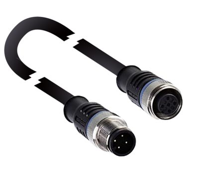
- M12, 8-pole connecting cable 1 m
- Protection class IP67
Ordering data
| Product type description |
BWU3635 |
| Article number (order number) |
103016678 |
| EAN (European Article Number) |
4030661508924 |
| eCl@ss number, version 12.0 |
27-24-26-04 |
| eCl@ss number, version 11.0 |
27-24-26-04 |
| eCl@ss number, version 9.0 |
27-24-26-04 |
| ETIM number, version 7.0 |
EC001599 |
| ETIM number, version 6.0 |
EC001599 |
General data
| Standards |
EN IEC 62026-2 EN IEC 62061 EN ISO 13849-1 |
| Housing material |
Plastic |
| Reaction time, maximum |
11 ms |
| Gross weight |
141 g |
General data - Features
| Safety functions |
Yes |
| Integral system diagnostics, status |
Yes |
| Safety classification |
| Vorschriften |
EN IEC 62061 |
| Performance Level, up to |
e |
| Category |
4 |
| PFH value |
5.18 x 10⁻⁹ /h |
| PFD value |
6.19 x 10⁻⁷ |
| Safety Integrity Level (SIL), suitable for applications in |
3 |
| Mission time |
20 Year(s) |
Mechanical data - Connection technique
| Length of cable |
1 m |
| Termination |
Cable connector M12, 8-pole, A-coded |
| Material of the cable |
PUR |
Mechanical data - Dimensions
| Width |
60 mm |
| Height |
45 mm |
| Depth |
19 mm |
Ambient conditions
| Degree of protection |
IP67 |
| Ambient temperature |
-20 ... +60 °C |
| Storage and transport temperature |
-30 ... +85 °C |
| Resistance to vibrations |
10 … 55 Hz, amplitude 0.5 mm |
| Restistance to shock |
15 g / 11 ms |
Electrical data - AS Interface
| Rated operating voltage |
21.6 ... 31.6 VDC |
| AS-i Current consumption, maximum |
60 mA |
Electrical data - AS-Interface specification
| AS-i Specification |
Safety-Slave |
| AS-i Version |
V 2.1 |
| AS-i Profile |
S-7.B.F.1 |
| AS-i Input, Channel 1 |
Data bits DI 0 / DI 1 = dynamic code transmission |
| AS-i Input, Channel 2 |
Data bits DI 2 / DI 3 = dynamic code transmission |
| AS-i Outputs, DO 0 |
Digital output, Solenoid control |
| AS-i Outputs, DO 1 … DO 3 |
No Function |
| AS-i Parameter bits, P0 |
Control system watchdog |
| AS-i Parameter bits, P1 |
Diagnostics signal safety switchgear (inverted) |
| AS-i Parameter bits, P2 ... P3 |
No function |
| Note (AS-i Parameter bits) |
Set the parameter outputs to "1111" (0xF) |
| AS-i Input module address |
0 |
| Note (AS-i Input module address) |
Preset to address 0, can be changed through AS-interface bus master or hand-held programming device |
Electrical data - Auxiliary voltage
| Operating voltage |
24 VDC -15 % / +10 % (stabilised PELV power supply) |
| Rated operating voltage |
24 VDC |
Status indication
| Note (LED switching conditions display) |
(1) green/red LED (AS-i duo LED): Supply voltage / communication error / slave address = 0 / periphery error detected (2) LED green: AUX-Power available (3) LED yellow: S1 = Status safety input 1 (4) LED yellow: S2 = Status safety input 2 (5) LED yellow: I1 = Status input I1 (6) LED yellow: o1 = Status output o1 |
Note
| Note voltage AUX DC |
stabilised PELV power supply |
Language filter
Datasheet
Operating instructions and Declaration of conformity
Mounting and wiring instructions
Datasheet (provisional PDF)
SISTEMA-VDMA library
Download the latest version of Adobe Reader
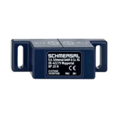
Product picture (catalogue individual photo)
Schmersal, Inc., 115 E Stevens Ave, Suite 208, Valhalla, NY 10595
The details and data referred to have been carefully checked. Images may diverge from original. Further technical data can be found in the manual. Technical amendments and errors possible.
Generated on: 8/11/2025, 6:04 AM
Recently viewed