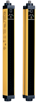
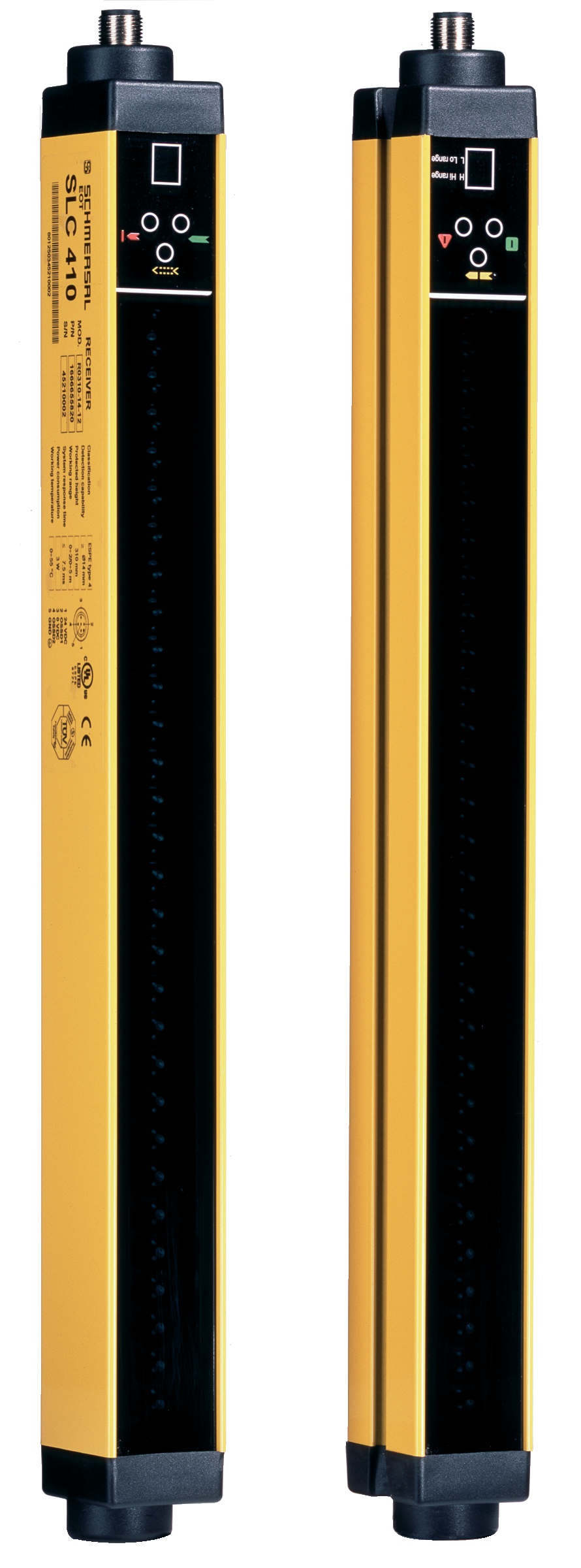
SLG 412-E/R0500-02-12
SLG 412-E/R0500-02-12
Downloads
- NOTICE: Not available! (Replacement: SLG 422)
- Integrated start/restart interlock
- Integrated contactor control
- Status display
- Optical sychronisation
- Fail-safe transistor outputs
- Control Category 4
Ordering data
| Note (Delivery capacity) |
Not available! |
| Product type description |
SLG 412-E/R0500-02-12 |
| Article number (order number) |
101186045 |
| eCl@ss number, version 12.0 |
27-27-27-03 |
| eCl@ss number, version 11.0 |
27-27-27-03 |
| eCl@ss number, version 9.0 |
27-27-27-03 |
| ETIM number, version 7.0 |
EC001832 |
| ETIM number, version 6.0 |
EC001832 |
General data
| Standards |
EN IEC 61496-2 EN IEC 61496-1 |
| Design of multi-ray photoelectric barrier |
Emitter and receiver, separated |
| Housing material |
Aluminium |
| Beam distance |
500 mm |
| Reaction time, maximum |
7 ms |
| Gross weight |
5,000 g |
General data - Features
| Preliminary failure signal |
Yes |
| Restart interlock (manual reset) |
Yes |
| Beam coding available |
Yes |
| Integral system diagnostics, status |
Yes |
| Integral system diagnostics |
Yes |
| Number of semi-conductor outputs with signaling function |
1 |
| Number of fail-safe digital outputs |
2 |
| Number of beams |
2 |
| Safety classification |
| Safety type in accordance with IEC 61496-1 |
4 |
Mechanical data
| Height of the protection field |
510 mm |
| Range, protection field, minimum |
0 m |
| Range, protection field, maximum |
16 m |
| Wave length of the laserdiode |
950 nm |
Mechanical data - Connection technique
| Termination |
Connector |
| Terminal connector, Recipient |
Connector plug M23, 19-pole |
| Terminal, Connector, Transmitter |
Connector plug M12, 5-pole |
Mechanical data - Dimensions
| Length of sensor |
50 mm |
| Width of sensor |
60 mm |
| Height of sensor |
736 mm |
Ambient conditions
| Degree of protection |
IP65 |
| Ambient temperature |
+0 ... +55 °C |
| Storage and transport temperature |
-20 ... +70 °C |
| Protection class |
III |
Electrical data
| Switching voltage OSSD, HIGH signal |
24 V |
| Electrical power consumption of the receiver |
6 W |
| Electrical power consumption of the transmitter |
3 W |
| Length of cable, maximum |
100 m |
Electrical data - Safety digital outputs
| Output current, (fail-safe output), maximum |
0.5 A |
| Design of control elements |
p-type |
Scope of delivery
| Scope of delivery |
Emitter + receiver, mounting angle, T-slot nuts |
Accessory
| Recommended safety switchgear |
SCR 402R-301 |
Note
| Note (General) |
Im In case of failure (interruption of the 0 V supply) the maximum leakage current is 0.3 mA. |
Language filter
Datasheet
Mounting and wiring instructions
Download the latest version of Adobe Reader
Product picture (catalogue individual photo)
Schmersal, Inc., 115 E Stevens Ave, Suite 208, Valhalla, NY 10595
The details and data referred to have been carefully checked. Images may diverge from original. Further technical data can be found in the manual. Technical amendments and errors possible.
Generated on: 8/3/2025, 4:30 AM
.png?id=e5ef4d56dad486103335c34b5b46f1ce)


