RSS260-123456 Test
RSS260-123456 Test
- Codifica universale con tecnologia RFID
- 1 x Connettore maschio incorporato M8
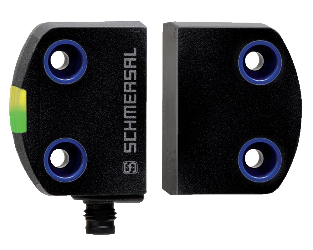
- Possibilità di azionamento frontale e laterale
- Custodia in plastica
- Montaggio semplice senza angolo aggiuntivo
- Protezione da manomissione con la tecnologia RFID in base alle necessità
Dati per l'ordine
| Nota (possibilità di fornitura) |
Non più disponibile! |
| Codice |
RSS260-123456 Test |
| Codice articolo (codice d'ordine) |
999999988 |
| EAN (European Article Number) |
4030661436418 |
| eCl@ss number, version 12.0 |
27-27-46-01 |
| eCl@ss number, version 11.0 |
27-27-24-03 |
| Numero eCl@ss, versione 9.0 |
27-27-24-03 |
| ETIM number, version 7.0 |
EC001829 |
| ETIM number, version 6.0 |
EC001829 |
Dati generali
| Prescrizioni |
EN IEC 60947-5-3 |
| informazioni generali |
Codifica universale |
| Livello di codifica secondo EN ISO 14119 |
ridotta |
| principio d'azione |
RFID |
| forma costruttiva dell'alloggiamento |
parallelepipedo |
| condizioni di montaggio (meccanico) |
non allineato |
| Topologia del sensore |
Sensore per azionamento in serie |
| Materiale della custodia |
Plastica, termoplastica, autoestinguente |
| Area attiva |
materiale sintetico, termoplastica |
| Tempo di reazione, massimo |
100 ms |
| Tempo di rischio, massimo |
200 ms |
| Peso lordo |
47 g |
Dati generali - Caratteristiche
| Uscita di diagnosi |
Sì |
| Riconoscimento cortocircuiti |
Sì |
| Riconoscimento di corto circuito |
Sì |
| Funzioni di sicurezza |
Sì |
| Possibilità di collegamento in cascata |
Sì |
| Display integrato, stato |
Sì |
| Numero di LED |
3 |
| Numero di uscite semiconduttore con funzione di segnalazione |
1 |
| Numero di uscite digitali sicure |
2 |
Osservazioni per la sicurezza
| Norma, Prescrizioni |
EN ISO 13849-1 EN IEC 60947-5-3 EN IEC 62061 EN IEC 61508 |
| Performance Level, fino a |
e |
| Categoria secondo EN ISO 13849 |
4 |
| Valore PFH |
6,80 x 10⁻¹⁰ /h |
Safety Integrity Level (SIL), idoneo per applicazioni in |
3 |
| Durata di utilizzo |
20 Anno(i) |
Dati meccanici
| Piano di azionamento |
lateralmente lato frontale |
| Area attiva |
lateralmente davanti |
| Montaggio |
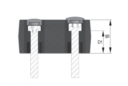
Per il montaggio dei sensori sono sufficienti viti comuni lunghe 20 mm. In caso di utilizzo delle piastre di montaggio si raccomanda l'uso di viti lunghe 25 mm. |
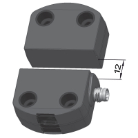
Mechanical data - Switching distances
| intervallo di commutazione |
davanti 12 mm lateralmente 9 mm |
| Distanza di commutazione sicura "ON" Sao, frontale |
10 mm |
| Distanza di commutazione sicura "OFF" Sar, frontale |
18 mm |
| Distanza di commutazione sicura "ON" Sao, laterale |
6 mm |
| Distanza di commutazione sicura "OFF" Sar, laterale |
15 mm |
| Note (switching distance) |
All switching distances in accordance EN IEC 60947-5-3 |
| Isteresi (Distanza di commutazion), massimo |
2 mm |
| Precisione di ripetizione R |
0,5 mm |
| Nota (Precisione di ripetizione R) |
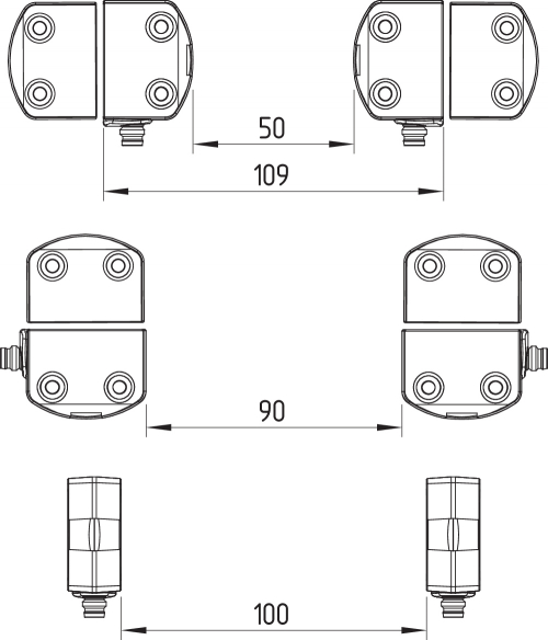
Spostamento assiale laterale: La superficie laterale lunga permette un disallineamento in altezza massimo (x) tra sensore ed azionatore di 8 mm (ad es. tolleranza di montaggio o per abbassamento della porta di sicurezza). Lo scostamento trasversale (Y) è pari a max. ± 18 mm (vedi figura: Funzionamento).Distanza minima per azionamento laterale 100 mm |
Dati meccanici - Tecnologia di collegamento
| Note (length of the sensor chain) |
Cable length and cross-section change the voltage drop dependiing on the output current |
| Connettore di collegamento |
connettore ad innesto M8 |
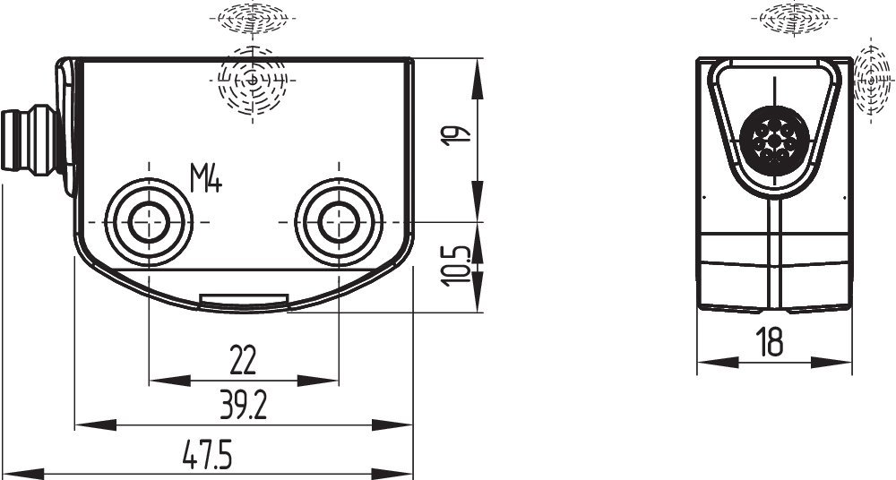
Dati meccanici - Dimensioni
| lunghezza del sensore |
29,5 mm |
| larghezza del sensore |
39,2 mm |
| altezza del sensore |
18 mm |
Condizioni ambientali
| Grado di protezione |
IP65 IP67 |
| Temperatura ambiente |
-25 ... +65 °C |
| Temperatura di stoccaggio e trasporto |
-25 ... +85 °C |
| Resistenza alle vibrazioni secondo EN 60068-2-6 |
10…55 Hz, ampiezza 1 mm |
| resistenza a urti |
30 g / 11 ms |
Condizioni ambientali - Valori di isolamento
| Tensione d'isolamento nominale |
32 VDC |
| Resistenza alla tensione impulsiva nominale |
0,8 kV |
| Categoria di sovratensione |
III |
| Grado di inquinamento secondo VDE 0100 |
3 |
Dati elettrici
| Operating voltage |
24 VDC -15 % / +10 % |
| No-load supply current I0, typical |
100 mA |
| Rated operating voltage |
24 VDC |
| Corrente di funzionamento |
600 mA |
| Corrente nominale di cortocircuito condizionata secondo EN 60947-5-1 |
100 A |
| Ritardo di disponibilità, massimo |
2.000 ms |
| Frequenza di commutaz, circa |
1 Hz |
| Utilisation category DC-12 |
24 VDC / 0,05 A |
Dati elettrici - Uscite digitali sicure
| Versione |
con commutazione p |
| Caduta di tensione Ud, massimo |
1 V |
| corrente residua |
0,5 mA |
| Tensione, Categoria d'utilizzo DC-12 |
24 VDC |
| Corrente, categoria d'utilizzo DC-12 |
0,25 A |
| Tensione, Categoria d'utilizzo DC-13 |
24 VDC |
| Corrente, categoria d'utilizzo DC-13 |
0,25 A |
Dati elettrici - Uscita di diagnosi
| Versione |
commutazione p |
| Caduta di tensione Ud, massimo |
2 V |
| Tensione, Categoria d'utilizzo DC-12 |
24 VDC |
| Corrente, categoria d'utilizzo DC-12 |
0,05 A |
| Tensione, Categoria d'utilizzo DC-13 |
24 VDC |
| Corrente, categoria d'utilizzo DC-13 |
0,05 A |
Dati elettrici - Compatibilità elettromagnetica (EMC)
| Interferenza emessa |
IEC 61000-6-4 |
| Resistenza alle interferenze |
IEC 60947-3 |
Segnalazione di stato
| Osservazioni (Indicatori di stato a LED) |
LED giallo: Stato operativo LED verde: Tensione di alimentazione LED rosso: Errore |
Pin dei contatti
| Pin 1 |
A1 Ue: Bianco |
| Pin 2 |
X1 Ingresso di sicurezza 1: Marrone |
| Pin 3 |
A2 GND: Verde |
| Pin 4 |
Y1 Uscita di sicurezza 1: Giallo |
| Pin 5 |
OUT Uscita di diagnosi OUT grigio |
| Pin 6 |
X2 Ingresso di sicurezza 2: Rosa |
| Pin 7 |
Y2 Uscita di sicurezza 2: Blu |
| Pin 8 |
IN senza funzione: Rosso |
Accessori
| Raccomandazione, (Azionatore) |
RST16-1 RST-U-2 RST260-1 |
| Raccomandazione dispositivo di sicurezza |
PROTECT PSC1 SRB-E-301ST SRB-E-201LC |
Filtro lingua
Scheda Tecnica
Manuale d'istruzioni e dichiarazione UE di conformità
Brochure
Libreria SISTEMA-VDMA
Download dell'ultima versione di Adobe Reader
Immagine del prodotto (foto singola per catalogo)
Video ID: RSS-260-01
Basic function (Vimeo)

Video ID: RSS-260-02
Variable mounting options (Vimeo)
Video ID: RSS-260-03
Single device connection (Vimeo)
Video ID: RSS-260-04
Series connection with serial diagnostics (Vimeo)
Video ID: RSS-260-05
Cross-fault with controlled shut-down process (Vimeo)
Video ID: RSS-260-06
Tolerance to misalignment (Vimeo)
Video ID: RSS-260-07
Warning when actuator is in limit range (Vimeo)
Video ID: RSS-260-11
RST-16-1 actuator on flat contour safety guards (Vimeo)
Video ID: RSS-260-12
RST-U-2 actuator for confined spaces (Vimeo)
Video ID: RSS260-13
Produktinformation RSS260 (Vimeo)
Indice dei contenuti
- 1 Informazioni sul presente documento
- 1.1 Funzione
- 1.2 A chi è rivolto il Manuale d'istruzioni: personale specializzato autorizzato
- 1.3 Simbologia utilizzata
- 1.4 Uso conforme
- 1.5 Note generali di sicurezza
- 2 Descrizione del prodotto
- 2.1 Codice prodotto
- 2.2 Versioni speciali
- 2.3 Destinazione d'uso
- 2.4 Avvertenza in caso di uso non corretto
- 2.5 Liberatoria
- 3 Dati tecnici
- 4 Montaggio
- 4.1 Istruzioni di montaggio
- 4.2 Direzioni di azionamento
- 4.3 Dimensioni
- 4.4 Accessori
- 4.5 intervallo di commutazione
- 4.6 Regolazione
- 5 Collegamento elettrico
- 5.1 Note generali sul collegamento elettrico
- 5.2 Diagnosi seriale -SD
- 5.3 Per esempi di collegamenti in serie
- 5.4 Assegnazione dei collegamenti e connettori accessori
- 6 Codifica dell'azionatore
- 7 Principio d'azione e Funzione di diagnosi
- 7.1 Uscite di sicurezza
- 7.2 LED di diagnosi
- 7.3 Principio di funzionamento dell'uscita di diagnosi convenzionale
- 7.4 Sensori di sicurezza con funzione di diagnosi seriale
- 8 Messa in servizio e manutenzione
- 9 Smontaggio e smaltimento
- 9.1 Smontaggio
- 9.2 Smaltimento
1 Informazioni sul presente documento
1.1 Funzione
Il presente documento fornisce le informazioni richieste per il montaggio, la messa in servizio, il funzionamento sicuro e lo smontaggio del dispositivo di sicurezza. Conservare il manuale d'istruzioni allegato al dispositivo in condizioni leggibili e in un luogo facilmente accessibile.
1.2 A chi è rivolto il Manuale d'istruzioni: personale specializzato autorizzato
Le operazioni descritte nel Manuale d'istruzioni dovranno essere eseguite solo da personale specializzato qualificato e autorizzato dall'operatore dell'impianto.
Installare e utilizzare il dispositivo solo dopo avere letto e compreso il presente manuale d'istruzioni ed essendo a conoscenza delle disposizioni vigenti in materia di sicurezza sul lavoro e prevenzione degli infortuni.
La selezione e l'installazione dei dispositivi, così come i relativi collegamenti di controllo, richiedono una conoscenza approfondita delle normative di settore e dei requisiti di legge da parte del costruttore di macchine.
Il produttore non si assume alcuna responsabilità per quanto dichiarato. Si riserva il diritto di apportare modifiche tecniche migliorative.
1.3 Simbologia utilizzata
- Informazione, Suggerimento, Nota: Questo simbolo segnala utili informazioni aggiuntive.
- Attenzione: La mancata osservanza di questa nota di avvertenza può causare guasti o malfunzionamenti.
Avvertenza: La mancata osservanza di questa nota di avvertenza può causare danni personali e/o danni materiali alla macchina.
1.4 Uso conforme
La gamma di prodotti Schmersal non è destinata ai consumatori privati.
I prodotti qui descritti sono stati sviluppati come componenti d'impianto o di una macchina per lo svolgimento di funzioni di sicurezza. È responsabilità del produttore dell'impianto o della macchina garantire il corretto funzionamento generale.
Il dispositivo di sicurezza può essere installato solo conformemente alle seguenti applicazioni o per quelle autorizzate dal produttore. Per informazioni dettagliate sul campo d'impiego, vedere il capitolo “Descrizione del prodotto”.
1.5 Note generali di sicurezza
Osservare le note di sicurezza riportate nel manuale d'istruzioni, nonché le disposizioni nazionali relative ad installazione, sicurezza e prevenzione degli infortuni.
- Per ulteriori informazioni tecniche si rimanda ai cataloghi Schmersal o al catalogo online disponibile in Internet all'indirizzo products.schmersal.com.
2 Descrizione del prodotto
2.1 Codice prodotto
| Codice: RSS260-(1)-(2)-(3)-(4)-(5) |
| (1) | |
| senza | Codifica standard |
| I1 | Codifica individuale |
| I2 | Codifica individuale, Teach-in ripetibile |
| (2) | |
| D | Con uscita di diagnosi |
| SD | con funzione di diagnosi seriale |
| (3) | |
| senza | Versione standard senza sorveglianza circuito di retroazione EDM (External Device Monitoring) |
| F0 | EDM con reset automatico |
| F1 | EDM con reset manuale |
| (4) | |
| senza | Senza arresto d'emergenza |
| Q | Conferma errori ingressi tramite arresto d'emergenza |
| (5) | |
| senza | Cavo di collegamento: (lunghezza in metri) |
| ST | Connettore maschio incorporato M8, 8 poli |
| LSTM12-8-0,25M | Cavo di collegamento da 0,25 m con connettore M12, 8 poli |
| LSTM8-8-0,1M | Cavo di collegamento da 0,1 m con connettore M8, 8 poli |
| LSTM12-5-0,25M | Cavo di collegamento da 0,25 m con connettore M12, 5 poli |
2.2 Versioni speciali
Per le versioni speciali con codice diverso da quanto elencato alla sezione Codice prodotto, le indicazioni riportate in precedenza e nel seguito si applicano solo nella misura in cui tali versioni sono conformi all'esecuzione di serie.
2.3 Destinazione d'uso
Il sensore di sicurezza elettronico senza contatto è idoneo per l'impiego in circuiti di sicurezza e serve per il controllo di posizione di dispositivi di protezione mobili. Il sensore di sicurezza controlla la posizione di dispositivi di protezione ruotabili, traslabili lateralmente o anche removibili per mezzo dell'azionatore elettronico codificato.
La funzione di sicurezza consiste nella disattivazione sicura delle uscite di sicurezza all'apertura del dispositivo di protezione e nel mantenimento sicuro di tale disattivazione con dispositivo di protezione aperto.
- I dispositivi di sicurezza sono classificati secondo EN ISO 14119 come dispositivi di blocco di tipo 4. Le versioni con codifica personalizzata sono classificati "a codifica alta".
Con l'opzione F0/F1 il sensore esegue le funzioni proprie di un modulo di sicurezza a relè. Ad entrambe le uscite di sicurezza è possibile collegare due contattori ausiliari1) o relè1), ciascuno con contatti ad azione obbligata secondo EN 60947-5-1 o EN 50205), la cui funzione di sicurezza viene controllata dal sensore tramite un circuito di retroazione (External Device Monitoring). Il circuito di retroazione include il cablaggio per il collegamento in serie dei contatti NC dei contattori ausiliari o dei relè. Nella versione F0 è inoltre possibile collegare nel circuito di retroazione un "pulsante di abilitazione" (senza funzione di sicurezza). Nella versione F1 è richiesto un cosiddetto "pulsante di reset", con sorveglianza per fronte di discesa. Questa funzione è conforme alla "funzione di reset manuale" secondo EN ISO 13849-1.
L'opzione Q sorveglia la disconnessione simultanea degli ingressi del sensore. In caso di collegamento in serie del sensore, questo permette l'integrazione di elementi di commutazione di arresto d'emergenza per applicazioni fino a PL e. I contatti di arresto d'emergenza sono alimentati dai segnali di uscita con sorveglianza anticortocircuito di un dispositivo di sicurezza elettronico a monte. Alla fine della catena, un sensore con opzione Q per il collegamento di una funzione di conferma controlla la catena per la disconnessione sincrona di entrambi i canali. In caso di disconnessione non conforme, il problema deve essere eliminato. Le uscite di sicurezza possono essere riattivate solo dopo la conferma dell'errore.
L'uscita di diagnosi del sensore di sicurezza può essere alternativamente selezionata come uscita convenzionale o come "uscita seriale" con un canale di ingresso e uscita.
È possibile realizzare un azionamento in serie. In caso di collegamento in serie, il tempo di rischio rimane invariato e il tempo di reazione aumenta in misura pari alla somma dei tempi di reazione degli ingressi, riportati nei dati tecnici, per ciascun dispositivo aggiuntivo. Il numero dei dispositivi è limitato solo dalle perdite del cavo e dal fusibile di linea esterno, in base ai dati tecnici e alle perdite del cavo ammissibili. Nel caso di varianti con funzione di diagnosi seriale è possibile collegare in serie fino a 31 dispositivi.
- La valutazione e la progettazione della catena di sicurezza dovranno essere eseguite dall'utente nel rispetto delle norme e prescrizioni applicabili e in base al livello di sicurezza richiesto. Se alla stessa funzione di sicurezza sono collegati più sensori di sicurezza, è necessario sommare i valori PFH dei singoli componenti.
- Il progetto globale del controllo nel quale saranno integrati i componenti di sicurezza dovrà essere convalidato secondo le norme rilevanti.
2.4 Avvertenza in caso di uso non corretto
- L'eventuale utilizzo non corretto o non conforme o interventi non autorizzati possono causare pericoli per le persone o danni a componenti della macchina o dell'impianto in seguito all'impiego del dispositivo di sicurezza. Non sono noti altri rischi in caso di osservanza delle note sulla sicurezza e delle istruzioni di montaggio, messa in servizio, funzionamento e manutenzione.
2.5 Liberatoria
Il produttore non si assume alcuna responsabilità per danni e malfunzionamenti operativi dovuti ad errori di montaggio o alla mancata osservanza del presente manuale d'istruzioni. È esclusa inoltre ogni ulteriore responsabilità del produttore per danni risultanti dall'utilizzo di parti di ricambio o accessori non autorizzati dal produttore.
Per motivi di sicurezza non è permesso effettuare riparazioni, conversioni e modifiche arbitrarie e il produttore non si assume alcuna responsabilità per eventuali danni risultanti da tali operazioni.
3 Dati tecnici
| Prescrizioni | EN ISO 13849-1, EN ISO 14119, EN IEC 60947-5-3, EN IEC 61508 |
| Livello di codifica secondo EN ISO 14119 | ridotta |
| Livello di codifica secondo EN ISO 14119 | alto |
| principio d'azione | RFID |
| Banda di frequenza RFID | 125 kHz |
| Potenza di trasmissione RFID, massimo | -6 dB/m |
| Ritardo di disponibilità, massimo | 5000 ms |
| Tempo di rischio, massimo | 200 ms |
| Tempo di reazione delle uscite di sicurezza in caso di disattivazione tramite azionatore, massimo | 100 ms |
| Tempo di reazione delle uscite di sicurezza in caso di disattivazione tramite ingressi di sicurezza, massimo | 1.5 ms |
| Grado di protezione | IP66, IP67, IP69 |
| Prescrizioni | EN ISO 13849-1, EN IEC 61508 |
| Performance Level, fino a | e |
| Categoria | 4 |
| Valore PFH | 0.00000000052 /h |
| Valore PFD | 0.000045 |
| Safety Integrity Level (SIL), idoneo per applicazioni in | 3 |
| Durata di utilizzo | 20 anni |
| Performance Level, fino a | d |
| Categoria di comando | 2 |
| Valore PFH | 2,00 x 10⁻⁹ /h |
| Valore PFD | 1,80 x 10⁻⁴ |
| Safety Integrity Level (SIL), idoneo per applicazioni in | 2 |
| Durata di utilizzo | 20 anni |
| Durata meccanica, minimo | 1000000 manovre |
| Osservazioni (durata meccanica) | Se usato come fermaporta: ≥ 50.000 cicli di operazioni (massa della porta ≤ 5 kg e velocità di attuazione ≤ 0,5 m/s) |
| Spostamento angolare tra ritenuta e azionatore, massimo | 2 ° |
| Forza di mantenimento in chiusura Fmax, massima | 1500 N |
| Forza di mantenimento FZh in chiusura secondo EN ISO 14119 | 1150 N |
| Forza di ritenuta (Posizione 1 / Posizione 2) | 25 N / 50 N |
| Versione delle viti di fissaggio | 2x M6 |
| Coppia di serraggio delle viti di fissaggio | 6 ... 7 Nm |
| Distanza di commutazione, tipico | 2 mm |
| Distanza di commutazione sicura "ON" Sao | 1 mm |
| Distanza di commutazione sicura "OFF" Sar | 20 mm |
| tipo di collegamento | Connettore M12, 8 poli, codifica A |
| Lunghezza della catena di sensori, massimo | 200 m |
| Osservazioni (Lunghezza della catena di sensori) | La lunghezza del cavo e la relativa sezione influenzano la caduta di tensione in funzione della corrente d'uscita |
| Osservazioni (Azionamento in serie) | Numero di dispositivi illimitato, osservare la protezione cavo esterna, max. 31 dispositivi con diagnosi seriale |
| Tensione d'esercizio | 24 VDC -15% / +10% (alimentatore PELV stabilizzato) |
| Corrente a vuoto I0, tipica | 100 mA |
| Assorbimento di corrente con magnete ON, valore medio | 200 mA |
| Assorbimento di corrente con magnete ON, valore di picco | 350 mA / 200 ms |
| Corrente di cortocircuito nominale richiesta | 100 A |
| Protezione esterna cavo e dispositivo | 2 A gG |
| Frequenza di commutaz, massimo | 0.5 Hz |
| Denominazione, Comando magnete | IN |
| Soglie di commutazione | -3 V … 5 V (Low) 15 V … 30 V (High) |
| Assorbimento di corrente a 24 V | 10 mA |
| Durata dell'impulso di prova, massimo | 5 ms |
| Intervallo dell'impulso di prova, minimo | 40 ms |
| Denominazione, Ingressi di sicurezza | X1 e X2 |
| Soglie di commutazione | −3 V … 5 V (Low) 15 V … 30 V (High) |
| Assorbimento di corrente a 24 V | 5 mA |
| Durata dell'impulso di prova, massimo | 1 ms |
| Intervallo dell'impulso di prova, minimo | 100 ms |
| Denominazione, Uscite di sicurezza | Y1 e Y2 |
| Esecuzione degli elementi di commutazione | resistente a cortocircuito, con commutazione p |
| Caduta di tensione Ud, massimo | 2 V |
| Corrente residua Ir, massimo | 0.5 mA |
| Categoria d'utilizzo DC-12 | 24 VDC / 0,25 A |
| Categoria d'utilizzo DC-13 | 24 VDC / 0,25 A |
| Durata dell'impulso di prova, massimo | 0.5 ms |
| Intervallo dell'impulso di prova, tipicamente | 1000 ms |
| Designazione, Uscite diagnostiche | OUT |
| Esecuzione degli elementi di commutazione | resistente a cortocircuito, con commutazione p |
| Caduta di tensione Ud, massimo | 2 V |
| Categoria d'utilizzo DC-13 | 24 VDC / 0,05 A |
| Denominazione, Diagnosi seriale -SD | OUT |
| Esecuzione degli elementi di commutazione | resistente a cortocircuito, con commutazione p |
| corrente di servizio | 150 mA |
| Capacità cavo | 50 nF |
| Categoria d'utilizzo DC-12, uscita di diagnosi | 24 VDC / 0,05 A |
Dati generali
| Prescrizioni |
EN IEC 60947-5-3 |
| informazioni generali |
Codifica universale |
| Livello di codifica secondo EN ISO 14119 |
ridotta |
| principio d'azione |
RFID |
| forma costruttiva dell'alloggiamento |
parallelepipedo |
| condizioni di montaggio (meccanico) |
non allineato |
| Topologia del sensore |
Sensore per azionamento in serie |
| Materiale della custodia |
Plastica, termoplastica, autoestinguente |
| Area attiva |
materiale sintetico, termoplastica |
| Tempo di reazione, massimo |
100 ms |
| Tempo di rischio, massimo |
200 ms |
| Peso lordo |
47 g |
Dati generali - Caratteristiche
| Uscita di diagnosi |
Sì |
| Riconoscimento cortocircuiti |
Sì |
| Riconoscimento di corto circuito |
Sì |
| Funzioni di sicurezza |
Sì |
| Possibilità di collegamento in cascata |
Sì |
| Display integrato, stato |
Sì |
| Numero di LED |
3 |
| Numero di uscite semiconduttore con funzione di segnalazione |
1 |
| Numero di uscite digitali sicure |
2 |
Osservazioni per la sicurezza
| Norma, Prescrizioni |
EN ISO 13849-1 EN IEC 60947-5-3 EN IEC 62061 EN IEC 61508 |
| Performance Level, fino a |
e |
| Categoria secondo EN ISO 13849 |
4 |
| Valore PFH |
6,80 x 10⁻¹⁰ /h |
Safety Integrity Level (SIL), idoneo per applicazioni in |
3 |
| Durata di utilizzo |
20 Anno(i) |
Dati meccanici
| Piano di azionamento |
lateralmente lato frontale |
| Area attiva |
lateralmente davanti |
| Montaggio |
Per il montaggio dei sensori sono sufficienti viti comuni lunghe 20 mm. In caso di utilizzo delle piastre di montaggio si raccomanda l'uso di viti lunghe 25 mm. |
Mechanical data - Switching distances
| intervallo di commutazione |
davanti 12 mm lateralmente 9 mm |
| Distanza di commutazione sicura "ON" Sao, frontale |
10 mm |
| Distanza di commutazione sicura "OFF" Sar, frontale |
18 mm |
| Distanza di commutazione sicura "ON" Sao, laterale |
6 mm |
| Distanza di commutazione sicura "OFF" Sar, laterale |
15 mm |
| Note (switching distance) |
All switching distances in accordance EN IEC 60947-5-3 |
| Isteresi (Distanza di commutazion), massimo |
2 mm |
| Precisione di ripetizione R |
0,5 mm |
| Nota (Precisione di ripetizione R) |
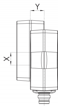
Spostamento assiale laterale: La superficie laterale lunga permette un disallineamento in altezza massimo (x) tra sensore ed azionatore di 8 mm (ad es. tolleranza di montaggio o per abbassamento della porta di sicurezza). Lo scostamento trasversale (Y) è pari a max. ± 18 mm (vedi figura: Funzionamento).Distanza minima per azionamento laterale 100 mm |
Dati meccanici - Tecnologia di collegamento
| Note (length of the sensor chain) |
Cable length and cross-section change the voltage drop dependiing on the output current |
| Connettore di collegamento |
connettore ad innesto M8 |
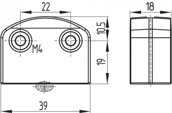
Dati meccanici - Dimensioni
| lunghezza del sensore |
29,5 mm |
| larghezza del sensore |
39,2 mm |
| altezza del sensore |
18 mm |
Condizioni ambientali
| Grado di protezione |
IP65 IP67 |
| Temperatura ambiente |
-25 ... +65 °C |
| Temperatura di stoccaggio e trasporto |
-25 ... +85 °C |
| Resistenza alle vibrazioni secondo EN 60068-2-6 |
10…55 Hz, ampiezza 1 mm |
| resistenza a urti |
30 g / 11 ms |
Condizioni ambientali - Valori di isolamento
| Tensione d'isolamento nominale |
32 VDC |
| Resistenza alla tensione impulsiva nominale |
0,8 kV |
| Categoria di sovratensione |
III |
| Grado di inquinamento secondo VDE 0100 |
3 |
Dati elettrici
| Operating voltage |
24 VDC -15 % / +10 % |
| No-load supply current I0, typical |
100 mA |
| Rated operating voltage |
24 VDC |
| Corrente di funzionamento |
600 mA |
| Corrente nominale di cortocircuito condizionata secondo EN 60947-5-1 |
100 A |
| Ritardo di disponibilità, massimo |
2.000 ms |
| Frequenza di commutaz, circa |
1 Hz |
| Utilisation category DC-12 |
24 VDC / 0,05 A |
Dati elettrici - Uscite digitali sicure
| Versione |
con commutazione p |
| Caduta di tensione Ud, massimo |
1 V |
| corrente residua |
0,5 mA |
| Tensione, Categoria d'utilizzo DC-12 |
24 VDC |
| Corrente, categoria d'utilizzo DC-12 |
0,25 A |
| Tensione, Categoria d'utilizzo DC-13 |
24 VDC |
| Corrente, categoria d'utilizzo DC-13 |
0,25 A |
Dati elettrici - Uscita di diagnosi
| Versione |
commutazione p |
| Caduta di tensione Ud, massimo |
2 V |
| Tensione, Categoria d'utilizzo DC-12 |
24 VDC |
| Corrente, categoria d'utilizzo DC-12 |
0,05 A |
| Tensione, Categoria d'utilizzo DC-13 |
24 VDC |
| Corrente, categoria d'utilizzo DC-13 |
0,05 A |
Dati elettrici - Compatibilità elettromagnetica (EMC)
| Interferenza emessa |
IEC 61000-6-4 |
| Resistenza alle interferenze |
IEC 60947-3 |
Segnalazione di stato
| Osservazioni (Indicatori di stato a LED) |
LED giallo: Stato operativo LED verde: Tensione di alimentazione LED rosso: Errore |
Pin dei contatti
| Pin 1 |
A1 Ue: Bianco |
| Pin 2 |
X1 Ingresso di sicurezza 1: Marrone |
| Pin 3 |
A2 GND: Verde |
| Pin 4 |
Y1 Uscita di sicurezza 1: Giallo |
| Pin 5 |
OUT Uscita di diagnosi OUT grigio |
| Pin 6 |
X2 Ingresso di sicurezza 2: Rosa |
| Pin 7 |
Y2 Uscita di sicurezza 2: Blu |
| Pin 8 |
IN senza funzione: Rosso |
UL - Osservazioni
- Da utilizzare nelle applicazioni NFPA 79. Gli adattatori che consentono il cablaggio sul campo sono disponibili presso il produttore. Attenersi alle informazioni del produttore. Da utilizzare in ambienti con grado di inquinamento 2.
FCC/IC - Osservazioni
Questo dispositivo è conforme alle disposizioni della Parte 15 delle normative FCC (Federal Communications Commission) USA e include trasmettitori/ricevitori che soddisfano i requisiti di esenzione dalla licenza secondo gli standard RSS di ISED (Innovation, Science and Economic Development) Canada.
Il funzionamento è soggetto alle due condizioni seguenti:
(1) il dispositivo non deve causare interferenze pericolose, e
(2) il dispositivo deve tollerare le interferenze ricevute, incluse le interferenze che possano causare un funzionamento indesiderato.
Il dispositivo è conforme ai limiti di esposizione per stimolazione nervosa (ISED SPR-002) per funzionamento con una distanza minima di 100 mm. Modifiche o adeguamenti non espressamente approvati da K.A. Schmersal GmbH & Co. KG possono far decadere il diritto dell'utente all'utilizzo del dispositivo.
Il trasmettitore/ricevitore esente da licenza incluso nel presente dispositivo è conforme ai requisiti per dispositivi radio esenti da licenza secondo la "Radio Standards Specification" (RSS) dell'ente canadese ISED (Innovation, Science and Economic Development). Il funzionamento è consentito a condizione che vengano soddisfatte entrambe le condizioni seguenti:
(1) Il dispositivo non deve emettere interferenze.
(2) Il dispositivo deve supportare eventuali interferenze radio ricevute, anche se tali interferenze ne potrebbero compromettere il funzionamento.
Questo dispositivo è conforme ai requisiti relativi ai limiti di esposizione per la stimolazione nervosa (ISED CNR-102) in processi con una distanza minima di 100 mm.
Modifiche o adeguamenti non espressamente approvati da K.A. Schmersal GmbH & Co. KG possono far decadere il diritto dell'utente all'utilizzo del dispositivo.
| 20941-22-14519 | Este equipamento nao tem direito àprotecao contra interferência prejudicial e nao pode causar interferencia em sistemas devidamente autorizados. Para maiores informacores consultar: www.gov.br/anatel |
4 Montaggio
4.1 Istruzioni di montaggio
- Durante il montaggio osservare i requisiti della norma EN ISO 12100, EN ISO 14119 e EN ISO 14120.
I fori di fissaggio permettono opzioni di montaggio su entrambi i lati con viti M4 (max. coppia di serraggio 0,8 Nm). La posizione di montaggio può essere scelta secondo le proprie esigenze. Il raggio minimo di curvatura delle varianti con cavo o LST è pari a 25 mm.
Le aree attive del sensore di sicurezza e quelle dell'azionatore devono trovarsi le une di fronte alle altre. Il sensore di sicurezza deve essere utilizzato solo alle distanze di commutazione sicure ≤ sao e ≥ sar.
- L'azionatore va fissato al dispositivo di protezione in modo irremovibile mediante misure idonee (ad es. utilizzo di viti autofilettanti, incollatura, alesatura delle teste delle viti, spine) e assicurato in modo da evitarne lo spostamento.
Per evitare influenze dal sistema ed una riduzione delle distanze di commutazione, osservare le seguenti indicazioni:
- Parti metalliche nelle vicinanze del sensore possono modificare la distanza di commutazione.
- Tenere lontano da residui di metallo.
Distanza minima tra due sensori di sicurezza o da altri sistemi con la stessa frequenza (125 kHz):
4.2 Direzioni di azionamento
| Azionamento frontale | Azionamento laterale | |
|---|---|---|
 | 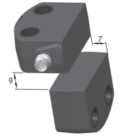 | 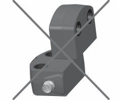 |
- Azionamento laterale solo del lato del sensore mostrato.
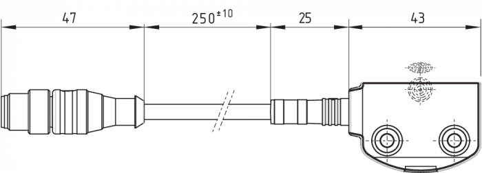
4.3 Dimensioni
Tutte le dimensioni sono in millimetri (mm).
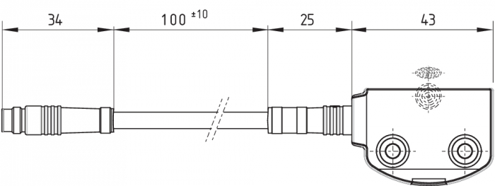
Sensore di sicurezza con cavo di collegamento integrato
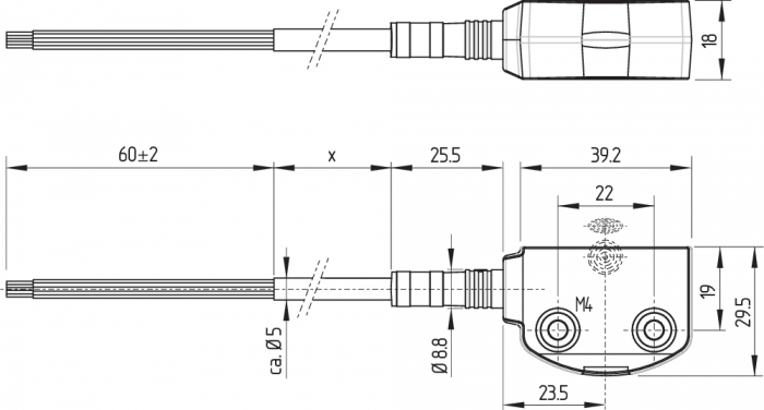
| Legenda | |
|---|---|
| x | Lunghezza cavo |
Sensore di sicurezza RSS260-...-ST

Sensore di sicurezza RSS260-...-LSTM 12
Sensore di sicurezza RSS260-...-LSTM 8
Azionatore RST260-1
| Legenda | |
|---|---|
 | area attiva |
- Per azionatori alternativi, con forme costruttive diverse, vedere products.schmersal.com.
4.4 Accessori
Set di viti di sicurezza antimanomissione (da ordinare separatamente)
- 4 pz. M4x25 incl. rondelle, codice d'ordine 101217746
- 4 pz. M4x30 incl. rondelle, codice d'ordine 101217747
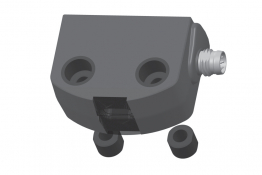
Set di guarnizioni (da ordinare separatamente)
- codice d'ordine 101215048
- 8 tappi e 4 guarnizioni
- per sigillare i fori di montaggio e come distanziale (circa 3mm) in modo da facilitare la pulizia al di sotto della superficie di montaggio
- utilizzabile anche come protezione anti-manomissione per viti di fissaggio
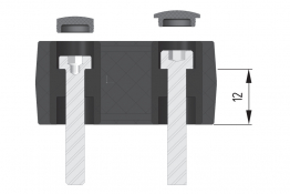 | 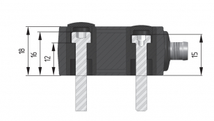 |  |
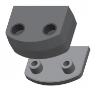
Kit di montaggio (da ordinare separatamente)
- Numero d'ordine 103005469
- Utilizzo alternativo di piastre di montaggio o manicotti
- Piastre di montaggio: 2 pezzi per il montaggio su superfici portanti non piane, ad esempio su profili scanalati
- Manicotti: 4 pezzi per fissare il fissaggio a vite alla superficie di montaggio in applicazioni con forti oscillazioni di temperatura
 |  |
4.5 intervallo di commutazione
La superficie laterale lunga permette un disallineamento massimo in altezza (X) tra sensore ed azionatore di ± 8 mm (ad es. tolleranza di montaggio o per abbassamento della porta di sicurezza). Lo scostamento trasversale (Y) è max. ± 18 mm.
Curve di avvicinamento
Le curve di avvicinamento mostrano le tipiche distanze di commutazione del sensore di sicurezza con l'avvicinamento dell'azionatore in funzione della direzione di azionamento.
| Disallineamento trasversale | Disallineamento in altezza |
|---|---|
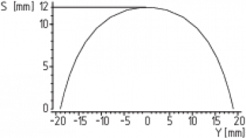 | 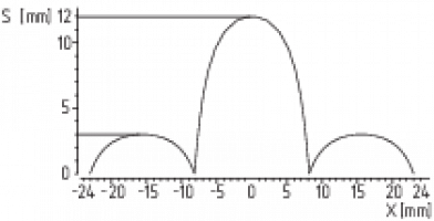 |
- Direzioni di azionamento preferibili: di fronte o lateralmente. In caso di azionamento laterale le distanze di commutazione si accorciano di ca. 3 mm.
4.6 Regolazione
Il LED giallo segnala il rilevamento dell'azionatore quando è permanentemente acceso e l'attivazione del sensore nella zona limite quando è lampeggiante.
- Regolazione consigliata
Allineare il sensore di sicurezza e l'azionatore a una distanza di 0,5 x sao.
Il funzionamento corretto di entrambi i canali di sicurezza deve essere infine verificato con il modulo di controllo di sicurezza collegato.
5 Collegamento elettrico
5.1 Note generali sul collegamento elettrico
- Il collegamento elettrico deve essere eseguito solo in condizioni di assenza di tensione e da personale specializzato autorizzato.
Le uscite di sicurezza possono essere utilizzate direttamente per il collegamento nel componente rilevante per la sicurezza dell'unità di controllo dell'utente. Per requisiti in PL e / Categoria 4 secondo EN ISO 13849-1, le uscite di sicurezza del sensore di sicurezza o della catena di sensori devono essere comandate con un modulo di controllo della stessa categoria.
La protezione elettrica richiesta per il cavo va prevista durante l'installazione.
In caso di posa assieme a cavi di controllo non è necessaria alcuna schermatura. Tuttavia si dovrà prestare attenzione a mantenere i cavi separati dai cavi di alimentazione e di potenza. La protezione max. di una catena di sensori da cortocircuiti dipende dalla sezione del cavo di collegamento dei sensori.
Requisiti per il modulo di controllo/diagnosi collegato:
ingresso di sicurezza a due canali, idoneo per sensori a commutazione p (positiva) con funzione NA.
- Per ulteriori informazioni sulla selezione dei moduli di controllo di sicurezza idonei si rimanda ai cataloghi Schmersal o al catalogo online disponibile in Internet all'indirizzo products.schmersal.com.
In alternativa al modulo di controllo è anche possibile utilizzare sensori di sicurezza delle serie RSS260…F0 o RSS260…F1 per il controllo diretto di porte di protezione di sicurezza come primo sensore di un azionamento in serie.
I sensori di sicurezza verificano le rispettive uscite di sicurezza mediante disattivazione ciclica. Non è invece richiesta la funzione di rilevamento cortocircuito. I tempi di disattivazione devono essere tollerati dal modulo di controllo. Il tempo di disattivazione del sensore di sicurezza si prolunga in funzione della lunghezza e della capacità del cavo utilizzato. Normalmente, con un cavo di collegamento di 30 m si raggiunge un tempo di disattivazione di 250 μs.
- Configurazione controllo di sicurezza
Se il sensore è collegato a moduli di controllo di sicurezza elettronici si raccomanda di impostare un tempo di discrepanza di almeno 100 ms. Gli ingressi di sicurezza del modulo di controllo devono essere in grado di escludere (blanking) un impulso di prova di ca. 1 ms. Non è invece richiesta la funzione di riconoscimento cortocircuito e, se presente, dovrà essere disattivata.
5.2 Diagnosi seriale -SD
Layout del cablaggio
Il cavo collegato al sensore di sicurezza non deve avere una capacità di linea superiore a 50 nF.
I normali cavi di controllo non schermati LIYY da 0,25 (0,14) mm² a 1,5 mm², a seconda della cordatura, presentano una capacità di linea di ca. 3 … 7 nF, per una lunghezza di 30 m.
- Nel cablaggio di dispositivi SD, prestare attenzione alla caduta di tensione sui cavi e alla capacità di carico di corrente dei singoli componenti.
- Accessori per azionamento in serie
Per un facile cablaggio e collegamento in serie di dispositivi SD sono disponibili i box di collegamento PFB-SD-4M12-SD (variante per il livello di campo) e PDM-SD-4CC-SD (variante per quadro elettrico, installabile su guida DIN), nonché svariati altri accessori. Per informazioni dettagliate, visitare il sito Internet products.schmersal.com.
5.3 Per esempi di collegamenti in serie
È possibile realizzare un azionamento in serie. In caso di collegamento in serie, il tempo di rischio rimane invariato e il tempo di reazione aumenta in misura pari alla somma dei tempi di reazione degli ingressi, riportati nei dati tecnici, per ciascun dispositivo aggiuntivo. Il numero dei dispositivi è limitato solo dalla protezione del cavo esterna, in base ai dati tecnici e alle perdite sul cavo ammissibili. Nel caso di dispositivi RSS260 … SD con funzione di diagnosi seriale è possibile collegare in serie fino a 31 unità.
Gli esempi applicativi qui rappresentati sono proposte che non esonerano l'utente dal controllare accuratamente l'idoneità del collegamento alla specifica applicazione.
Esempio di collegamento 1: Collegamento in serie di RSS260 con uscita di diagnosi convenzionale
La tensione viene alimentata sull'ultimo sensore di sicurezza della catena (visto dalla prospettiva del sistema di controllo a valle) ad entrambi gli ingressi di sicurezza.
Le uscite di sicurezza del primo sensore vengono indirizzate al dispositivo di controllo. L'uscita di diagnosi può essere collegata ad esempio ad un PLC.
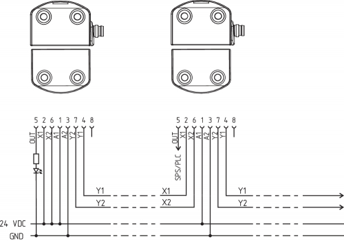
Y1 e Y2 = uscite di sicurezza -> modulo di controllo
Esempio di collegamento 2: Collegamento in serie di RSS260 con funzione di diagnosi seriale
Nei dispositivi con funzione di diagnosi seriale (indice d'ordine -SD), i collegamenti di diagnosi seriale sono commutati in serie e indirizzati per l'analisi a un gateway SD. La tensione viene alimentata sull'ultimo sensore di sicurezza della catena (visto dalla prospettiva del sistema di controllo a valle) ad entrambi gli ingressi di sicurezza.
Le uscite di sicurezza del primo sensore vengono indirizzate al dispositivo di controllo. Il gateway di diagnosi seriale è collegato all'ingresso di diagnosi seriale del primo sensore di sicurezza.

Y1 e Y2 = uscite di sicurezza -> modulo di controllo
SD-IN → Gateway → Bus di campo
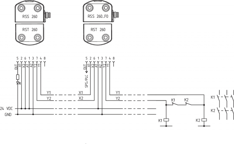
Esempio di collegamento 3: collegamento in serie con RSS260...F0
Il sensore di sicurezza RSS260...F0 controlla direttamente i contattori ausiliari o i relè azionati positivamente. Il monitoraggio dei contattori o relè esterni è consentito tramite il circuito di retroazione, costituito dei contatti NC di K1 e K2. Poiché non viene utilizzato nessun altro pulsante, i contattori ausiliari o relè si attivano immediatamente dopo la chiusura del dispositivo di protezione. Questo reset automatico è consentito solo se si può escludere un pericolo derivante dall'avvio della macchina.
Il circuito di retroazione può essere esteso da un pulsante di abilitazione. Il sensore si attiva non appena si aziona il pulsante. La struttura corrisponde quindi agli esempi di collegamento delle varianti F1. Il modulo di controllo interno della variante F0 non è dotato di sorveglianza del fronte per il pulsante. Se necessario, dovrà essere eseguito un "reset manuale" secondo EN ISO 13849-1 da altri componenti di un sistema di controllo locale.
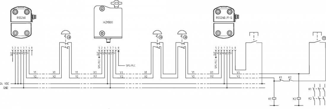
Esempio di collegamento 4: collegamento in serie con RSS260...F1-Q come master con EDM
Il sensore di sicurezza RSS260...F1 controlla direttamente i contattori ausiliari o i relè azionati positivamente. La funzione F1 sorveglia oltre ai contatti di retroazione anche la presenza di un fronte di discesa del pulsante di Reset. Il sensore si attiva rilasciando il pulsante. Può essere utilizzato per il reset manuale su dispositivi di protezione potenzialmente soggetti a manomissione. L'area protetta deve essere realizzata in modo che sia sufficiente un singolo pulsante di reset. La funzione Q sorveglia i pulsanti di arresto d'emergenza integrati nella catena e richiede un pulsante di conferma guasto/errore separato.

Esempio di collegamento 5: collegamento in serie con RSS260...SD-F1-Q come master con EDM e diagnostica seriale
Il sensore di sicurezza RSS260...F1 controlla direttamente contattori ausiliari o relè azionati positivamente. La funzione F1 sorveglia oltre ai contatti di retroazione anche la presenza di un fronte di discesa del pulsante di Reset. Il sensore si attiva rilasciando il pulsante. Può essere utilizzato per il reset manuale su dispositivi di protezione potenzialmente soggetti a manomissione. L'area protetta deve essere realizzata in modo che sia sufficiente un singolo pulsante di reset. La funzione Q sorveglia i pulsanti di arresto d'emergenza integrati nella catena. In caso di segnali di arresto d'emergenza non conformi, il messaggio di errore deve essere resettato attraverso il canale diagnostico seriale dalla sorveglianza Q.

Esempio di collegamento 6: collegamento in serie RSS260...F1-Q con componenti misti
Il sensore di sicurezza RSS260...F1 controlla direttamente i contattori ausiliari o i relè azionati positivamente. La funzione F1 sorveglia oltre ai contatti di retroazione anche la presenza di un fronte di discesa del pulsante di Reset. Il sensore si attiva rilasciando il pulsante. Può essere utilizzato per il reset manuale su dispositivi di protezione potenzialmente soggetti a manomissione. L'area protetta deve essere realizzata in modo che sia sufficiente un singolo pulsante di reset. La funzione Q sorveglia i pulsanti di arresto d'emergenza integrati nella catena e richiede un pulsante di conferma guasto/errore separato.
5.4 Assegnazione dei collegamenti e connettori accessori
- per sensori con cavo di collegamento integrato o connettore a 8 poli M8/M12, codifica A
| Funzione dispositivo di sicurezza | Assegnazione pin del connettore incorporato o del connettore con cavo M8/M12, 8 poli, codifica A | Codifica dei colori del cavo di collegamento integrato o dei connettori Schmersal | Possibile codifica dei colori di altri connettori in commercio Codice colore ulteriormente disponibile connettore | ||
|---|---|---|---|---|---|
| con uscita di diagnosi convenzionale | con funzione di diagnosi seriale |  | secondo DIN 47100 | secondo EN 60947-5-2 | |
| A1 | Ue | 1 | WH | BN | |
| X1 | Ingresso di sicurezza 1 | 2 | BN | WH | |
| A2 | GND | 3 | GN | BU | |
| Y1 | Uscita di sicurezza 1 | 4 | YE | BK | |
| OUT | Uscita di diagnosi | Uscita SD | 5 | GY | GY |
| X2 | Ingresso di sicurezza 2 | 6 | PK | PK | |
| Y2 | Uscita di sicurezza 2 | 7 | BU | VT | |
| IN | senza funzione / con opzione Q: Conferma errore | Ingresso SD | 8 | RD | OR |
- per sensori con connettore a 5 poli M12, codifica A
| Funzione dispositivo di sicurezza | Assegnazione pin del connettore con cavo M12, 5 poli, codifica A  | Possibile codifica dei colori di altri connettori in commercio Codifica dei colori di altri connettori in commercio secondo EN 60947-5-2 | |||
|---|---|---|---|---|---|
| A1 | Ue | 1 | BN | ||
| Y2 | Uscita di sicurezza 2 | 2 | WH | ||
| A2 | GND | 3 | BU | ||
| Y1 | Uscita di sicurezza 1 | 4 | BK | ||
| OUT | - | Uscita di diagnosi | solo per scopi interni, i segnali esterni vengono ignorati | 5 | GY |
| Cavi di collegamento con connettore (PUR) IP67, M8, 8 poli - 8 x 0,25 mm², dritto | |
|---|---|
| Lunghezza cavo | Codice articolo |
| 2 m | 103043259 |
| 5 m | 103043260 |
| 10 m | 103043261 |
| 15 m | 103043262 |
| Cavi di collegamento con connettore (femmina) IP67, M8, 8 poli - 8 x 0,25 mm², angolato | |
|---|---|
| Lunghezza cavo | Codice articolo |
| 2 m | 103043263 |
| 5 m | 103043264 |
| 10 m | 103043265 |
| Adattatore di collegamento (PUR) femmina M8 - maschio M12, IP67, 8 poli, 8 x 0,25 mm² | |
|---|---|
| Lunghezza cavo | Codice articolo |
| 2 m | 103003645 |
| Cavi di collegamento (PUR) con connettore (femmina) IP67 / IP69, M12, 5 poli, 5 x 0,34 mm², dritto | |
|---|---|
| Lunghezza cavo | Codice articolo |
| 5 m | 103010816 |
| 10 m | 103010818 |
| 15 m | 103010820 |
6 Codifica dell'azionatore
I sensori di sicurezza con codifica standard sono pronti per il funzionamento alla consegna.
Procedura per il reciproco rilevamento di sensori di sicurezza e azionatori con codifica personalizzata:
- Fornire la tensione di alimentazione al sensore di sicurezza.
- Portare l'azionatore nell'area di acquisizione. La procedura di rilevamento viene segnalata nel sensore di sicurezza con LED rosso acceso e LED giallo lampeggiante (1 Hz).
- Dopo 10 secondi, brevi impulsi lampeggianti gialli (3 Hz) indicano la necessità di disattivare la tensione d'esercizio del sensore di sicurezza. (Se entro 5 minuti non avviene alcuna disinserzione, il sensore di sicurezza interrompe la procedura di acquisizione e segnala un azionatore non corretto mediante lampeggiamento rosso ripetuto 5 volte.)
- Alla successiva inserzione della tensione d'esercizio l'azionatore dovrà essere nuovamente rilevato per attivare il codice acquisito dell'azionatore. Il codice attivato viene quindi salvato permanentemente.
Nell'opzione d'ordine -I1, l'assegnazione così effettuata di dispositivo di sicurezza e azionatore è irreversibile.
Nell'opzione d'ordine -I2 la procedura di acquisizione di un nuovo azionatore può essere ripetuta un numero illimitato di volte. Con l'acquisizione di un nuovo azionatore il precedente codice non è più valido. Inoltre un blocco di abilitazione di dieci minuti assicura una maggiore protezione da manomissione. Il LED verde lampeggia finché non è trascorso l'intervallo di blocco abilitazione ed il nuovo azionatore è stato acquisito. In caso di interruzione dell'alimentazione durante questo intervallo, il tempo di protezione antimanomissione di 10 minuti ricomincia da capo.
7 Principio d'azione e Funzione di diagnosi
7.1 Uscite di sicurezza
Le uscite di sicurezza possono essere utilizzate direttamente per il collegamento nel componente rilevante per la sicurezza dell'unità di controllo dell'utente.
L'apertura di una porta di sicurezza, cioè l'allontanamento dell'azionatore dalla zona attiva del sensore determina la disattivazione immediata delle uscite di sicurezza.
7.2 LED di diagnosi
Il sensore di sicurezza fornisce indicazioni sulle proprie condizioni d'esercizio e su eventuali guasti mediante i LED di segnalazione a tre colori disposti sui lati del sensore.
- Le seguenti segnalazioni a LED si applicano sia ai sensori di sicurezza con uscita di diagnosi convenzionale, sia a quelli con funzione di diagnosi seriale.
Il LED verde acceso segnala che il sensore è pronto per il funzionamento. La tensione di alimentazione è presente e tutti gli ingressi di sicurezza sono disponibili.
Un lampeggiamento (1 Hz) del LED verde segnala una mancanza di tensione su uno o su entrambi gli ingressi di sicurezza (X1 e/o X2).
Il LED giallo segnala un azionatore nel campo di rilevamento. Se l'azionatore si trova nella zona limite della distanza di commutazione del sensore, tale stato viene segnalato mediante lampeggiamento del LED.
Il lampeggiamento può essere utilizzato per rilevare tempestivamente una variazione nella distanza tra sensore ed azionatore (ad es. l'abbassamento di una porta di sicurezza). Si raccomanda di verificare l'installazione, prima che la distanza aumenti ulteriormente, di disinserire le uscite di sicurezza e di fermare la macchina. Se viene rilevato un errore, si accende il LED rosso.
| Indicatore LED (rosso) | Causa dell'errore | |
|---|---|---|
| 1 impulso intermittente |  | Errore all'uscita Y1 |
| 2 impulsi intermittenti |  | Errore all'uscita Y2 |
| 3 impulsi intermittenti |  | Cortocircuito Y1/Y2 |
| 4 impulsi intermittenti |  | Temperatura ambiente troppo elevata |
| 5 impulsi intermittenti |  | Azionatore non valido o difettoso |
| 6 impulsi intermittenti |  | Errore tempo di discrepanza su X1/X2 |
| Rosso continuo |  | Errore interno, con procedura di acquisizione lampeggiante in giallo |
7.3 Principio di funzionamento dell'uscita di diagnosi convenzionale
Ad integrazione, una uscita di diagnosi fornisce informazioni sullo stato operativo del dispositivo di sicurezza. I suoi segnali possono essere utilizzati da un eventuale modulo di controllo collegato a valle.
L'uscita diagnostica OUT a prova di cortocircuito può essere usata per la visualizzazione centrale o per task di controllo, ad es. in un PLC.
L'uscita di diagnosi non è un'uscita rilevante per la sicurezza!
Errore
Eventuali errori che compromettono il funzionamento sicuro del dispositivo di sicurezza (errori interni) determinano la disattivazione delle uscite di sicurezza nel tempo di rischio. Dopo la risoluzione dell'errore, il messaggio di errore viene resettato mediante apertura e richiusura della porta di sicurezza corrispondente.
Un errore di tempo di discrepanza viene memorizzato in modo fail-safe e deve essere resettato tramite conferma dell'errore.
Avvertenza di errore
Un errore che non compromette immediatamente il funzionamento sicuro del dispositivo di sicurezza (ad es. temperatura ambiente troppo elevata, uscita di sicurezza su potenziale esterno, cortocircuito trasversale) determina una disattivazione ritardata. Questa combinazione di segnali con "uscita di diagnosi disattivata" e "uscite di sicurezza ancora attive" può essere utilizzata per fermare la macchina in modo preordinato.
L'avvertenza di errore viene resettata quando la causa dell'errore è stata rimossa.
Se l'avvertenza di errore rimane attiva per 30 minuti, anche le uscite di sicurezza vengono disattivate (LED rosso lampeggiante).
| Tabella 1: Esempi per la funzione di diagnosi del sensore di sicurezza con uscita di diagnosi convenzionale | |||||||
|---|---|---|---|---|---|---|---|
| Funzione sensore | LED | Uscita di diagnosi | Uscite di sicurezza | Osservazione | |||
| verde | rosso | giallo | Y1, Y2 | ||||
| I. | Tensione di alimentazione | acceso | spento | spento | 0 V | 0 V | Tensione presente, nessuna valutazione della qualità della tensione |
| II. | azionato | spento | spento | acceso | 24 V | 24 V | Il LED giallo segnala sempre un azionatore nel campo di rilevamento. |
| III. | Azionato, azionatore nella zona limite | spento | spento | lampeggia | 24 V (ciclico) | 24 V | Il sensore deve essere regolato prima che la distanza dall'attuatore aumenti ulteriormente, disattivando le uscite di sicurezza e quindi arrestando la macchina. Frequenza di lampeggio 1 Hz |
| IV. | Errore interno o processo di teach-in con lampeggio giallo simultaneo | acceso | spento | lampeggia | 24 V | 0 V | Il sensore attende un segnale sul circuito di retroazione: F0: Chiusura del circuito di retroazione F1: Bordo di caduta sul circuito di retroazione Frequenza di lampeggio 5 Hz |
| V. | Azionato nell'area limite e circuito di retroazione aperto | acceso | spento | lampeggia | 24 V (ciclico) | 0 V | Il display a LED combina le funzioni del sensore III. e IV. Frequenza di lampeggiamento: alternata (1 Hz/5 Hz) |
| VI. | Segnalazione di errore, sensore attenuato | spento | lampeggia | acceso | 0 V | 24 V | Dopo 30 minuti errore |
| VII. | Guasto | spento | lampeggia | acceso | 0 V | 0 V | Vedere la tabella dei codici intermittenti |
| VIII. | Acquisizione azionatore | spento | acceso | lampeggia | 0 V | 0 V | Sensore in modo acquisizione |
| IX. | Tempo di protezione | lampeggia | spento | spento | 0 V | 0 V | Pausa di 10 minuti dopo riacquisizione |
| X. | Guasto nel circuito di ingresso X1 e/o X2 | lampeggia (1Hz) | spento | spento | 0 V | 0 V | Esempio: porta aperta; una porta precedente nel circuito di sicurezza è anch'essa aperta. |
| XI. | Guasto nel circuito di ingresso X1 e/o X2 | lampeggia (1Hz) | spento | acceso | 24 V | 0 V | Esempio: porta chiusa; una porta precedente nel circuito di sicurezza è aperta. |
7.4 Sensori di sicurezza con funzione di diagnosi seriale
I sensori di sicurezza con cavo di diagnosi seriale sono dotati, invece che dell'uscita di diagnosi convenzionale, di un ingresso e uscita seriali. Se i sensori di sicurezza RSS/CSS sono collegati in serie, oltre ai canali di sicurezza vengono commutati in serie anche gli ingressi e le uscite dei canali di diagnosi.
È possibile collegare in serie fino a 31 dispositivi di sicurezza con diagnosi seriale. Per la sorveglianza del cavo di diagnosi seriale si utilizza il gateway PROFIBUS SD-I-DP-V0-2 o il gateway universale SD-I-U-…. Questo gateway SD viene collegato come slave ad un sistema bus di campo disponibile. I segnali di diagnosi possono così essere analizzati con un PLC. Il software necessario per il collegamento dei gateway SD è disponibile in Internet all'indirizzo products.schmersal.com.
Le risposte e i dati di diagnosi per ciascun sensore di sicurezza collegato in serie vengono scritti in modo automatico e continuo in un byte di ingresso del PLC.
I dati di richiesta per ciascun sensore di sicurezza sono trasmessi invece attraverso un byte di uscita del PLC al dispositivo.
Se si verifica un errore di comunicazione tra il gateway SD e il sensore di sicurezza, il sensore di sicurezza mantiene il proprio stato di commutazione per le uscite di sicurezza.
Bit 0: Abilitazione uscite di sicurezza
Bit 1: Sensore di sicurezza smorzato, attuatore rilevato
Bit 3: Anello di retroazione aperto o pulsante di reset non azionato
Bit 4: Entrambi gli ingressi di sicurezza attivati
Bit 5: Sensore di sicurezza smorzato nel campo limite
Bit 6: Segnalazione di errore, ritardo di spegnimento attivo
Bit 7: Errore, uscite di sicurezza disattivate
Errore
Eventuali errori che compromettono il funzionamento sicuro del dispositivo di sicurezza (errori interni) determinano la disattivazione delle uscite di sicurezza nel tempo di rischio. L'errore viene resettato quando la relativa causa è stata rimossa e il bit 7 del byte di richiesta passa da 1 a 0 o la porta viene aperta. Eventuali errori alle uscite di sicurezza saranno resettati solo alla successiva abilitazione, perché la risoluzione dell'errore non può essere rilevata prima.
Gli errori di discrepanza vengono resettati quando il bit 6 del byte di chiamata passa da 1 a 0.
Avvertenza di errore
Un errore che non compromette immediatamente il funzionamento sicuro del dispositivo di sicurezza (ad es. temperatura ambiente troppo elevata, uscita di sicurezza su potenziale esterno, cortocircuito trasversale) determina una disattivazione ritardata. Questa combinazione di segnali con "uscita di diagnosi disattivata" e "uscite di sicurezza ancora attive" può essere utilizzata per fermare la macchina in modo preordinato.
L'avvertenza di errore viene resettata quando la causa dell'errore è stata rimossa.
Se l'avvertenza di errore rimane attiva per 30 minuti, anche le uscite di sicurezza vengono disattivate (LED rosso lampeggiante).
Errore/avvertenza di diagnosi
Se nel byte di risposta viene segnalato un errore/un'avvertenza, è possibile leggere informazioni dettagliate sull'errore.
| Tabella 2: Funzione dei LED di diagnosi, dei segnali di stato seriali e delle uscite di sicurezza (esempio) | ||||||||||||
|---|---|---|---|---|---|---|---|---|---|---|---|---|
| Stato del sistema | LED | Uscite di sicurezza | Segnali di stato byte di diagnosi seriale N. bit | |||||||||
| verde | rosso | giallo | Y1, Y2 | 7 | 6 | 5 | 4 | 3 | 2 | 1 | 0 | |
| Non azionato, ingressi X1 e X2 attivati | acceso | spento | spento | 0 V | 0 | 0 | 0 | 1 | 0 | 0 | 0 | 0 |
| Azionato, circuito di retroazione aperto / non azionato | acceso | spento | lampeggia (5Hz) | 0 V | 0 | 0 | 0 | 1 | 1 | 0 | 1 | 0 |
| Azionato, uscite di sicurezza abilitate | spento | spento | acceso | 24 V | 0 | 0 | 0 | 1 | 0 | 0 | 1 | 1 |
| Azionato, nella zona limite | spento | spento | lampeggia (1Hz) | 24 V | 0 | 0 | 1 | 1 | 0 | 0 | 1 | 1 |
| Azionato, avvertenza | spento | acceso/ lampeggia | acceso | 24 V | 0 | 1 | 0 | 1 | 0 | 0 | 1 | 1 |
| Azionato, errore | spento | acceso/ lampeggia | acceso | 0 V | 1 | 1 | 0 | 1 | 0 | 0 | 1 | 0 |
La sequenza di bit del byte di diagnosi sopra riportata è un esempio. In caso di diversa combinazione di più condizioni d'esercizio (stati operativi), si verificano delle variazioni nella sequenza dei bit. | ||||||||||||
| Tabella 3: Panoramica tabellare di segnali di stato, avvertenze o messaggi di errore (Stato descritto raggiunto, quando Bit = 1) | ||||
|---|---|---|---|---|
| Direzioni di comunicazione: | Byte di richiesta: | dal PLC al sensore di sicurezza locale | ||
| Byte di risposta: | dal sensore di sicurezza locale al PLC | |||
| Byte di avvertenza/errore: | dal sensore di sicurezza locale al PLC | |||
| N. bit | Byte di richiesta | Byte di risposta | Diagnosi | |
| Avviso di guasto | Messaggi di errore | |||
| Bit 0: | --- | Uscita di sicurezza attivata | Errore all'uscita Y1 | Errore all'uscita Y1 |
| Bit 1: | --- | Azionatore rilevati | Errore all'uscita Y2 | Errore all'uscita Y2 |
| Bit 2: | --- | --- | Cortocircuito Y1/Y2 | Cortocircuito Y1/Y2 |
| Bit 3: | --- | --- | Sovratemperatura | Sovratemperatura |
| Bit 4: | --- | Stato ingresso X1 e X2 | --- | Azionatore non valido o difettoso |
| Bit 5: | --- | Azionatore nella zona limite | Errore interno del dispositivo | Errore interno del dispositivo |
| Bit 6: | Conferma errore, superamento tempo di discrepanza | Avviso di guasto | Errore di comunicazione tra gateway bus di campo e dispositivo di commutazione di sicurezza | Errore Tempo di discrepanza superato su X1/X2 |
| Bit 7: | Reset errore | Errore (circuito di abilitazione disattivato) | --- | --- |
8 Messa in servizio e manutenzione
Il dispositivo di sicurezza deve essere testato per verificarne il corretto funzionamento. In caso di installazione corretta e utilizzo conforme, il dispositivo di sicurezza non richiede manutenzione. In normali circostanze, si raccomanda di eseguire un controllo visivo e funzionale secondo la procedura seguente:
- Verificare il corretto fissaggio del dispositivo di sicurezza e dell'azionatore.
- Integrità dei collegamenti dei cavi.
- Assenza di sporcizia all'interno del sistema (in particolare, trucioli metallici).
| Test funzionale dopo il montaggio e il collegamento del sensore RSS260…-F0/-F1 Prima dell'avvio del test, chiudere tutti i dispositivi di protezione. Il circuito di retroazione (feedback) deve essere aperto. 1) | |||
|---|---|---|---|
| N. | Azione per testare la funzionalità | Reazione RSS260 versione F0 | Reazione RSS260 versione F1 |
| 1 | Inserzione della tensione d'esercizio | Il LED giallo lampeggia a 5 Hz e i relè sono disattivati | Il LED giallo lampeggia a 5 Hz e i relè sono disattivati |
| 2 | Chiusura del circuito di retroazione: azionare il pulsante collegato 2) | Il LED giallo è acceso e i relè collegati sono entrambi attivatiIl LED giallo è acceso e i relè collegati sono entrambi attivati | Nessuna variazione rispetto a 1 |
| 3 | Solo versione F1: rilasciare il pulsante | Nessuna variazione rispetto a 2 | Il LED giallo è acceso e i relè collegati sono entrambi attivatiIl LED giallo è acceso e i relè collegati sono entrambi attivati |
| 1) Se non è utilizzato alcun pulsante, aprire il circuito di retroazione allentando il cavo. La tensione deve essere disattivata. 2) Se non si utilizza un pulsante, il circuito di retroazione deve essere chiuso ricollegando il cavo. Per questa operazione disinserire la tensione. | |||
Con la funzione F1, il pulsante monitorato per il fronte di discesa deve essere azionato.
Un pulsante non monitorato integrato nell'anello di retroazione con la funzione F0 è già efficace alla chiusura.
Gli elementi di commutazione E-STOP integrati in un collegamento in serie possono essere monitorati dalla funzione Q nell'ultimo sensore della catena. Questo controlla la disattivazione simultanea dei suoi ingressi di sicurezza e blocca le uscite di sicurezza in caso di deviazioni superiori a 500 ms. Un malfunzionamento della catena rilevato in questo modo deve essere eliminato immediatamente. Solo dopo la conferma dell'errore sarà possibile eseguire una nuova abilitazione. L'errore rimane memorizzato anche in caso di mancanza di tensione. Il guasto deve essere riconosciuto tramite il fronte negativo di un pulsante di conferma collegato al PIN 8 o tramite la linea diagnostica seriale.
In caso di integrazione di elementi di commutazione E-STOP, deve essere previsto anche un pulsante di reset, in quanto non è consentito il riavvio automatico della macchina dopo l'annullamento di un comando E-STOP.
A seconda dell'intervallo di test descritto nel capitolo sulla manutenzione, gli elementi di commutazione E-STOP così monitorati soddisfano i requisiti fino a PL e.
- In tutte le fasi del ciclo di vita operativo del dispositivo di commutazione di sicurezza è necessario intraprendere misure idonee da un punto di vista costruttivo ed organizzativo per la protezione antimanomissione o contro l'aggiramento del dispositivo di sicurezza, ad esempio mediante l'impiego di un azionatore sostitutivo.
- In caso di contattori di arresto d'emergenza integrati in un circuito in serie con monitoraggio Q si dovrà provvedere a verificarne il corretto funzionamento a intervalli regolari. Per un'applicazione normale di Cat. 3/PL d, è sufficiente un intervallo di controllo annuale. Per la Cat. 4/PL e, è necessario eseguire la verifica con frequenza mensile.
- Eventuali dispositivi danneggiati o difettosi dovranno essere sostituiti.
9 Smontaggio e smaltimento
9.1 Smontaggio
Smontare il dispositivo di sicurezza solo in assenza di tensione.
9.2 Smaltimento
- Smaltire il dispositivo di sicurezza in conformità con le disposizioni e le normative nazionali vigenti.
Schmersal Schweiz AG, Moosmattstraße 3, 8905 Arni
I dettagli e i dati qui riportati sono stati attentamente verificati. Le immagini possono differire dagli originali. Altri dati tecnici possono essere trovati nei manuali. Salvo modifiche tecniche o errori.
Generato il 09.05.2025, 11:17