RSS260-123456 Test

RSS260-123456 Test
- Universal kodning med RFID-teknologi
- 1 x forbindelsesprop M8
- aktivering forfra og fra siden mulig
- Kunstof hus
- Enkel montering
- Manipulationsbeskyttelse med RFID-teknologi, som dækker behovet
Bestillings data
| Tip (leveringsdygtighed) |
Leveres ikke længere! |
| Produkttypebetegnelse |
RSS260-123456 Test |
| Artikenummer (Bestillingsnummer) |
999999988 |
| EAN (European Article Number) |
4030661436418 |
| eCl@ss number, version 12.0 |
27-27-46-01 |
| eCl@ss number, version 11.0 |
27-27-24-03 |
| eCl@ss Nummer, Version 9.0 |
27-27-24-03 |
| ETIM number, version 7.0 |
EC001829 |
| ETIM number, version 6.0 |
EC001829 |
Globale egenskaber
| Forskrifter |
EN IEC 60947-5-3 |
| generel information |
Universel kodning |
| Kodningstrin ifølge EN ISO 14119 |
lav |
| Aktivt princip |
RFID |
| Konstruktionsform på hus |
Blok |
| Installationsforhold (mekaniske) |
ingen planmontering |
| Sensorens topologi |
Føler til serier forbindelse |
| Materiale til kapsling |
Kunststof, Termoplast, selvslukkende |
| Aktivt område |
Plastik, Thermoplastik |
| Reaktionstid, maksimum |
100 ms |
| Længde af risiko, maksimum |
200 ms |
| Bruttovægt |
47 g |
Generelle data - egenskaber
| Diagnoseudgang |
Ja |
| Kortslutningsregistrering |
Ja |
| Kortslutningsregistrering |
Ja |
| Sikkerhedsfunktionerne |
Ja |
| Kan kaskade |
Ja |
| Integreret display, status |
Ja |
| Antal LEDs |
3 |
| Antal halvlederudgange med signalfunktioner. |
1 |
| Antal afsikre digitale udgange |
2 |
Klassifikation
| At standardisere, Forskrifter |
EN ISO 13849-1 EN IEC 60947-5-3 EN IEC 62061 EN IEC 61508 |
| Performance Level, til |
e |
| Kategori iht. EN ISO 13849 |
4 |
| PFH-værdi |
6,80 x 10⁻¹⁰ /h |
| Safety Integrity Level (SIL), egnet i |
3 |
| Brugstid |
20 År |
Mekaniske data
| Aktuatorniveau |
på siden forside |
| Aktivt område |
på siden forside |
| Fastgørelse |
Til montering af sensorerne er normalt 20 mm skruelængde tilstrækkelig. Ved anvendelse af montageplader anbefales 25 mm skruer. |
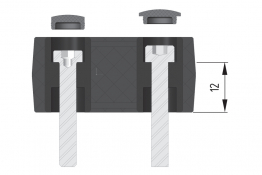
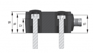
Mechanical data - Switching distances
| Afbryderdistance |
forside 12 mm på siden 9 mm |
| Sikret afbryderdistance ON Sao, front |
10 mm |
| Sikret afbryderdistance OFF Sar, front |
18 mm |
| Sikret afbryderdistance ON Sao, på siden |
6 mm |
| Sikret afbryderdistance OFF Sar, på siden |
15 mm |
| Note (switching distance) |
All switching distances in accordance EN IEC 60947-5-3 |
| Hyserese (afbryderdistance), maksimum |
2 mm |
| Gentagelsespræcision |
0,5 mm |
| Bemærk (gentagelsespræcision R) |
Akseludligning: Den lange sideflade tillader en maks. højdeforskydning (X) af sensor og aktuator på 8 mm (f.eks. monteringstolerance, eller hvis beskyttelsesdøren sænkes). Den tværgående forskydning (y) er maks. ± 18 mm (se illustration: driftsprincip)Mindsteafstand 100 mm ved sideværts tilgang |
Mekaniske data - Tilslutning
| Note (length of the sensor chain) |
Cable length and cross-section change the voltage drop dependiing on the output current |
| Tilslutning, Stik |
Forbindelse M8 |
Mekaniske data - afmåling
| Længde på føler |
29,5 mm |
| Bredde på føler |
39,2 mm |
| Højde på føler |
18 mm |
Omgivende forhold
| Beskyttelses klasse |
IP65 IP67 |
| Ambient temperature |
-25 ... +65 °C |
| Storage and transport temperature |
-25 ... +85 °C |
| Vibrationsstabilitet iht. EN 60068-2-6 |
10 … 55 Hz, amplitude 1 mm |
| Modstand over for slag |
30 g / 11 ms |
Omgivende forhold - Isolationsparametre
| Isolations spænding |
32 VDC |
| Fastsat impulsmodstandsspænding |
0,8 kV |
| Overspændingskategori |
III |
| Grad af forurening iht. VDE 0100 |
3 |
Elektrisk data
| Operating voltage |
24 VDC -15 % / +10 % |
| No-load supply current I0, typical |
100 mA |
| Rated operating voltage |
24 VDC |
| Forsyningsstrøm |
600 mA |
| Betinget kortslutningsstrøm iht. EN 60947-5-1 {A} |
100 A |
| Forsinkelse, maksimal |
2.000 ms |
| Afbryderfrekvens, cirka |
1 Hz |
| Utilisation category DC-12 |
24 VDC / 0,05 A |
Elektrisk data - sikre digitale udgange
| Version |
P-type |
| Spændingsfald Ud, maksimum |
1 V |
| Reststrøm |
0,5 mA |
| Spænding, brugskategori DC-12 |
24 VDC |
| Strøm, brugskategori DC-12 |
0,25 A |
| Spænding, brugskategori DC-13 |
24 VDC |
| Strøm, brugskategori DC-13 |
0,25 A |
Elektrisk data - diagnoseudgang
| Version |
P type |
| Spændingsfald Ud, maksimum |
2 V |
| Spænding, brugskategori DC-12 |
24 VDC |
| Strøm, brugskategori DC-12 |
0,05 A |
| Spænding, brugskategori DC-13 |
24 VDC |
| Strøm, brugskategori DC-13 |
0,05 A |
Elektrisk data - Elektromagnetisk kompatibilitet (EMV)
| Interferens |
IEC 61000-6-4 |
| EMC klassificering |
IEC 60947-3 |
Tilstandsvisning
| Bemærk (LED-tilstandsvisning) |
gul LED: Driftstilstand grøn LED: Forsyningsspænding rødt LED : Fejl |
Pin-tildeling
| PIN 1 |
A1 Ue: hvid |
| PIN 2 |
X1 Sikkerhedsindgang 1: brun |
| PIN 3 |
A2 GND: grøn |
| PIN 4 |
Y1 Sikkerhedsudgang 1: gul |
| PIN 5 |
OUT Diagnoseudgang OUT Grå |
| PIN 6 |
X2 Sikkerhedsindgang 2: pink |
| PIN 7 |
Y2 Sikkerhedsudgang 2: blå |
| PIN 8 |
IN uden funktion: rød |
Tilbehør
| Anbefalede (Aktuator) |
RST16-1 RST-U-2 RST260-1 |
| Anbefaling, sikkerhedsafbryder |
PROTECT PSC1 SRB-E-301ST SRB-E-201LC |
Sprog filter
Datablad
Driftsvejledning og Erklæring om konformitet
Brochure
SISTEMA-VDMA bibliotek/library
Hent sidste version af Adobe Reader
Produktbillede (katalogenkeltfoto)
Dimensionstegning, grundlæggende komponent
Video ID: RSS-260-01
Basic function (Vimeo)

Video ID: RSS-260-02
Variable mounting options (Vimeo)
Video ID: RSS-260-03
Single device connection (Vimeo)
Video ID: RSS-260-04
Series connection with serial diagnostics (Vimeo)
Video ID: RSS-260-05
Cross-fault with controlled shut-down process (Vimeo)
Video ID: RSS-260-06
Tolerance to misalignment (Vimeo)
Video ID: RSS-260-07
Warning when actuator is in limit range (Vimeo)
Video ID: RSS-260-11
RST-16-1 actuator on flat contour safety guards (Vimeo)
Video ID: RSS-260-12
RST-U-2 actuator for confined spaces (Vimeo)
Video ID: RSS260-13
Produktinformation RSS260 (Vimeo)
Indholdsfortegnelse
- 1 About this document
- 1.1 Function
- 1.2 Target group of the operating instructions: authorised qualified personnel
- 1.3 Explanation of the symbols used
- 1.4 Appropriate use
- 1.5 General safety instructions
- 2 Product description
- 2.1 Ordering code
- 2.2 Special versions
- 2.3 Purpose
- 2.4 Warning about misuse
- 2.5 Exclusion of liability
- 3 Technical data
- 4 Mounting
- 4.1 General mounting instructions
- 4.2 Actuating directions
- 4.3 Dimensions
- 4.4 Accessories
- 4.5 Switch distance
- 4.6 Adjustment
- 5 Electrical connection
- 5.1 General information for electrical connection
- 5.2 Serial diagnostic -SD
- 5.3 Wiring examples for series-wiring
- 5.4 Wiring configuration and connector accessories
- 6 Actuator coding
- 7 Working principle and diagnostic function
- 7.1 Mode of operation of the safety outputs
- 7.2 Diagnostic-LEDs
- 7.3 Operating principle of the electronic diagnostic output
- 7.4 Safety-sensors with serial diagnostic function
- 8 Set-up and maintenance
- 9 Disassembly and disposal
- 9.1 Disassembly
- 9.2 Disposal
1 About this document
1.1 Function
This document provides all the information you need for the mounting, set-up and commissioning to ensure the safe operation and disassembly of the switchgear. The operating instructions enclosed with the device must always be kept in a legible condition and accessible.
1.2 Target group of the operating instructions: authorised qualified personnel
All operations described in the operating instructions manual must be carried out by trained specialist personnel, authorised by the plant operator only.
Please make sure that you have read and understood these operating instructions and that you know all applicable legislations regarding occupational safety and accident prevention prior to installation and putting the component into operation.
The machine builder must carefully select the harmonised standards to be complied with as well as other technical specifications for the selection, mounting and integration of the components.
The information contained in this operating instructions manual is provided without liability and is subject to technical modifications.
1.3 Explanation of the symbols used
- Information, hint, note: This symbol is used for identifying useful additional information.
- Caution: Failure to comply with this warning notice could lead to failures or malfunctions.
Warning: Failure to comply with this warning notice could lead to physical injury and/or damage to the machine.
1.4 Appropriate use
The Schmersal range of products is not intended for private consumers.
The products described in these operating instructions are developed to execute safety-related functions as part of an entire plant or machine. It is the responsibility of the manufacturer of a machine or plant to ensure the correct functionality of the entire machine or plant.
The safety switchgear must be exclusively used in accordance with the versions listed below or for the applications authorised by the manufacturer. Detailed information regarding the range of applications can be found in the chapter "Product description".
1.5 General safety instructions
The user must observe the safety instructions in this operating instructions manual, the country specific installation standards as well as all prevailing safety regulations and accident prevention rules.
- Further technical information can be found in the Schmersal catalogues or in the online catalogue on the Internet: products.schmersal.com.
2 Product description
2.1 Ordering code
| Product type description: RSS260-(1)-(2)-(3)-(4)-(5) |
| (1) | |
| without | Standard coding |
| I1 | Individual coding |
| I2 | Individual coding, multiple teaching |
| (2) | |
| D | With diagnostic output |
| SD | With serial diagnostic function |
| (3) | |
| without | Standard version without feedback circuit monitoring EDM (External Device Monitoring) |
| F0 | EDM with automatic reset |
| F1 | EDM with manual reset |
| (4) | |
| without | Without EMERGENCY STOP |
| Q | Acknowledge input error with EMERGENCY STOP |
| (5) | |
| without | Connecting cable (lenght in m) |
| ST | Connector plug M8, 8-pole |
| LSTM12-8-0,25M | Cable 0.25 m long with connector M12, 8-pole |
| LSTM8-8-0,1M | Cable 0.1 m long with connector M8, 8-pole |
| LSTM12-5-0.25M | Cable 0.25 m long with connector M12, 5-pole |
2.2 Special versions
For special versions, which are not listed in the ordering code, these specifications apply accordingly, provided that they correspond to the standard version.
2.3 Purpose
This non-contact, electronic safety sensor is designed for application in safety circuits and is used for monitoring the position of movable safety guards. In this application, the safety sensor monitors the position of hinged, sliding or removable safety guards by means of the coded electronic actuator.
The safety function consists of safely switching off the safety outputs when the safety guard is opened and maintaining the safe switched off condition of the safety outputs for as long as the safety guard is open.
- The safety switchgears are classified according to EN ISO 14119 as type 4 interlocking devices. Designs with individual coding are classified as highly coded.
With the F0/F1 option, the sensor performs the tasks of a safety-monitoring module. At both safety outputs, two auxiliary contactors1) or Relays1) (1) each with positive-action contacts in accordance with EN 60947-5-1 or EN 50205) can be connected, whose safety-related function is checked by the sensor by means of a feedback circuit (External Device Monitoring). The feedback circuit includes the series-wiring of the NC contacts of the auxiliary contactors or relays. For the F0 version, an "enabling switch" (without safety function) can be integrated into the feedback circuit. For the F1 version, a so-called "reset button" is required, which is monitored for a trailing edge. This function corresponds to the "manual reset function" to EN ISO 13849-1.
The Q option monitors simultaneous shutdown of the sensor inputs. Series-wired sensors enable integration of EMERGENCY STOP switching elements for applications to PLe. The EMERGENCY STOP contacts are supplied by the cross-circuit monitored output signals of an upstream electronic safety switchgear device. At the end of the chain, a sensor with Q option for connecting an acknowledgement function monitors the chain for synchronous shutdown of both channels. In the event of erroneous shutdown, the error must be rectified. The safety outputs can be reactivated only once the error has been acknowledged.
The diagnostic output of the safety sensor alternatively can be used as a conventional output or as a “serial output“ with input and output channel.
Series-wiring can be set up. In the case of a series connection, the risk time remains unchanged and the reaction time increases by the sum of the reaction time of the inputs per additional unit specified in the technical data. The quantity of devices is only limited by the cable drops and the external cable fuse protection, according to the technical data. Up to 31 device variants with serial diagnostics can be wired in series.
- The user must evaluate and design the safety chain in accordance with the relevant standards and the required safety level. If multiple safety sensors are involved in the same safety function, the PFH values of the individual components must be added.
- The entire concept of the control system, in which the safety component is integrated, must be validated to the relevant standards.
2.4 Warning about misuse
- In case of improper use or manipulation of the safety switchgear, personal hazards or damages to machinery or plant components cannot be excluded. There are no residual risks, provided that the safety instructions as well as the instructions regarding mounting, commissioning, operation and maintenance are observed.
2.5 Exclusion of liability
We shall accept no liability for damages and malfunctions resulting from defective mounting or failure to comply with the operating instructions manual. The manufacturer shall accept no liability for damages resulting from the use of unauthorised spare parts or accessories.
For safety reasons, invasive work on the device as well as arbitrary repairs, conversions and modifications to the device are strictly forbidden, the manufacturer shall accept no liability for damages resulting from such invasive work, arbitrary repairs, conversions and/or modifications to the device.
3 Technical data
| Standards | EN ISO 13849-1, EN ISO 14119, EN IEC 60947-5-3, EN IEC 61508 |
| Coding level according to EN ISO 14119 | Low |
| Coding level according to EN ISO 14119 | High |
| Working principle | RFID |
| Frequency band RFID | 125 kHz |
| Transmitter output RFID, maximum | -6 dB/m |
| Time to readiness, maximum | 5000 ms |
| Duration of risk, maximum | 200 ms |
| Reaction time, switching off safety outputs via actuator, maximum | 100 ms |
| Reaction time, switching off safety outputs via safety inputs, maximum | 1.5 ms |
| IP rating | IP66, IP67, IP69 |
| Standards | EN ISO 13849-1, EN IEC 61508 |
| Performance Level, up to | e |
| Control category | 4 |
| PFH-value | 0.00000000052 /h |
| PFD value | 0.000045 |
| Safety Integrity Level (SIL), suitable for application in | 3 |
| Usage duration | 20 years |
| Performance Level, up to | d |
| Control category | 2 |
| PFH-value | 2.00 x 10⁻⁹ /h |
| PFD value | 1.80 x 10⁻⁴ |
| Safety Integrity Level (SIL), suitable for application in | 2 |
| Usage duration | 20 years |
| Mechanical lifetime, minimum | 1000000 operations |
| Note: (Mechanical lifetime) | When using as door hinge: ≥ 50,000 operations (Türmassen ≤ 5 kg and actuating speed ≤ 0.5 m/s) |
| Angular misalignment between solenoid interlock and actuator, maximum | 2 ° |
| Holding force Fmax, maximum | 1500 N |
| Holding force FZh to EN ISO 14119 | 1150 N |
| Latching force (position 1 / position 2) | 25 N / 50 N |
| Type of the fixing screws | 2x M6 |
| Tightening torque for the fixing screws | 6 ... 7 Nm |
| Switching distance, typically | 2 mm |
| Assured switching distance "ON" Sao | 1 mm |
| Assured switching distance "OFF" Sar | 20 mm |
| Termination | Connector plug M12, 8-pole, A-coded |
| Length of the Sensor chain, maximum | 200 m |
| Notice (Length of the sensor chain) | Cable length and cable section alter the voltage drop depending on the output current |
| Notice (Series-wiring) | Unlimited number of components, please observe external cable protection, max. 31 components in case of serial diagnostics SD |
| Operating Voltage | 24 VDC -15% / +10% (stabilised PELV) |
| No-load current I0, typically | 100 mA |
| Current consumption with magnet ON, average | 200 mA |
| Current consumption with magnet ON, peak | 350 mA / 200 ms |
| Required rated short-circuit current | 100 A |
| External cable and device fuse rating | 2 A gG |
| Switching frequency, maximum | 0.5 Hz |
| Designation, Magnet control | IN |
| Switching thresholds | -3 V … 5 V (Low) 15 V … 30 V (High) |
| Current consumption at 24 V | 10 mA |
| Test pulse duration, maximum | 5 ms |
| Test pulse interval, minimum | 40 ms |
| Designation, Safety inputs | X1 and X2 |
| Switching thresholds | −3 V … 5 V (Low) 15 V … 30 V (High) |
| Current consumption at 24 V | 5 mA |
| Test pulse duration, maximum | 1 ms |
| Test pulse interval, minimum | 100 ms |
| Designation, Safety outputs | Y1 and Y2 |
| Design of control elements | short-circuit proof, p-type |
| Voltage drop Ud, maximum | 2 V |
| Leakage current Ir, maximum | 0.5 mA |
| Utilisation category DC-12 | 24 VDC / 0.25 A |
| Utilisation category DC-13 | 24 VDC / 0.25 A |
| Test pulse duration, maximum | 0.5 ms |
| Test pulse interval, typical | 1000 ms |
| Designation, diagnostic outputs | OUT |
| Design of control elements | short-circuit proof, p-type |
| Voltage drop Ud, maximum | 2 V |
| Utilisation category DC-13 | 24 VDC / 0.05 A |
| Designation, Serial diagnostic SD | OUT |
| Design of control elements | short-circuit proof, p-type |
| Operating current | 150 mA |
| Wiring capacitance | 50 nF |
| Utilisation category DC-12, diagnostic output | 24 VDC / 0.05 A |
Globale egenskaber
| Forskrifter |
EN IEC 60947-5-3 |
| generel information |
Universel kodning |
| Kodningstrin ifølge EN ISO 14119 |
lav |
| Aktivt princip |
RFID |
| Konstruktionsform på hus |
Blok |
| Installationsforhold (mekaniske) |
ingen planmontering |
| Sensorens topologi |
Føler til serier forbindelse |
| Materiale til kapsling |
Kunststof, Termoplast, selvslukkende |
| Aktivt område |
Plastik, Thermoplastik |
| Reaktionstid, maksimum |
100 ms |
| Længde af risiko, maksimum |
200 ms |
| Bruttovægt |
47 g |
Generelle data - egenskaber
| Diagnoseudgang |
Ja |
| Kortslutningsregistrering |
Ja |
| Kortslutningsregistrering |
Ja |
| Sikkerhedsfunktionerne |
Ja |
| Kan kaskade |
Ja |
| Integreret display, status |
Ja |
| Antal LEDs |
3 |
| Antal halvlederudgange med signalfunktioner. |
1 |
| Antal afsikre digitale udgange |
2 |
Klassifikation
| At standardisere, Forskrifter |
EN ISO 13849-1 EN IEC 60947-5-3 EN IEC 62061 EN IEC 61508 |
| Performance Level, til |
e |
| Kategori iht. EN ISO 13849 |
4 |
| PFH-værdi |
6,80 x 10⁻¹⁰ /h |
| Safety Integrity Level (SIL), egnet i |
3 |
| Brugstid |
20 År |
Mekaniske data
| Aktuatorniveau |
på siden forside |
| Aktivt område |
på siden forside |
| Fastgørelse |
Til montering af sensorerne er normalt 20 mm skruelængde tilstrækkelig. Ved anvendelse af montageplader anbefales 25 mm skruer. |
Mechanical data - Switching distances
| Afbryderdistance |
forside 12 mm på siden 9 mm |
| Sikret afbryderdistance ON Sao, front |
10 mm |
| Sikret afbryderdistance OFF Sar, front |
18 mm |
| Sikret afbryderdistance ON Sao, på siden |
6 mm |
| Sikret afbryderdistance OFF Sar, på siden |
15 mm |
| Note (switching distance) |
All switching distances in accordance EN IEC 60947-5-3 |
| Hyserese (afbryderdistance), maksimum |
2 mm |
| Gentagelsespræcision |
0,5 mm |
| Bemærk (gentagelsespræcision R) |
Akseludligning: Den lange sideflade tillader en maks. højdeforskydning (X) af sensor og aktuator på 8 mm (f.eks. monteringstolerance, eller hvis beskyttelsesdøren sænkes). Den tværgående forskydning (y) er maks. ± 18 mm (se illustration: driftsprincip)Mindsteafstand 100 mm ved sideværts tilgang |
Mekaniske data - Tilslutning
| Note (length of the sensor chain) |
Cable length and cross-section change the voltage drop dependiing on the output current |
| Tilslutning, Stik |
Forbindelse M8 |
Mekaniske data - afmåling
| Længde på føler |
29,5 mm |
| Bredde på føler |
39,2 mm |
| Højde på føler |
18 mm |
Omgivende forhold
| Beskyttelses klasse |
IP65 IP67 |
| Ambient temperature |
-25 ... +65 °C |
| Storage and transport temperature |
-25 ... +85 °C |
| Vibrationsstabilitet iht. EN 60068-2-6 |
10 … 55 Hz, amplitude 1 mm |
| Modstand over for slag |
30 g / 11 ms |
Omgivende forhold - Isolationsparametre
| Isolations spænding |
32 VDC |
| Fastsat impulsmodstandsspænding |
0,8 kV |
| Overspændingskategori |
III |
| Grad af forurening iht. VDE 0100 |
3 |
Elektrisk data
| Operating voltage |
24 VDC -15 % / +10 % |
| No-load supply current I0, typical |
100 mA |
| Rated operating voltage |
24 VDC |
| Forsyningsstrøm |
600 mA |
| Betinget kortslutningsstrøm iht. EN 60947-5-1 {A} |
100 A |
| Forsinkelse, maksimal |
2.000 ms |
| Afbryderfrekvens, cirka |
1 Hz |
| Utilisation category DC-12 |
24 VDC / 0,05 A |
Elektrisk data - sikre digitale udgange
| Version |
P-type |
| Spændingsfald Ud, maksimum |
1 V |
| Reststrøm |
0,5 mA |
| Spænding, brugskategori DC-12 |
24 VDC |
| Strøm, brugskategori DC-12 |
0,25 A |
| Spænding, brugskategori DC-13 |
24 VDC |
| Strøm, brugskategori DC-13 |
0,25 A |
Elektrisk data - diagnoseudgang
| Version |
P type |
| Spændingsfald Ud, maksimum |
2 V |
| Spænding, brugskategori DC-12 |
24 VDC |
| Strøm, brugskategori DC-12 |
0,05 A |
| Spænding, brugskategori DC-13 |
24 VDC |
| Strøm, brugskategori DC-13 |
0,05 A |
Elektrisk data - Elektromagnetisk kompatibilitet (EMV)
| Interferens |
IEC 61000-6-4 |
| EMC klassificering |
IEC 60947-3 |
Tilstandsvisning
| Bemærk (LED-tilstandsvisning) |
gul LED: Driftstilstand grøn LED: Forsyningsspænding rødt LED : Fejl |
Pin-tildeling
| PIN 1 |
A1 Ue: hvid |
| PIN 2 |
X1 Sikkerhedsindgang 1: brun |
| PIN 3 |
A2 GND: grøn |
| PIN 4 |
Y1 Sikkerhedsudgang 1: gul |
| PIN 5 |
OUT Diagnoseudgang OUT Grå |
| PIN 6 |
X2 Sikkerhedsindgang 2: pink |
| PIN 7 |
Y2 Sikkerhedsudgang 2: blå |
| PIN 8 |
IN uden funktion: rød |
UL notice
- For use in NFPA 79 applications. Adapters that enable field wiring are available from the manufacturer. Observe the manufacturer's information. For use in Pollution Degree 2 Environment.
FCC/IC - Note
This device complies with Part 15 of the FCC Rules and contains licence-exempt transmitter/receivers that are compliant with ISED (Innovation, Science and Economic Development) Canada licence-exempt RSS standard(s).
Operation is subject to the following two conditions:
(1) This device may not cause harmful interference signals, and
(2) This device must be able to tolerate interference signals. These also include interference signals that could cause the device to function improperly.
This device complies with the nerve stimulation limits (ISED SPR-002) when operated at a minimum distance of 100 mm. Changes or modifications not expressly approved by K.A. Schmersal GmbH & Co. KG could void the user's authority to operate the equipment.
The licence-free transmitter/receiver contained in this device satisfies the requirements of the "Radio Standards Specification" of the Innovation, Science and Economic Development Canada (ISED) authority that apply to licence-free radio equipment. Operation is permissible under the following two conditions:
(1) The device must not create disturbances.
(2) The device must tolerate received radio frequency interference, even if this could impair its functionality.
This device complies with the nerve stimulation limits (ISED CNR-102) when operated at a minimum distance of 100 mm.
In the event of changes or modifications that have not been expressly approved by K.A. Schmersal GmbH & Co. KG, the user's authorisation to use the device may become ineffective.
| 20941-22-14519 | Este equipamento nao tem direito àprotecao contra interferência prejudicial e nao pode causar interferencia em sistemas devidamente autorizados. Para maiores informacores consultar: www.gov.br/anatel |
4 Mounting
4.1 General mounting instructions
- During fitting, the requirements of EN ISO 12100, EN ISO 14119 and EN ISO 14120 must be observed.
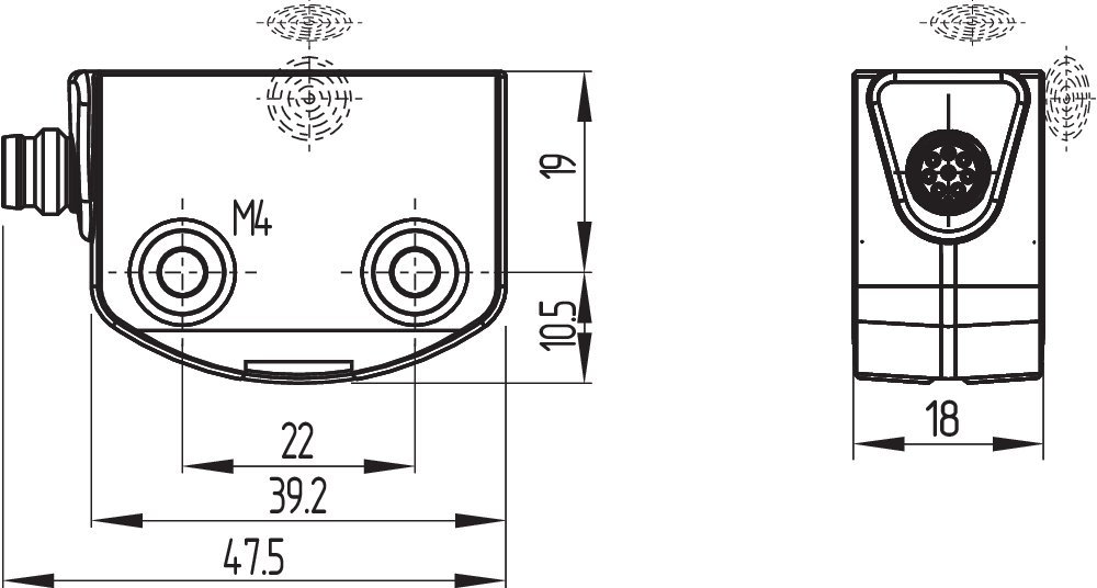
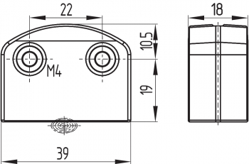
The mounting holes provide for a variable mounting by means of M4 screws (max. tightening torque 0.8 Nm). The component can be mounted in any position. The minimum bend radius of the cable- resp. LST-variants is 25 mm.
The active areas of the sensor and the actuator have to face each other. The safety sensor must only be used within the assured switching distances ≤ sao and ≥ sar.
- The actuator must be permanently fitted to the safety guards and protected against displacement by suitable measures (tamperproof screws, gluing, drilling of the screw heads).
To avoid any interference inherent to this kind of system and any reduction of the switching distances, please observe the following guidelines:
- The presence of metal chips in the vicinity of the sensor is liable to modify the switching distance.
- Keep away from metal chips
Minimum distance between two safety sensors as well as other systems with same frequency (125 kHz):

4.2 Actuating directions
| Actuation from front | Actuation from side | |
|---|---|---|
 |  |  |
- Lateral actuation only from the shown sensor side
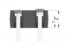
4.3 Dimensions
All measurements in mm.
Safety sensor with integrated cable

| Key | |
|---|---|
| x | Cable length |
Safety sensor RSS260-...-ST

Safety sensor RSS260-...-LSTM12
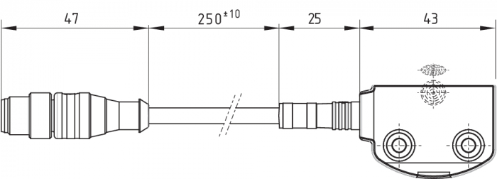
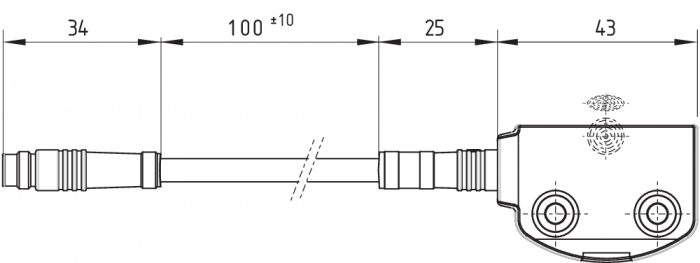
Safety sensor RSS260-...-LSTM8
Actuator: RST260-1
| Key | |
|---|---|
 | active area |
- Alternative suitable actuators with different design: refer to products.schmersal.com.
4.4 Accessories
Set of disposable screws (order separately)
- 4x M4x25 incl. washers, order number 101217746
- 4x M4x30 incl. washers, Bestellnummer 101217747
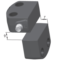
Sealing kit (order separately)
- Order number 101215048
- 8 plugs and 4 under seals
- To seal the mounting holes and as a spacer (approx. 3 mm) to facilitate cleaning below the mounting surface
- Also suitable as tamper protection for the screw attachment
 |  |  |
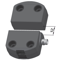
Assembly kit (to be ordered separately)
- ordering number 103005469
- Alternative use of mounting plates or ferrules
- Mounting plates: 2x for assembly on non-flat surfaces, e.g. on grooved profiles
- Ferrules: 4x for insertion to secure the screw fixings to the mounting surface for applications with regular high temperature variations
 |  |
4.5 Switch distance
The side allows for a maximum height misalignment (X) of sensor and actuator of ± 8 mm (e.g. mounting tolerance or due to guard door sagging). The axial misalignment (y) is max. ± 18 mm.
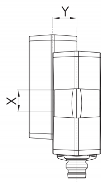
Actuating curves
The actuating curves represent the typical switching distance of the safety sensor during the approach of the actuator subject to the actuating direction
| Transverse misalignment | Height misalignment |
|---|---|
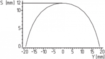 | 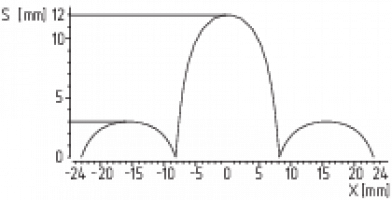 |
- Preferred actuation directions: from front or from side In case of a lateral actuation, the switching distances are reduced by approx. 3 mm.
4.6 Adjustment
The continuous signal of the yellow LED signals the actuator detection; the flashing of the yellow LED signals that the safety sensor is actuated in the hysteresis area.
- Recommended Adjustment
Align the safety sensor and actuator at a distance of 0.5 x sao.
The correct functionality of both safety channels must be checked by means of the connected safety-monitoring module.
5 Electrical connection
5.1 General information for electrical connection
- The electrical connection may only be carried out by authorised personnel in a de-energised condition.
The safety outputs can be integrated into the safety circuit of the control system. For applications of PL e / category 4 to EN ISO 13849-1, the safety outputs of the safety sensor or of the sensor chain must be wired to a safety monitoring-module of the same category.
The required electrical cable fuse protection must be integrated in the installation.
Protection is not required when pilot wires are laid. The cables however must be separated from the supply and energy cables. The max. fuse rate for a sensor chain depends on the section of the connecting cable of the sensor.
Requirements for the connected safety-monitoring module:
dual-channel safety input, suitable for p-type sensors with NO function
- Information for the selection of suitable safety-monitoring modules can be found in the Schmersal catalogues or in the online catalogue on the Internet: products.schmersal.com
As an alternative to an evaluation unit, the safety sensors of the RSS260..F0 resp. RSS260...F1 series can also be used for direct control and monitoring of safety contactors as first sensor of a series-wired chain.
The sensors cyclically switch off the safety output to test them. The safety-monitoring module therefore does not need to be equipped with a cross-wire short detection. The switch-off times must be tolerated by the safety-monitoring module. The switch -off time of the safety sensor is additionally extended depending on the cable length and the capacity of the cable used. Typically, a switch-off time of 250 μs is reached with a 30-m connecting cable.
- Configuration of the safety-monitoring module
If the safety sensor is connected to electronic safety-monitoring modules, we recommend that you set a discrepancy time of min. 100 ms. The safety inputs of the safety-monitoring module must be able blanking a test impulse of approx. 1 ms. The safety-monitoring module does not need to have a cross-wire short monitoring function, if necessary, the cross-wire short monitoring function must be disabled.
5.2 Serial diagnostic -SD
Cable design
The wiring capacitance of the connecting cable of the safety sensor must not exceed 50 nF.
Depending on the strand structure, normal unshielded 30 m long control cables LIYY 0.25 (0.14) mm² to 1.5 mm² have a wiring capacitance of approx. 3 … 7 nF.
- On wiring SD devices, please pay attention to the voltage drop on the cables and the current carrying capacity of the individual components.
- Accessories for the series-wiring
For convenient wiring and series-wiring of SD components, the SD junction boxes PFB-SD-4M12-SD (variant for the field) and PDM-SD-4CC-SD (variant for control cabinet on carrier rail) are available along with additional comprehensive accessories. Detailed information is available on the Internet, products.schmersal.com.
5.3 Wiring examples for series-wiring
Series-wiring can be set up. In the case of a series connection, the risk time remains unchanged and the reaction time increases by the sum of the reaction time of the inputs per additional unit specified in the technical data. The number of components is only limited by the external cable protection according to the technical data and the line loss. Series-wiring of up to 31 RSS260 … SD components with serial diagnostics is possible.
The application examples shown are suggestions. They however do not release the user from carefully checking whether the switchgear and its set-up are suitable for the individual application. The application examples shown are suggestions.
Wiring example 1: Series-wiring of the RSS 260 with conventional diagnostic output
The voltage is supplied to both safety inputs of the last safety sensor of the chain (considered from the safety-monitoring module).
The safety outputs of the first safety sensor are wired to the safety-monitoring module. The diagnostic output can be connected for instance to a PLC.
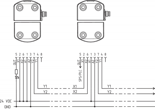
Y1 and Y2 = Safety outputs → Safety monitoring module
Wiring example 2: series-wiring of the RSS 260 with serial diagnostic function
In devices with the serial diagnostics function (ordering suffix -SD), the serial diagnostics connections are wired in series and connected to a SD-Gateway for evaluation purposes. The voltage is supplied to both safety inputs of the last safety sensor of the chain (considered from the safety-monitoring module).
The safety outputs of the first safety sensor are wired to the safety-monitoring module. The serial Diagnostic Gateway is connected to the serial diagnostic input of the first safety sensor.
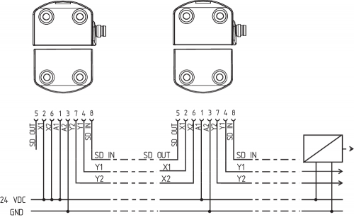
Y1 and Y2 = Safety outputs → Safety monitoring module
SD-IN → Gateway → Field bus
Wiring example 3: Series-wiring with RSS260…F0
The safety sensor RSS 260 ...F0 directly controls positive-action auxiliary contactors or relays. The monitoring of the external contactors or relays is enabled by the feedback circuit, which is built by the NC contacts of K1, K2. As no further button is used, the auxiliary contactors or relays are immediately enabled when the safety guard is closed. This kind of automatic reset is permissible only if a hazard from the machine starting up can be ruled out.
The feedback circuit can be extended by an enabling button. The sensor is switched on, as soon as the enabling button is pushed. The design then corresponds analogously to the wiring examples of the F1 variants The internal safety-monitoring module of variant F0 is not equipped with an edge detection for the button. If required, a "manual reset" to EN ISO 13849-1 must be realised by other components of a local control system.

Wiring example 4: Series-wiring with RSS260…F1-Q as master with EDM
The safety sensor RSS 260...F1 directly controls positive-action auxiliary contactors or relays. The F1 function also monitors a trailing edge of the reset button in addition to the feedback contacts. The sensor switches on when the button is released. It can be used for manual reset on safety guards, which can be stepped over. The protected area must be designed so that a single reset button suffices. The Q function monitors EMERGENCY STOP buttons integrated into the chain and requires a separate error acknowledgement button.

Wiring example 5: Series-wiring with RSS260…SD-F1-Q as master with EDM and serial diagnostics
The safety sensor RSS 260...F1 directly controls positive-action auxiliary contactors or relays. The F1 function also monitors a trailing edge of the reset button in addition to the feedback contacts. The sensor switches on when the button is released. It can be used for manual reset on safety guards, which can be stepped over. The protected area must be designed so that a single reset button suffices. The Q function monitors the EMERGENCY STOP buttons integrated into the chain. In the event of erroneous EMERGENCY STOP signals, the error message must be reset via the serial diagnostic channel using Q monitoring

Wiring example 6: Series-wiring with RSS260…F1-Q with mixed components
The safety sensor RSS 260...F1 directly controls positive-action auxiliary contactors or relays. The F1 function also monitors a trailing edge of the reset button in addition to the feedback contacts. The sensor switches on when the button is released. It can be used for manual reset on safety guards, which can be stepped over. The protected area must be designed so that a single reset button suffices. The Q function monitors EMERGENCY STOP buttons integrated into the chain and requires a separate error acknowledgement button.

5.4 Wiring configuration and connector accessories
- for sensor versions with integrated connection cable or 8-pin plug M8/M12, A-coded
| Function safety switchgear | Pin assignment of the installation- resp. connector plug M8/M12, 8-pin, A-coded | Colour code of the integrated cable or the Schmersal connector plug | Poss. Colour codes of other customary connector plugs | ||
|---|---|---|---|---|---|
| with conventional diagnostic output | with serial diagnostic function |  | to DIN 47100 | to EN 60947-5-2 | |
| A1 | Ue | 1 | WH | BN | |
| X1 | Safety input 1 | 2 | BN | WH | |
| A2 | GND | 3 | GN | BU | |
| Y1 | Safety output 1 | 4 | YE | BK | |
| OUT | Diagnostic output | SD output | 5 | GY | GY |
| X2 | Safety input 2 | 6 | PK | PK | |
| Y2 | Safety output 2 | 7 | BU | VT | |
| IN | without function / with Q option: error acknowledgement | SD input | 8 | RD | OR |
- For sensor versions with 5-pin connector, M12, A-coded
| Function safety switchgear | Pin assignment of connector plug M12, 5-pin, A-coded  | Poss. Colour code of other commercially available connector plugs according to EN 60947-5-2 | |||
|---|---|---|---|---|---|
| A1 | Ue | 1 | BN | ||
| Y2 | Safety output 2 | 2 | WH | ||
| A2 | GND | 3 | BU | ||
| Y1 | Safety output 1 | 4 | BK | ||
| OUT | - | Diagnostic output | For internal purposes only, external signals are ignored | 5 | GY |
| Connecting cables (PUR) with coupling (female), IP67, M8, 8-pin, 8 x 0.25 mm², straight | |
|---|---|
| Cable length | Ordering code |
| 2 m | 103043259 |
| 5 m | 103043260 |
| 10 m | 103043261 |
| 15 m | 103043262 |
| Connecting cables (PUR) with coupling (female), IP67, M8, 8-polig, 8 x 0.25 mm², angled | |
|---|---|
| Cable length | Ordering code |
| 2 m | 103043263 |
| 5 m | 103043264 |
| 10 m | 103043265 |
| Connection adapter (PUR) M8 coupling M12 connector, IP67, 8-pole, 8 x 0.25 mm² | |
|---|---|
| Cable length | Ordering code |
| 2 m | 103003645 |
| Connecting cables (PUR) with coupling (female), IP67 / IP69, M12, 5-pin, 5 x 0.34 mm², straight | |
|---|---|
| Cable length | Ordering code |
| 5 m | 103010816 |
| 10 m | 103010818 |
| 15 m | 103010820 |
6 Actuator coding
Safety sensors with standard coding are ready to use upon delivery.
Individually coded safety sensors and actuators will require the following "teach-in" procedure:
- Energise the safety sensor.
- Introduce the actuator in the detection range. The teach-in procedure is signalled at the safety sensor, red LED on, yellow LED flashes (1 Hz).
- After 10 seconds, brief yellow cyclic flashes (3 Hz) request the switch-off of the operating voltage of the safety sensor. (If the voltage is not switched off within 5 minutes, the safety sensor cancels the "teach-in" procedure and signals a false actuator by 5 red flashes.)
- Once the operating voltage is switched back on, the actuator must be detected once more in order to activate the actuator code that has been taught in. In this way, the activated code is definitively saved.
For ordering suffix -I1, the executed allocation of safety switchgear and actuator is irreversible.
For ordering suffix -I2, the "teach-in" procedure for a new actuator can be repeated an unlimited number of times. When a new actuator is taught, the code, which was applicable until that moment, becomes invalid. Subsequent to that, an enabling inhibit will be active for ten minutes, thus providing for an increased protection against tampering. The green LED will flash until the expiration of the time of the enabling inhibit and the detection of the new actuator. In case of power failure during the lapse of time, the 10-minutes tampering protection time will restart.
7 Working principle and diagnostic function
7.1 Mode of operation of the safety outputs
The safety outputs can be integrated into the safety circuit of the control system.
The opening of a safety guard, i.e. the actuator is removed out of the active zone of the sensor, will immediately disable the safety outputs of the sensor.
7.2 Diagnostic-LEDs
The safety sensor indicates the operating condition and faults by means of three-colour LEDs located in the lateral surfaces of the sensor.
- The following LED indicators are the same for safety sensors with conventional diagnostic output as for those with a serial diagnostic function.
The green LED indicates that the safety sensor is ready for operation. The supply voltage is on and all safety inputs are present.
Flashing (1Hz) of the green LED signals that a voltage is missing on one or both of the safety inputs (X1 and/or X2).
The yellow LED always signals the presence of an actuator within range. If the actuator is operating in the limit area of the sensor switching distance, it will be indicated by flashing.
The flashing can be used to prematurely detect variations in the clearance between the sensor and the actuator (e.g. sagging of a safety guard). The sensor must be adjusted before the distance to the actuator increases and before the safety outputs are disabled, thus stopping the machine. If an error is detected, the red LED will be activated.
| LED indication (red) | Error cause | |
|---|---|---|
| 1 flash pulse |  | Error output Y1 |
| 2 flash pulses |  | Error output Y2 |
| 3 flash pulses |  | Cross-wire Y1/Y2 |
| 4 flash pulses |  | Ambient temperature too high |
| 5 flash pulses |  | Incorrect or defective actuator |
| 6 flash pulses |  | Discrepancy time error at X1/X2 |
| Continuous red |  | Internal fault, with yellow flashing teaching procedure |
7.3 Operating principle of the electronic diagnostic output
A diagnostic output additionally indicates the switching condition of the safety switchgear. These signals can be used in a downstream control.
The short-circuit proof diagnostic output OUT can be used for central visualisation or control tasks, e.g. in a PLC.
The diagnostic output is not a safety-related output.
Error
Errors which no longer guarantee the function of the safety switchgear (internal errors) cause the safety outputs to be disabled within the duration of risk. After fault rectification, the error message is reset by opening and re-closing the corresponding safety guard.
A discrepancy time error is saved protected against power interruption and must be reset with an error acknowledgement.
Error warning
A fault that does not immediately endanger the safety function of the safety switchgear (e.g. too high ambient temperature, safety output at external potential, cross-circuit) leads to delayed shutdown. This signal combination, diagnostic output disabled and safety channels still enabled, can be used to stop the production process in a controlled manner.
An error warning is deleted when the cause of error is eliminated.
If the fault warning remains on for 30 minutes, the safety outputs are also switched off (red LED flashes).
| Table 1: Examples of the diagnostic function of the safety-sensor with conventional diagnostic output | |||||||
|---|---|---|---|---|---|---|---|
| Sensor function | LED's | Diagnostic output | Safety outputs | Comments | |||
| green | red | yellow | Y1, Y2 | ||||
| I. | Supply voltage | On | Off | Off | 0 V | 0 V | Voltage on, no evaluation of the voltage quality |
| II. | Actuated | Off | Off | On | 24 V | 24 V | The yellow LED always signals the presence of an actuator within range. |
| III. | Actuated, actuator in limit area | Off | Off | Flashes | 24 V (pulsed) | 24 V | The sensor must be adjusted before the distance to the actuator increases and before the safety outputs are disabled, thus stopping the machine. flashing frequency 1 Hz |
| IV. | Internal error or in the event of simultaneous flashing, teach-in process | On | Off | Flashes | 24 V | 0 V | The sensor awaits a signal on the feedback circuit: F0: Closure of the feedback circuit F1: Falling edge on the feedback circuit Flashing frequency 5 Hz |
| V. | Actuated in limit area and feedback circuit open | On | Off | Flashes | 24 V (pulsed) | 0 V | LED indication combines the sensor functions III. and IV. flashing frequency: alternately (1 Hz/5 Hz) |
| VI. | Error warning, sensor actuated | Off | Flashes | On | 0 V | 24 V | After 30 minutes if the error is not rectified |
| VII. | Error | Off | Flashes | On | 0 V | 0 V | Refer to table with flash codes |
| VIII. | Teach actuator | Off | On | Flashes | 0 V | 0 V | Sensor in teaching mode |
| IX. | Protection time | Flashes | Off | Off | 0 V | 0 V | 10 minutes pause after re-teaching |
| X. | Error in input circuit X1 and/or X2 | Flashes (1Hz) | Off | Off | 0 V | 0 V | Example: door open; a door in the safety circuit upstream is also open. |
| XI. | Error in input circuit X1 and/or X2 | Flashes (1Hz) | Off | On | 24 V | 0 V | Example: door closed, a door in the safety circuit upstream is open. |
7.4 Safety-sensors with serial diagnostic function
Safety sensors with serial diagnostic cable have a serial input and output instead of the conventional diagnostic output. If RSS / CSS safety sensors are wired in series, the safety channels as well as the inputs and outputs of the diagnostic channels are wired in series.
Up to 31 safety switchgear devices can be connected in series with serial diagnostics. For the evaluation of the serial diagnostics line either the PROFIBUS-Gateway SD-I-DP-V0-2 or the Universal-Gateway SD-I-U-… are used. This SD-Gateway is integrated as a slave in an existing field bus system. In this way, the diagnostic signals can be evaluated by means of a PLC. The necessary software for the integration of the SD-Gateway is available for download at products.schmersal.com.
The response data and the diagnostic data are automatically and permanently written in the assigned input byte of the PLC for each safety sensor in the series-wired chain.
The request data for each safety sensor are transmitted to the device through an output byte of the PLC.
In the event of a communication error between the SD-Gateway and the safety sensor, the switching condition of the safety output of the safety sensor is maintained.
Bit 0: safety outputs enabled
Bit 1: safety sensor actuated, actuator identified
Bit 3: feedback circuit open or reset button not actuated
Bit 4: both safety inputs live
Bit 5: safety sensor actuated in hysteresis area
Bit 6: error warning, switch-off delay activated
Bit 7: error, safety outputs switched off
Error
Errors which no longer guarantee the function of the safety switchgear (internal errors) cause the safety outputs to be disabled within the duration of risk. The fault is reset, when the cause is eliminated and bit 7 of the request byte changes from 1 to 0 or the safety guard is opened. Faults at the safety outputs are only deleted upon the next release, as the fault rectification cannot be detected sooner.
Discrepancy error reset if bit 6 of the call byte changes from 1 to 0.
Error warning
A fault that does not immediately endanger the safety function of the safety switchgear (e.g. too high ambient temperature, safety output at external potential, cross-circuit) leads to delayed shutdown. This signal combination, diagnostic output disabled and safety channels still enabled, can be used to stop the production process in a controlled manner.
An error warning is deleted when the cause of error is eliminated.
If the fault warning remains on for 30 minutes, the safety outputs are also switched off (red LED flashes).
Diagnostic error (warning)
If an error (warning) is signalled in the response byte, detailed fault information can be read out.
| Table 2: Function of the visual diagnostic LEDs, the serial status signals and the safety outputs by means of an example | ||||||||||||
|---|---|---|---|---|---|---|---|---|---|---|---|---|
| System condition | LED's | Safety outputs | Status signals serial diagnostic byte Bit n° | |||||||||
| green | red | yellow | Y1, Y2 | 7 | 6 | 5 | 4 | 3 | 2 | 1 | 0 | |
| Non-actauted, inputs X1 and X2 enabled | On | Off | Off | 0 V | 0 | 0 | 0 | 1 | 0 | 0 | 0 | 0 |
| Actuated, feedback circuit open / not actuated | On | Off | Flashes (5Hz) | 0 V | 0 | 0 | 0 | 1 | 1 | 0 | 1 | 0 |
| Actuated, safety outputs enabled | Off | Off | On | 24 V | 0 | 0 | 0 | 1 | 0 | 0 | 1 | 1 |
| Actuated in limit area | Off | Off | Flashes (1Hz) | 24 V | 0 | 0 | 1 | 1 | 0 | 0 | 1 | 1 |
| Actuated, warning | Off | On/flashes | On | 24 V | 0 | 1 | 0 | 1 | 0 | 0 | 1 | 1 |
| Actuated, fault | Off | On/flashes | On | 0 V | 1 | 1 | 0 | 1 | 0 | 0 | 1 | 0 |
The shown bit order of the diagnostic byte is an example. A different combination of the operational conditions will lead to a change of the bit order. | ||||||||||||
| Table 3: Tabular overview of status signals, warnings or error messages (The described condition is reached, when Bit = 1) | ||||
|---|---|---|---|---|
| Communication directions: | Request byte: | from the PLC to the local safety sensor | ||
| Response byte: | from the local safety sensor to the PLC | |||
| Warning/error byte: | from the local safety sensor to the PLC | |||
| Bit n° | Request byte | Response byte | Diagnostic | |
| Error warning | Error messages | |||
| Bit 0: | --- | Safety output activated | Error output Y1 | Error output Y1 |
| Bit 1: | --- | Actuator detected | Error output Y2 | Error output Y2 |
| Bit 2: | --- | --- | Cross-wire Y1/Y2 | Cross-wire Y1/Y2 |
| Bit 3: | --- | --- | Temperature too high | Temperature too high |
| Bit 4: | --- | Input condition X1 and X2 | --- | Incorrect or defective actuator |
| Bit 5: | --- | Actuated in limit area | Internal device error | Internal device error |
| Bit 6: | Error acknowledgement, Discrepancy time exceeded | Error warning | Communication error between the field bus Gateway and the safety switchgear | Error, discrepancy time exceeded at X1/X2 |
| Bit 7: | Error reset | Error (enabling path switched off) | --- | --- |
8 Set-up and maintenance
The safety function of the safety components must be tested. In the case of correct installation and adequate use, the safety switchgear features maintenance-free functionality. A regular visual inspection and functional test, including the following steps, is recommended:
- Check fixation of the safety switch and the actuator.
- Fitting and integrity of the cable connections.
- The system is free of dirt and soiling (in particular metal chips).
| Functional test after assembly and connection of the RSS260…-F0/-F1 All safety guards must be closed prior to the start of the functional test. The feedback circuit must be opened. 1) | |||
|---|---|---|---|
| No. | Action to test the operation | Reaction RSS260 F0 version | Reaction RSS260 F1 version |
| 1 | Switch on the operating voltage | The yellow LED flashes at 5 Hz and the relays are disabled. | The yellow LED flashes at 5 Hz and the relays are disabled. |
| 2 | Close the feedback circuit: actuate the connected button 2) | The yellow LED is on and both connected relays are enabled | No change compared to 1 |
| 3 | Only version F1: reset button actuation | No change compared to 2 | The yellow LED is on and both connected relays are enabled |
| 1) If no button is used, the feedback circuit must be opened by loosening the cable. To that effect, the voltage must be switched off. 2) If no button is used, the feedback circuit must be closed by reconnecting the cable. To that effect, the voltage must be switched off. | |||
With the F1 function, the button monitored on the falling edge must be actuated.
A non-monitored button integrated into the feedback circuit with function F0 is effective on closing.
An emergency-stop switching element integrated into series wiring can be monitored by the Q function in the last sensor of the chain. This monitors the simultaneous shutdown of its safety inputs and closes the safety outputs in the event of deviations greater than 500 ms. A malfunction in the chain detected in this way must be rectified immediately. Release is only then possible after the error has been acknowledged. The error will remain saved even in the event of a power interruption. Error acknowledgement must be effected via the negative edge of an acknowledge button connected to pin 8 or via the serial diagnosis line.
In addition, when emergency-stop switching elements are integrated, a reset button must be provided, as no automatic restart of the machine is permissible when an emergency-stop command is revoked.
As per the test interval referenced in the Maintenance chapter, the emergency-stop switching elements monitored in this way meet the requirements to PL e.
- Adequate measures must be taken to ensure protection against tampering either to prevent tampering of the safety guard, for instance by means of replacement actuators.
- EMERGENCY STOP switching elements integrated into a series circuit with Q monitoring must have their function checked manually on a regular basis. An annual inspection is sufficient for a typical Cat. 3/PLd application. A monthly inspection is required for a typical Cat. 4/PLe application.
- Damaged or defective components must be replaced.
9 Disassembly and disposal
9.1 Disassembly
The safety switchgear must be disassembled in a de-energised condition only.
9.2 Disposal
- The safety switchgear must be disposed of in an appropriate manner in accordance with the national prescriptions and legislations.
Schmersal Danmark A/S, Arnold Nielsens Boulevard 72-74, 2650 Hvidovre
De nævnte data og angivelser er blevet checket omhyggeligt. Billeder kan afvige fra originalen. Der kan findes flere tekniske data i manualen. Der tages forbehold for tekniske ændringer og fejl.
Udarbejdet d. 08.05.2025 01.14
Set fornylig
T1R 235-11ZUE-M20
SLC 410-E/R0460-14- 12
PS216-T02-M16-R200
PH-440-ER-02

AZM300Z-ST-1P2P-A-DU