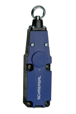
BNS 260-02Z-L
BNS 260-02Z-L
| Produkt-typebetegnelse: BNS 260-(1)(2)Z(3)-(4)-(5) |
| (1) | |
| 11 | 1 NO-kontakt / 1 NC-kontakt |
| 02 | 2 NC-kontakter |
| (2) | |
| uten | uten diagnostisk utgang |
| /01 | 1 NC-kontakter |
| (3) | |
| uten | uten lysdiode for brytertilstandsindikasjon |
| G | med lysdiode for brytertilstandsindikasjon |
| (4) | |
| uten | ferdigkoplet kabel |
| ST | med stikkontakt |
| (5) | |
| L | Dørhengsel på venstre side |
| R | høyrehengslet dør |
- ferdigkoplet kabel
- Plast bryterhus
- lite skog
- Skjult montering mulig
- 26 mm x 36 mm x 13 mm
- Lang levetid
- ingen mekanisk slitasje
- Ufølsom overfor tverrgående forskyvning
- Ufølsom overfor tilsmussing
Bestillingsinformasjon
| Produkt-typebetegnelse |
BNS 260-02Z-L |
| Artikkelnummer (bestillingsnummer) |
101184385 |
| EAN (European Article Number) |
4030661321851 |
| eCl@ss-nummer, versjon 12.0 |
27-27-44-01 |
| eCl@ss-nummer, versjon 11.0 |
27-27-24-02 |
| eCl@ss-nummer, versjon 9.0 |
27-27-24-02 |
| ETIM-nummer, versjon 7.0 |
EC002544 |
| ETIM-nummer, versjon 6.0 |
EC002544 |
Tillatelser - Standard
|
cULus |
Gobale egenskaper
| Standard |
BG-GS-ET-14 EN IEC 60947-5-3 |
| Kodenivå i henhold til ISO 14119 |
lav |
| Aktivt prinsipp |
Magnetisk drev |
| Installasjonsbetingelser (mekaniske) |
kvasi-i flukt |
| Kapslingsmateriale |
Plast, glassfiber forsterket termoplast |
| Bruttovekt |
55 g |
Gobale egenskaper - Karakteristikker
| Koding |
Ja |
| Antall åpnere |
2 |
| Antall sikkerhetskontakter |
2 |
Klassifisering
| Standard |
EN ISO 13849-1 |
| Mission time |
20 år |
Klassifisering - sikkerhetsutganger
| B10D Åpner (NC) |
25.000.000 bevegelser |
| B10D-verdi, NC-/NO-kontakt (NC/NO) |
25.000.000 bevegelser |
Mekaniske data
| Betjeningselement |
Magnet |
| Dørhengsel |
Venstre |
| Bevegelsesretning |
Frontalt til den aktive flaten |
Mechanical data - Switching distances
| Note (Switching distance Sn) |
Aksiell forkyvning Sikkerhetssensoren og aktuatoren tolererer en horisontal og vertikal feiljustering til hverandre. Den mulige feiljusteringen avhenger av avstanden til de aktive overflatene på sensoren og aktuatoren. Sensoren er aktiv i toleranseområdet. |
| Sikret bryteravstand "PÅ" |
5 mm |
| Sikret bryteravstand "AV" |
15 mm |
| Merk (bryterdistanse) |
All switching distances in accordance EN IEC 60947-5-3 |
Mechanical data - Connection technique
| Lengde for kabel |
1 m |
| Konnektor stikk |
kabel |
| Number of cable wires |
4 |
| Ledertverrsnitt |
0,25 mm2 |
| Ledertverrsnitt |
23 AWG |
| Materiale for kabelmantel |
PVC |
Mekaniske data - mål
| Lengde på sensor |
13 mm |
| Bredde på sensor |
26 mm |
| Høyde på sensor |
36 mm |
Omgivelsesbetingelser
| Tetthetsgrad |
IP67 |
| Arbeidstempratur |
-25 ... +70 °C |
| Lagrings- og transporttemparatur |
-25 ... +70 °C |
| Resistent mot vibrasjoner iht. EN 60068-2-6 |
10 … 55 Hz, Amplitude 1 mm |
| sjokkresitanse |
30 g / 11 ms |
Ambient conditions - Insulation values
| Isolasjonsspenning |
50 VAC |
| Nominell impulsmotstandsspenning |
0,8 kV |
Elektriske data
| Nødvendig nominell kortslutningsstrøm |
100 A |
| Brytespenning, maksimum |
75 VDC |
| Brytestrøm, maksimum |
0,4 A |
| Bryteeffekt, maksimum |
10 VA |
| Koblingselement |
2 NC-kontakter |
| Brytefrekvens, maksimum |
5 Hz |
inkludert ved levering
| inkludert ved levering |
Actuator must be ordered separately. |
Tilbehør
| Anbefaling (aktivator) |
BPS 260 |
| Recommended safety switchgear |
SRB-E-301ST SRB-E-201LC |
Note
| Note (General) |
Kontaktsymboler vist for verneinnretningen i lukket tilstand. Kontaktkonfigurasjonen for versjoner med eller uten lysdiode er identisk. |
Kablingseksempel
| Note (Wiring diagram) |
Kontakt S21-S22 og S11-S12 må integreres i sikkerhetskretsen |
Språk filter
Datablad
Operating Instructions and Declaration of Conformity (Short)
UL sertifikat
SISTEMA-VDMA Bibliotek/Library
Last ned den nyeste versjonen av Adobe Reader
Produktbilde (enkelt katalogbilde)
Dimensjonsriktig tegning grunnenhet
Diagram
Karakteristikk-kurve
Karakteristikk-kurve
Clipart

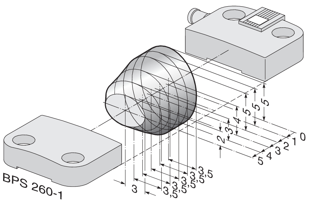
101184395 BPS 260-1
- Aktivator og sensor på et monteringsnivå

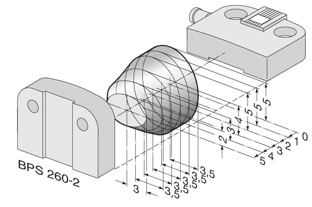
101184396 BPS 260-2
- Aktivator 90 ° festet til sensor
101184643 DISTANSEBRIKKE BNS 260
- for å montere den magnetiske sikkerhetssensoren og aktivatoren på ferromagnetisk materiale

103007672 SRB-E-301ST
- STOP 0 Funksjon
- 1 oder 2- kanalkontroll
- Startknapp / autostart
- 1 Hjelpekontakt
- 3 sikkerhetskontakter

103009970 SRB-E-201LC
- STOP 0 Funksjon
- 1 oder 2- kanalkontroll
- Startknapp / autostart
- 2 Sikkerhetsutganger 2 A
- 1 Signalutganger

103009973 SRB-E-204ST
- STOP 0 Funksjon
- Overvåking av 4 sensorer
- Startknapp / autostart
- 2 Sikkerhetsutganger
- 4 Signalutgang
Innholdsfortegnelse
- 1 About this document
- 1.1 Function
- 1.2 Target group of the operating instructions: authorised qualified personnel
- 1.3 Explanation of the symbols used
- 1.4 Appropriate use
- 1.5 General safety instructions
- 1.6 Warning about misuse
- 1.7 Exclusion of liability
- 2 Product description
- 2.1 Ordering code
- 2.2 Special versions
- 2.3 Purpose
- 2.4 Technical Data
- 3 Mounting
- 3.1 General mounting instructions
- 3.2 Dimensions
- 3.3 Axial misalignment
- 3.4 Adjustment
- 4 Electrical connection
- 4.1 General information for electrical connection
- 4.2 Contact Options
- 4.3 Connector accessories
- 5 Set-up and maintenance
- 6 Disassembly and disposal
- 6.1 Disassembly
- 6.2 Disposal
1 About this document
1.1 Function
This document provides all the information you need for the mounting, set-up and commissioning to ensure the safe operation and disassembly of the switchgear. The operating instructions enclosed with the device must always be kept in a legible condition and accessible.
1.2 Target group of the operating instructions: authorised qualified personnel
All operations described in the operating instructions manual must be carried out by trained specialist personnel, authorised by the plant operator only.
Please make sure that you have read and understood these operating instructions and that you know all applicable legislations regarding occupational safety and accident prevention prior to installation and putting the component into operation.
The machine builder must carefully select the harmonised standards to be complied with as well as other technical specifications for the selection, mounting and integration of the components.
The information contained in this operating instructions manual is provided without liability and is subject to technical modifications.
1.3 Explanation of the symbols used
- Information, hint, note: This symbol is used for identifying useful additional information.
- Caution: Failure to comply with this warning notice could lead to failures or malfunctions.
Warning: Failure to comply with this warning notice could lead to physical injury and/or damage to the machine.
1.4 Appropriate use
The Schmersal range of products is not intended for private consumers.
The products described in these operating instructions are developed to execute safety-related functions as part of an entire plant or machine. It is the responsibility of the manufacturer of a machine or plant to ensure the correct functionality of the entire machine or plant.
The safety switchgear must be exclusively used in accordance with the versions listed below or for the applications authorised by the manufacturer. Detailed information regarding the range of applications can be found in the chapter "Product description".
1.5 General safety instructions
The user must observe the safety instructions in this operating instructions manual, the country specific installation standards as well as all prevailing safety regulations and accident prevention rules.
- Further technical information can be found in the Schmersal catalogues or in the online catalogue on the Internet: products.schmersal.com.
1.6 Warning about misuse
- In case of improper use or manipulation of the safety switchgear, personal hazards or damages to machinery or plant components cannot be excluded. There are no residual risks, provided that the safety instructions as well as the instructions regarding mounting, commissioning, operation and maintenance are observed.
1.7 Exclusion of liability
We shall accept no liability for damages and malfunctions resulting from defective mounting or failure to comply with the operating instructions manual. The manufacturer shall accept no liability for damages resulting from the use of unauthorised spare parts or accessories.
For safety reasons, invasive work on the device as well as arbitrary repairs, conversions and modifications to the device are strictly forbidden, the manufacturer shall accept no liability for damages resulting from such invasive work, arbitrary repairs, conversions and/or modifications to the device.
2 Product description
2.1 Ordering code
| Product type description: BNS 260-(1)(2)Z(3)-(4)-(5) |
| (1) | |
| 11 | 1 NO contact/1 NC contact |
| 02 | 2 NC contact |
| (2) | |
| without | without diagnostic output |
| /01 | 1 NC contact |
| (3) | |
| without | without LED switching conditions display |
| G | with LED switching conditions display |
| (4) | |
| without | Pre-wired cable |
| ST | with connector |
| (5) | |
| L | Door hinge on left-hand side |
| R | Door hinge on right-hand side |
2.2 Special versions
For special versions, which are not listed in the ordering code, these specifications apply accordingly, provided that they correspond to the standard version.
2.3 Purpose
The safety sensor BNS 260 is designed to monitor the position of movable safetey guards in safety circuits to EN ISO 14119 and EN 60947-5-3. To actuate the safety sensors, only the BPS 260-1 or BPS 260-2 actuators can be used.
The safety switches are used for applications, in which the hazardous situation is terminated without delay when the safety guard is opened.
- The safety switchgears are classified according to EN ISO 14119 as type 4 interlocking devices.
Only the entire system consisting of the BNS 260 safety sensor and the BPS 260-1 or BPS 260-2 actuator and the safety-monitoring module (SRB) meets the requirements of the standard EN 60947-5-3.
- The user must evaluate and design the safety chain in accordance with the relevant standards and the required safety level.
- The entire concept of the control system, in which the safety component is integrated, must be validated to the relevant standards.
2.4 Technical Data
Tillatelser - Standard
|
cULus |
Gobale egenskaper
| Standard |
BG-GS-ET-14 EN IEC 60947-5-3 |
| Kodenivå i henhold til ISO 14119 |
lav |
| Aktivt prinsipp |
Magnetisk drev |
| Installasjonsbetingelser (mekaniske) |
kvasi-i flukt |
| Kapslingsmateriale |
Plast, glassfiber forsterket termoplast |
| Bruttovekt |
55 g |
Gobale egenskaper - Karakteristikker
| Koding |
Ja |
| Antall åpnere |
2 |
| Antall sikkerhetskontakter |
2 |
Klassifisering
| Standard |
EN ISO 13849-1 |
| Mission time |
20 år |
Klassifisering - sikkerhetsutganger
| B10D Åpner (NC) |
25.000.000 bevegelser |
| B10D-verdi, NC-/NO-kontakt (NC/NO) |
25.000.000 bevegelser |
Mekaniske data
| Betjeningselement |
Magnet |
| Dørhengsel |
Venstre |
| Bevegelsesretning |
Frontalt til den aktive flaten |
Mechanical data - Switching distances
| Note (Switching distance Sn) |
Aksiell forkyvning Sikkerhetssensoren og aktuatoren tolererer en horisontal og vertikal feiljustering til hverandre. Den mulige feiljusteringen avhenger av avstanden til de aktive overflatene på sensoren og aktuatoren. Sensoren er aktiv i toleranseområdet. |
| Sikret bryteravstand "PÅ" |
5 mm |
| Sikret bryteravstand "AV" |
15 mm |
| Merk (bryterdistanse) |
All switching distances in accordance EN IEC 60947-5-3 |
Mechanical data - Connection technique
| Lengde for kabel |
1 m |
| Konnektor stikk |
kabel |
| Number of cable wires |
4 |
| Ledertverrsnitt |
0,25 mm2 |
| Ledertverrsnitt |
23 AWG |
| Materiale for kabelmantel |
PVC |
Mekaniske data - mål
| Lengde på sensor |
13 mm |
| Bredde på sensor |
26 mm |
| Høyde på sensor |
36 mm |
Omgivelsesbetingelser
| Tetthetsgrad |
IP67 |
| Arbeidstempratur |
-25 ... +70 °C |
| Lagrings- og transporttemparatur |
-25 ... +70 °C |
| Resistent mot vibrasjoner iht. EN 60068-2-6 |
10 … 55 Hz, Amplitude 1 mm |
| sjokkresitanse |
30 g / 11 ms |
Ambient conditions - Insulation values
| Isolasjonsspenning |
50 VAC |
| Nominell impulsmotstandsspenning |
0,8 kV |
Elektriske data
| Nødvendig nominell kortslutningsstrøm |
100 A |
| Brytespenning, maksimum |
75 VDC |
| Brytestrøm, maksimum |
0,4 A |
| Bryteeffekt, maksimum |
10 VA |
| Koblingselement |
2 NC-kontakter |
| Brytefrekvens, maksimum |
5 Hz |
Kablingseksempel
| Note (Wiring diagram) |
Kontakt S21-S22 og S11-S12 må integreres i sikkerhetskretsen |
Note about the safety classification
For 2-channel use with suitable logic, can be used up to Cat. 4 / PL e.
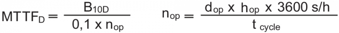
(Determined values can vary depending on the application-specific parameters hop, dop and tcycle as well as the load.)
If multiple safety components are wired in series, the Performance Level to EN ISO 13849-1 will be reduced due to the restricted error detection under certain circumstances.
UL notice
- For use in NFPA 79 Applications. Adapters providing field wiring means are available from the manufacturer. Refer to manufacturers information.
3 Mounting
3.1 General mounting instructions
- During fitting, the requirements of EN ISO 14119 must be observed.
- Fitting is only authorised in a de-energised condition
- Do not use the sensor and the actuator as a mechanical backstop
- Any mounting position, provided that the active surfaces are opposite
- Do not subject the safety sensor and actuator to extreme vibrations and shocks
To avoid any interference inherent to this kind of system and any reduction of the switching distances, please observe the following guidelines:
- Ensure the safety sensor is mounted on a flat surface
- Do not install the safety sensor and the actuator in strong magnetic fields
- If possible, do not mount the sensor and the actuator on ferromagnetic material. A non-magnetic spacer of at least 5 mm thick or the original spacer must be used. The use of non-magnetic fixing screws is recommended also.
- Keep away from metal chips
- The mounting distance between two sensors should always be at least 50 mm
- The actuator must be permanently fitted to the safety guards and protected against displacement by suitable measures (tamperproof screws, gluing, drilling of the screw heads).
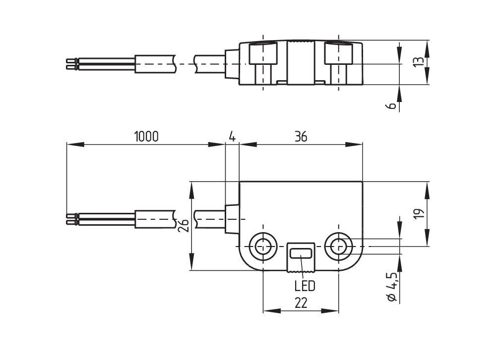
3.2 Dimensions
All measurements in mm.
Sensor with connector, right hinged door
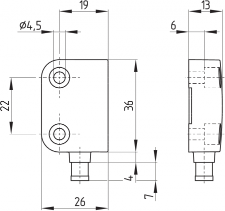
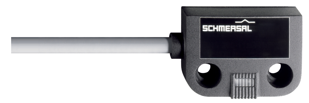
Safety sensor with cable, left hinged door

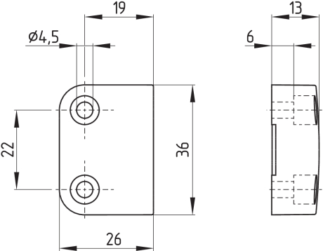
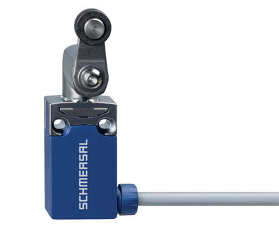
Actuator
3.3 Axial misalignment
A horizontal and vertical misalignment of the safety sensor and the actuator is tolerated. The possible misalignment depends on the distance of the active surfaces of the sensor and the actuator. The sensor remains active within the tolerance range.
The specified switching distances refer to opposedly mounted safety sensors and actuators.


| Assured switching distance: | sao | = | 5 mm 8 mm (ordering suffix -2750) |
| Assured switch-off distance: | sar | = | 15 mm 18 mm (ordering suffix -2750) |
3.4 Adjustment
- Recommended Adjustment
Align the safety sensor and actuator at a distance of 0.5 x sao.
Align the central markings of the safety sensor and the actuator with each other. The LED can only be used as rough setting tool. The correct functionality of both safety channels must be checked by means of the connected safety-monitoring module.
4 Electrical connection
4.1 General information for electrical connection
- The electrical connection may only be carried out by authorised personnel in a de-energised condition.
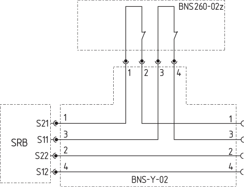
Connecting multiple safety sensors to one SRB safety-monitoring module is technically possible. To connect multiple safety sensors (check if authorised!), their NO contacts are wired in parallel and their NC contacts in series. The Protect-IE-11 or -02 or PROTECT-PE-11 (-AN) or -02 input expander module can be used to connect up to 4 safety sensors with NC/NC or NC/NO contacts.
Safety sensors equipped with LED's shall not be wired in series, except for the PROTECT-IE or PROTECT-PE input expander module. As a result of this, the luminosity of the LEDs would considerably decrease and the voltage could drop below the minimum input voltage of the downstream safety-monitoring module.
- Information for the selection of suitable safety-monitoring modules can be found in the Schmersal catalogues or in the online catalogue on the Internet: products.schmersal.com
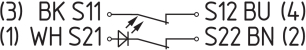
4.2 Contact Options
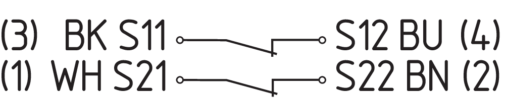
The safety sensors must be wired in accordance with the wire colours or the pin configuration.
The contact position shows the actuated sensor function when the safety guard is closed. For safety sensors with LED, the LED is illuminated when the safety guard is closed. The contact configurations of the versions with or without LED are identical.
| Safety contacts: | S21-S22 and S11-S12 or S13-S14 |
| Signalling contact: | S31-S32 |
The numbers between brackets indicate the PIN configuration of the versions with connector plug or connecting cable with connector; indication of the wire colours for the version with cable.
| BNS 260-02Z(G) | BNS 260-11Z(G) |
|---|---|
 | 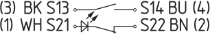 |
| BNS 260-02/01Z(G) | BNS 260-11/01Z(G) |
|---|---|
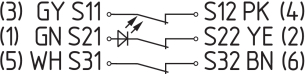 | 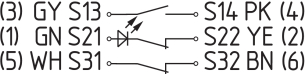 |
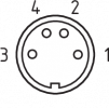
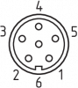
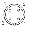
4.3 Connector accessories
| Connector plug or cable connector | ||
|---|---|---|
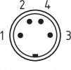 |  | 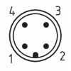 |
| M8, 4-pole, with screw terminal or snap fitting | 8 mm, 6-pole, with snap fitting | M12, 4-pole, screw connection with vibration safeguard |
Accessories: connecting cable with coupling
| M8, 4-pole, with screw terminal | 2 m | 5 m | 10 m | |||
|---|---|---|---|---|---|---|
 | 1 | BN | straight | 103011340 | 103007356 | - |
| 2 | WH | |||||
| 3 | BU | angled | 101210557 | 101210559 | - | |
| 4 | BK | |||||
| 8 mm, 6-pole, with snap fitting | 2 m | 5 m | 10 m | |||
|---|---|---|---|---|---|---|
 | 1 | GN | straight | 101206010 | 101206011 | 101206012 |
| 2 | YE | |||||
| 3 | GY | |||||
| 4 | PK | angled | 101206013 | 101206014 | 101206015 | |
| 5 | WH | |||||
| 6 | BN | |||||
| M12, 4-pole, with screw terminal | 2 m | 5 m | 10 m | |||
|---|---|---|---|---|---|---|
 | 1 | BN | Straight | 103010891 | 103010892 | 103010893 |
| 2 | WH | |||||
| 3 | BU | |||||
| 4 | BK | |||||
Accessory: Y-adapter BNS-Y-11
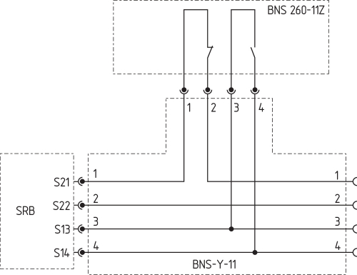
Accessory: Y-adapter BNS-Y-02
5 Set-up and maintenance
The safety function of the safety components must be tested. In the case of correct installation and adequate use, the safety switchgear features maintenance-free functionality. A regular visual inspection and functional test, including the following steps, is recommended:
- Check fixation of the safety switch and the actuator.
- Fitting and integrity of the cable connections.
- The system is free of dirt and soiling (in particular metal chips).
- Adequate measures must be taken to ensure protection against tampering either to prevent tampering of the safety guard, for instance by means of replacement actuators.
- Damaged or defective components must be replaced.
6 Disassembly and disposal
6.1 Disassembly
The safety switchgear must be disassembled in a de-energised condition only.
6.2 Disposal
- The safety switchgear must be disposed of in an appropriate manner in accordance with the national prescriptions and legislations.
| EU Declaration of Conformity |  |
| Original | K.A. Schmersal GmbH & Co. KG Möddinghofe 30 42279 Wuppertal Germany Internet: www.schmersal.com |
| Declaration: | We hereby certify that the hereafter described components both in their basic design and construction conform to the applicable European Directives. |
| Name of the component: | BNS 260 |
| Type: | See ordering code |
| Description of the component: | Coded safety-sensor with magnetic operating principle in combination with the SRB(-E) / PROTECT-SELECT / PSC1 safety-monitoring modules from Schmersal or an equivalent safety-oriented control system fulfilling the requirements of the EN 60947-5-3. |
| Relevant Directives: | Machinery Directive | 2006/42/EC |
| RoHS-Directive | 2011/65/EU |
| Applied standards: | EN 60947-5-3:2013 EN ISO 14119:2013 |
| Person authorised for the compilation of the technical documentation: | Oliver Wacker Möddinghofe 30 42279 Wuppertal |
| Place and date of issue: | Wuppertal, January 28, 2022 |
 |
| Authorised signature Philip Schmersal Managing Director |
| UK Declaration of Conformity | |
| Company: | K.A. Schmersal GmbH & Co. KG Möddinghofe 30 42279 Wuppertal Germany Internet: www.schmersal.com |
| Declaration: | We hereby, under sole responsibility, certify that the hereafter described components both in their basic design and construction conform to the relevant statutory requirements, regulations and designated standards of the United Kingdom. |
| Name of the component: | BNS 260 |
| Type: | See ordering code |
| Description of the component: | Coded safety-sensor with magnetic operating principle in combination with the SRB(-E) / PROTECT-SELECT / PSC1 safety-monitoring modules from Schmersal or an equivalent safety-oriented control system fulfilling the requirements of the EN 60947-5-3. |
| Relevant legislation: | Supply of Machinery (Safety) Regulations | 2008 |
| The Restriction of the Use of Certain Hazardous Substances in Electrical and Electronic Equipment Regulations | 2012 |
| Designated standards: | EN 60947-5-3:2013 EN ISO 14119:2013 |
| UK-Importer / Person authorised for the compilation of the technical documentation: | Schmersal UK Ltd. Paul Kenney Unit 1, Sparrowhawk Close Enigma Business Park Malvern, Worcestershire, WR14 1GL |
| Place and date of issue: | Wuppertal, June 17, 2022 |
|
| Authorised signature Philip Schmersal Managing Director |
Schmersal Nordiska AB, F O Petersons gata 28, S-421 31 Västra Frölunda
Data og verdier er kontrollert omhyggelig. Bilder kan avvike fra originalen. Ytterligere tekniske data finner du i manualen. Tekniske modifiseringer og feil kan forkomme.
Generert til 09.09.2025, 05:17
Nylig sett

TS 015-11E EINSATZ
PS116-Z11-LR500-H200

PS116-T02H-LR200-S200
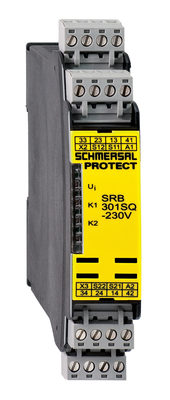
SRB301SQ 230V