AZM400Z-ST-I2-1P2P-BOW
AZM400Z-ST-I2-1P2P-BOW
| Product type description: AZM400Z-(1)-(2)-(3)-(4)-(5) |
| (1) | |
| ST | 1 Connector plug M12, 8-pin |
| ST2 | 2 Connector plug M12, 8-pin / 5-pin |
| (2) | |
| without | Standard coding |
| I1 | Individual coding |
| I2 | Individual coding, multiple teaching |
| (3) | |
| 1P2P | 1 serial diagnostic output and 2 p-type safety outputs (only for ST) |
| 2P2P | 2 serial diagnostic output and 2 p-type safety outputs (only for ST2) |
| (4) | |
| without | Manual release |
| T | Emergency exit |
| BOW | With securing holes for Bowden cable assembly |
| (5) | |
| without | without electronic manual release (Only for ST) |
| E | with electronic manual release (Only for ST2) |
- Repeated individual coding with RFID technology
- Universal coding with RFID technology
- Connector M12, 8-pole
- Guard locking monitored
- 1 Diagnostic output
- With securing holes for Bowden cable assembly
- Bistable, motor-driven system
- Clamping force 10.000
- Release possible against lateral forces up to 300 N
- PL e / cat. 4 / SIL 3 for interlocking and guard locking function
- Two-channel input signal of the guard locking function
- Operation on P/P- and P/N-switching outputs
- High tolerance to door misalignment
Ordering data
| Product type description |
AZM400Z-ST-I2-1P2P-BOW |
| Article number (order number) |
103015315 |
| EAN (European Article Number) |
4030661503967 |
| eCl@ss number, version 12.0 |
27-27-26-03 |
| eCl@ss number, version 11.0 |
27-27-26-03 |
| eCl@ss number, version 9.0 |
27-27-26-03 |
| ETIM number, version 7.0 |
EC002593 |
| ETIM number, version 6.0 |
EC002593 |
Approvals - Standards
| Certificates |
TÜV cULus FCC IC UKCA ANATEL |
General data
| Standards |
EN ISO 13849-1 EN ISO 14119 EN IEC 60947-5-3 EN IEC 61508 |
| Coding |
Individual coding, multiple teaching |
| Coding level according to EN ISO 14119 |
High |
| Working principle |
Magnetic field RFID |
| Frequency band RFID |
125 kHz |
| Transmitter output RFID, maximum |
-6 dB/m |
| Housing material |
Light alloy die-casting |
| Reaction time, switching off safety outputs via actuator, maximum |
100 ms |
| Gross weight |
856 g |
General data - Features
| Solenoid interlock monitored |
Yes |
| Short circuit detection |
Yes |
| Cross-circuit detection |
Yes |
| Securing holes for Bowden cable assembly |
Yes |
| Safety functions |
Yes |
| Integral system diagnostics, status |
Yes |
| Number of diagnostic signals |
1 |
| Number of safety contacts |
2 |
| Safety classification |
| Vorschriften |
EN ISO 13849-1 EN IEC 61508 |
Safety classification - Interlocking function
| Performance Level, up to |
e |
| Category |
4 |
| PFH value |
1.00 x 10⁻⁹ /h |
| PFD value |
9.00 x 10⁻⁵ |
| Safety Integrity Level (SIL), suitable for applications in |
3 |
| Mission time |
20 Year(s) |
Safety classification - Guard locking function
| Performance Level, up to |
e |
| Category |
4 |
| PFH value |
1.80 x 10⁻⁹ /h |
| PFD value |
1.60 x 10⁻⁴ |
| Safety Integrity Level (SIL), suitable for applications in |
3 |
| Mission time |
20 Year(s) |
Mechanical data
| Interlocking principle |
bistable |
| Mechanical life, minimum |
1,000,000 Operations |
| Note (Mechanical life) |
Which have a lateral force Ftrans = 100 N: 100.000 operations |
| Allowed distance interlock to actuator, minimum |
1 mm |
| Allowed distance interlock to actuator, maximum |
7 mm |
| Angular misalignment between solenoid interlock and actuator, maximum |
2 ° |
| Minimum distance devices |
30 mm |
| Holding force FZh in accordance with EN ISO 14119 |
10,000 N |
| Holding force Fmax, maximum |
13,000 N |
| Lateral force at bolt return, maximal (against locked door) |
300 N |
| Note (Lateral force at bolt return) |
Does not apply to emergency exit, Bowden cable and manual release |
| Type of the fixing screws |
2x M6 |
| Note (Type of the fixing screws) |
Property class min. 10.9 |
| Tightening torque of the screw |
8 Nm |
| Tightening torque of the fixing screws Bowden cable |
1.2 Nm |
Mechanical data - Connection technique
| Termination |
Connector M12, 8-pole, A-coded |
Mechanical data - Dimensions
| Length of sensor |
46.7 mm |
| Width of sensor |
77.8 mm |
| Height of sensor |
156.7 mm |
Ambient conditions
| Degree of protection |
IP66 IP67 |
| Note |
Protection class remains with correctly installed bowden cable release |
| Ambient temperature |
-20 ... +55 °C |
| Storage and transport temperature |
-40 ... +85 °C |
| Relative humidity, maximum |
93 % |
| Note (Relative humidity) |
non-condensing non-icing |
| Resistance to vibrations |
10 … 150 Hz, amplitude 0.35 mm |
| Restistance to shock |
30 g / 11 ms |
| Protection class |
III |
| Permissible installation altitude above sea level, maximum |
2,000 m |
Ambient conditions - Insulation values
| Rated insulation voltage Ui |
32 VDC |
| Rated impulse withstand voltage Uimp |
0.8 kV |
| Overvoltage category |
III |
| Degree of pollution |
3 |
Electrical data
| Operating voltage |
24 VDC -15 % / +10 % (stabilised PELV power supply) |
| No-load supply current I0, typical |
100 mA |
| Operating current while bolt movement, peak |
600 mA / 100 ms |
| Rated operating voltage |
24 VDC |
| Required rated short-circuit current |
100 A |
| External wire and device fuse rating |
2 A gG |
| Time to readiness, maximum |
1,500 ms |
| Switching frequency, maximum |
0.3 Hz |
| Open / close cycle (motor), minimum |
3 |
| Minimal average cycle time (with continuous operation) |
20 s |
| Utilisation category DC-12 |
24 VDC / 0.05 A |
| Electrical fuse rating, maximum |
2 A |
Electrical data - Control inputs Guard locking function
| Designation, Control inputs |
E1 und E2 (p-schaltend), E3 (n-schaltend) |
| Switching thresholds of the control inputs |
−3 V … 5 V (Low) 15 V … 30 V (High) |
| Classification ZVEI CB24I, Sink |
C0 |
| Classification ZVEI CB24I, Source |
C1 C2 C3 |
| Current consumption at 24V, minimum |
5 mA |
| Current consumption at 24V, maximum |
10 mA |
| Allowable discrepancy time (input), maximum |
10 s |
| Test pulse interval, maximum |
40 ms |
| Test pulse duration, maximum |
5 ms |
| Permissible residual drive current |
1.5 mA |
Electrical data - Safety digital outputs
| Designation, Safety outputs |
Y1 and Y2 |
| Design of control elements |
short-circuit proof, p-type |
| Voltage drop Ud, maximum |
2 V |
| Leakage current Ir, maximum |
0.5 mA |
| Voltage, Utilisation category DC-12 |
24 VDC |
| Current, Utilisation category DC-12 |
0.25 A |
| Voltage, Utilisation category DC-13 |
24 VDC |
| Current, Utilisation category DC-13 |
0.25 A |
| Test pulse interval, typical |
1000 ms |
| Test pulse duration, maximum |
0.5 ms |
| Classification ZVEI CB24I, Source |
C2 |
| Classification ZVEI CB24I, Sink |
C1 C2 |
Electrical data - Diagnostic outputs
| Designation, Diagnostic outputs |
OUT |
| Design of control elements |
short-circuit proof, p-type |
| Voltage drop Ud, maximum |
2 V |
| Voltage, Utilisation category DC-12 |
24 VDC |
| Current, Utilisation category DC-12 |
0.05 A |
| Voltage, Utilisation category DC-13 |
24 VDC |
| Current, Utilisation category DC-13 |
0.05 A |
| Note |
The diagnostic output are not safety relevant outputs! |
Status indication
| Note (LED switching conditions display) |
Operating condition: LED green Error / functional defect: LED red Supply voltage UB: LED green |
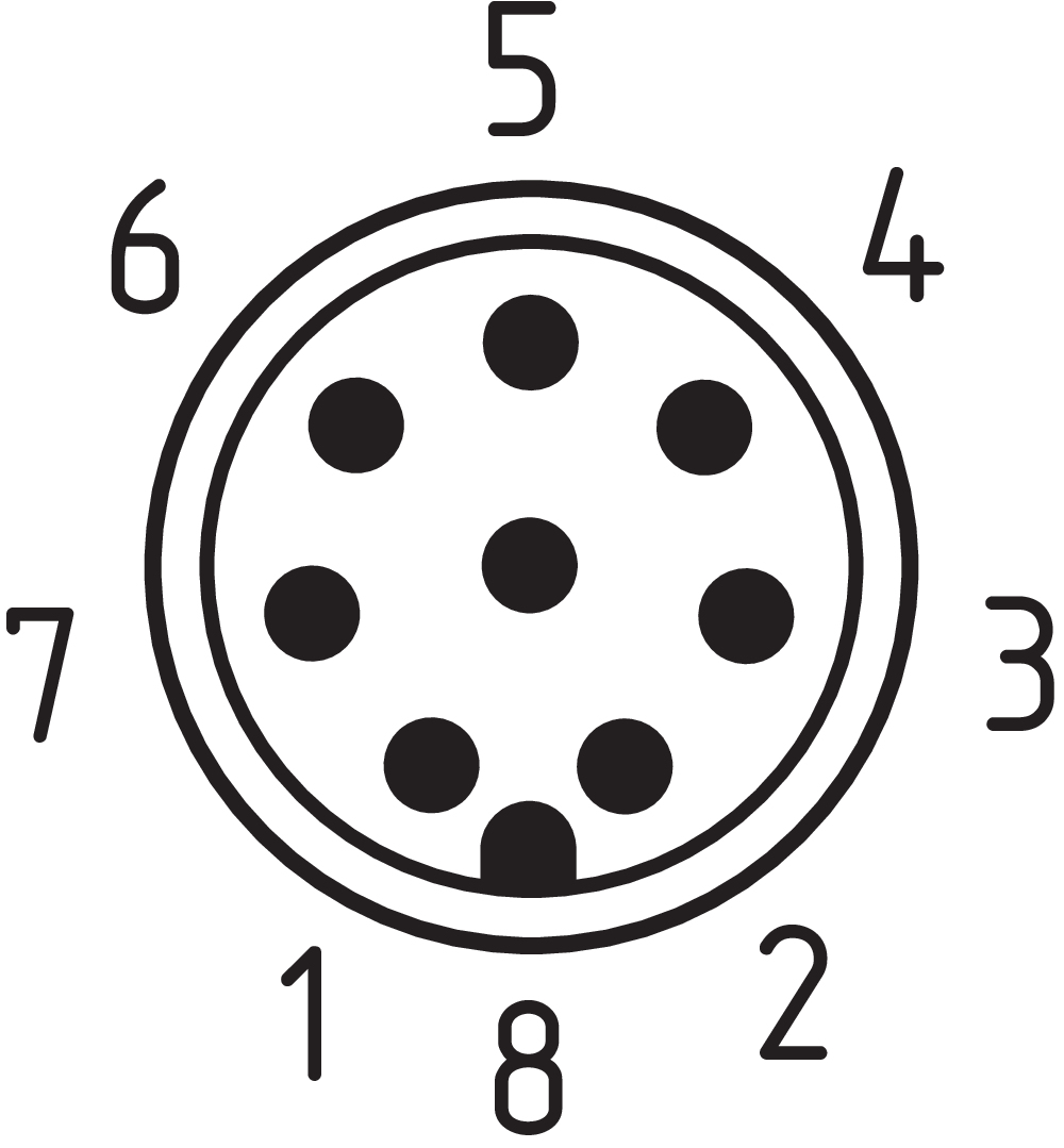
Pin assignment
| PIN 1 |
A1 Supply voltage UB |
| PIN 2 |
E1 Control input 1 |
| PIN 3 |
A2 GND |
| PIN 4 |
Y1 Safety output 1 |
| PIN 5 |
OUT Diagnostic output |
| PIN 6 |
E3 Control input 3 |
| PIN 7 |
Y2 Safety output 2 |
| PIN 8 |
E2 Control input 2 |
Scope of delivery
| Scope of delivery |
The actuator and the Bowden cable are not included in delivery. Note: Versions AZM400Z-...-BOW may only be used in connection with Bowden cable release ACC-AZM400-BOW-.M-.M, which is available as an accessory. Use without the Bowden cable release fitted is not permissible. |
Accessory
| Recommendation (actuator) |
AZM400-B1 |
Language filter
Datasheet
Operating instructions and Declaration of conformity
ANATEL certification
TÜV certification
UL Certificate
FCC-Zertifikat
IC-Zertifikat
UKCA certificate
Brochure
SISTEMA-VDMA library
Download the latest version of Adobe Reader
Product picture (catalogue individual photo)
Dimensional drawing basic component
Dimensional drawing basic component
Dimensional drawing miscellaneous
Contact arrangement
Video ID: azm400-01
Single device connection (Youtube)

Single device connection (Vimeo)
Video ID: azm400-02
Tolerance to misalignment (Youtube)
Tolerance to misalignment (Vimeo)
Video ID: azm400-03
Opening in case of uptighted doors (Youtube)
Opening in case of uptighted doors (Vimeo)
Video ID: azm400-04
Safety function in case of voltage breakdown (Youtube)
Safety function in case of voltage breakdown (Vimeo)
Video ID: azm400-05
Block driver (Youtube)
Block driver (Vimeo)
Video ID: azm400-06
Cross-fault with controlled shut-down process (Youtube)
Cross-fault with controlled shut-down process (Vimeo)
Video ID: azm400-08
Replacement actuator AZM...-I (Youtube)
Replacement actuator AZM...-I (Vimeo)
Video ID: azm400-09
Teaching of a replacement actuator AZM...-I2 (Youtube)
Teaching of a replacement actuator AZM...-I2 (Vimeo)
103015308 ACC-AZM400-BOW-4M-6M
- Remote release via a wire rope
- Can be used as emergency exit or emergency release
- Length of sheathed steel core: 4 m
- total length: 6
103038783 ACC-AZM400-BOW-6M-8M
- Remote release via a wire rope
- Can be used as emergency exit or emergency release
- Length of sheathed steel core: 6 m
- Length: 8 m

103009179 MS-AZM400
- Mounting kit consisting of two mounting plates, four M6 countersunk screws and four M6 special nuts
- Simple fitting, especially on 40 mm profiles
- Mounting plates with elongated holes for optimal alignment
103015742 SZ400
- Suitable for mounting inside and outside of the hazardous area
- Suitable for hinged and sliding guards
- To prevent inadvertent closing, e.g. during maintenance
- For complex plant
- Prevents actuation of the switch
- Lockout tag with 6 circular holes

103007672 SRB-E-301ST
- Plug-in screw terminals with coding
- STOP 0 Function
- 1 oder 2-channel control
- Start button / Auto-start
- 1 Auxiliary contact
- 3 safety contacts

103009970 SRB-E-201LC
- Plug-in screw terminals with coding
- STOP 0 Function
- 1 oder 2-channel control
- Start button / Auto-start
- 2 Safety outputs 2 A
- 1 Signalling output

103009973 SRB-E-204ST
- Plug-in screw terminals with coding
- STOP 0 Function
- Monitoring of 4 sensors
- Start button / Auto-start
- 2 Safety outputs
- 4 Signalling outputs

103003508 AZM400-B1
- Actuator for solenoid interlock AZM400
103001389 A-K8P-M12-S-G-10M-BK-1-X-A-4-69-VA
- 10 m
- Pre-wired cable
- 8-pole
103007359 A-K8P-M12-S-G-10M-BK-2-X-A-4-69
- 10 m
- Pre-wired cable
- 8-pole
103011413 A-K8P-M12-S-G-10M-GY-1-X-A-4
- 10 m
- Pre-wired cable
- 8-pole
103011414 A-K8P-M12-S-G-15M-BK-2-X-A-4-69
- 15
- Pre-wired cable
- 8-pole
103011415 A-K8P-M12-S-G-2,5M-BK-2-X-A-4-69
- 2.5 m
- Pre-wired cable
- 8-pole
103011411 A-K8P-M12-S-G-2,5M-GY-1-X-A-4
- 2.5 m
- Pre-wired cable
- 8-pole
101210560 A-K8P-M12-S-G-5M-BK-1-X-A-4-69-VA
- 5 m
- Pre-wired cable
- 8-pole
103007358 A-K8P-M12-S-G-5M-BK-2-X-A-4-69
- 5 m
- Pre-wired cable
- 8-pole
103011412 A-K8P-M12-S-G-5M-GY-1-X-A-4
- 5.0
- Pre-wired cable
- 8-pole
101210561 A-K8P-M12-S-W-5M-BK-1-X-A-4-69-VA
- 5 m
- angled
- Pre-wired cable
- 8-pole
103011416 A-K8P-M12-S-W-5M-GY-1-X-A-4
- 5 m
- Pre-wired cable
- 8-pole
103011787 A-K8P-M12-S-G-15M-GY-1-X-A-4
- 15
- Pre-wired cable
- 8-pole
103014823 A-K8P-M12-S-G-15M-BK-1-X-A-4-69-VA
- 15
- Pre-wired cable
- 8-pole
Table of Contents
- 1 About this document
- 1.1 Function
- 1.2 Target group of the operating instructions: authorised qualified personnel
- 1.3 Explanation of the symbols used
- 1.4 Appropriate use
- 1.5 General safety instructions
- 1.6 Warning about misuse
- 1.7 Exclusion of liability
- 2 Product description
- 2.1 Ordering code
- 2.2 Special versions
- 2.3 Purpose
- 2.4 Technical Data
- 3 Mounting
- 3.1 General mounting instructions
- 3.2 Manual release
- 3.3 Electrical manual release - E (for -ST2)
- 3.4 Emergency exit -T
- 3.5 Assembly with mounting set
- 3.6 Dimensions
- 3.7 Actuator and accessories
- 4 Electrical connection
- 4.1 General information for electrical connection
- 4.2 Control options in the normal operating mode
- 4.3 Requirements for the connected safety-monitoring module
- 4.4 Wiring configuration and connector accessories
- 4.5 Wiring examples
- 5 Actuator teaching / actuator detection
- 6 Active principle and diagnostic functions
- 6.1 Mode of operation of the safety outputs
- 6.2 Diagnostic-LEDs
- 6.3 Diagnostic outputs
- 6.4 Diagnostic information
- 7 Set-up and maintenance
- 7.1 Functional testing
- 7.2 Maintenance
- 8 Disassembly and disposal
- 8.1 Disassembly
- 8.2 Disposal
1 About this document
1.1 Function
This document provides all the information you need for the mounting, set-up and commissioning to ensure the safe operation and disassembly of the switchgear. The operating instructions enclosed with the device must always be kept in a legible condition and accessible.
1.2 Target group of the operating instructions: authorised qualified personnel
All operations described in the operating instructions manual must be carried out by trained specialist personnel, authorised by the plant operator only.
Please make sure that you have read and understood these operating instructions and that you know all applicable legislations regarding occupational safety and accident prevention prior to installation and putting the component into operation.
The machine builder must carefully select the harmonised standards to be complied with as well as other technical specifications for the selection, mounting and integration of the components.
1.3 Explanation of the symbols used
- Information, hint, note: This symbol is used for identifying useful additional information.
- Caution: Failure to comply with this warning notice could lead to failures or malfunctions.
Warning: Failure to comply with this warning notice could lead to physical injury and/or damage to the machine.
1.4 Appropriate use
The Schmersal range of products is not intended for private consumers.
The products described in these operating instructions are developed to execute safety-related functions as part of an entire plant or machine. It is the responsibility of the manufacturer of a machine or plant to ensure the correct functionality of the entire machine or plant.
The safety switchgear must be exclusively used in accordance with the versions listed below or for the applications authorised by the manufacturer. Detailed information regarding the range of applications can be found in the chapter "Product description".
1.5 General safety instructions
The user must observe the safety instructions in this operating instructions manual, the country specific installation standards as well as all prevailing safety regulations and accident prevention rules.
- Further technical information can be found in the Schmersal catalogues or in the online catalogue on the Internet: products.schmersal.com.
The information contained in this operating instructions manual is provided without liability and is subject to technical modifications.
There are no residual risks, provided that the safety instructions as well as the instructions regarding mounting, commissioning, operation and maintenance are observed.
1.6 Warning about misuse
- In case of inadequate or improper use or manipulations of the component, personal hazards or damage to machinery or plant components cannot be excluded.
1.7 Exclusion of liability
We shall accept no liability for damages and malfunctions resulting from defective mounting or failure to comply with the operating instructions manual. The manufacturer shall accept no liability for damages resulting from the use of unauthorised spare parts or accessories.
For safety reasons, invasive work on the device as well as arbitrary repairs, conversions and modifications to the device are strictly forbidden, the manufacturer shall accept no liability for damages resulting from such invasive work, arbitrary repairs, conversions and/or modifications to the device.
2 Product description
2.1 Ordering code
| Product type description: AZM400Z-(1)-(2)-(3)-(4)-(5) |
| (1) | |
| ST | 1 Connector plug M12, 8-pin |
| ST2 | 2 Connector plug M12, 8-pin / 5-pin |
| (2) | |
| without | Standard coding |
| I1 | Individual coding |
| I2 | Individual coding, multiple teaching |
| (3) | |
| 1P2P | 1 serial diagnostic output and 2 p-type safety outputs (only for ST) |
| 2P2P | 2 serial diagnostic output and 2 p-type safety outputs (only for ST2) |
| (4) | |
| without | Manual release |
| T | Emergency exit |
| BOW | With securing holes for Bowden cable assembly |
| (5) | |
| without | without electronic manual release (Only for ST) |
| E | with electronic manual release (Only for ST2) |
| Actuator | AZM400-B1 |
- Versions AZM400Z-...-BOW may only be used in connection with Bowden cable release ACC-AZM400-BOW-.M-.M, which is available as accessory. Use without the Bowden cable release fitted is not permissible. Observe the additional notes in the operating instructions of the Bowden cable release.
2.2 Special versions
For special versions, which are not listed in the ordering code, these specifications apply accordingly, provided that they correspond to the standard version.
2.3 Purpose
The non-contact, electronic safety switchgear is designed for application in safety circuits and is used for monitoring the position and locking of movable safety guards.
- The safety switchgears are classified according to EN ISO 14119 as type 4 interlocking devices. Designs with individual coding are classified as highly coded.
The first of the two safety functions is the safe shut-down of both safety outputs when unlocking or opening the guard system and making sure that the switched-off position is maintained when the guard system is open or unlocked (locking function). The second safety function (interlocking function) is the safe interlocking of a guard system which was locked only once. The locking of the guard system may only be switched off when there is no fault and a valid signal to unlock is present.
When the guard system is closed and there is a valid two-channel control signal applied by the user or through the controller, the locking bolt of the AZM400 can be driven out. As soon as the locking bolt have reached sufficient depth in the locking hole the guard system is considered to be safely locked.
The AZM400 solenoid interlock is a bi-stable system, which means the interlock remains in the last position if power is lost.
- The user must evaluate and design the safety chain in accordance with the relevant standards and the required safety level. If multiple safety sensors are involved in the same safety function, the PFH values of the individual components must be added.
- The entire concept of the control system, in which the safety component is integrated, must be validated to the relevant standards.
2.4 Technical Data
Approvals - Standards
| Certificates |
TÜV cULus FCC IC UKCA ANATEL |
General data
| Standards |
EN ISO 13849-1 EN ISO 14119 EN IEC 60947-5-3 EN IEC 61508 |
| Coding |
Individual coding, multiple teaching |
| Coding level according to EN ISO 14119 |
High |
| Working principle |
Magnetic field RFID |
| Frequency band RFID |
125 kHz |
| Transmitter output RFID, maximum |
-6 dB/m |
| Housing material |
Light alloy die-casting |
| Reaction time, switching off safety outputs via actuator, maximum |
100 ms |
| Gross weight |
856 g |
General data - Features
| Solenoid interlock monitored |
Yes |
| Short circuit detection |
Yes |
| Cross-circuit detection |
Yes |
| Securing holes for Bowden cable assembly |
Yes |
| Safety functions |
Yes |
| Integral system diagnostics, status |
Yes |
| Number of diagnostic signals |
1 |
| Number of safety contacts |
2 |
| Safety classification |
| Vorschriften |
EN ISO 13849-1 EN IEC 61508 |
Safety classification - Interlocking function
| Performance Level, up to |
e |
| Category |
4 |
| PFH value |
1.00 x 10⁻⁹ /h |
| PFD value |
9.00 x 10⁻⁵ |
| Safety Integrity Level (SIL), suitable for applications in |
3 |
| Mission time |
20 Year(s) |
Safety classification - Guard locking function
| Performance Level, up to |
e |
| Category |
4 |
| PFH value |
1.80 x 10⁻⁹ /h |
| PFD value |
1.60 x 10⁻⁴ |
| Safety Integrity Level (SIL), suitable for applications in |
3 |
| Mission time |
20 Year(s) |
Mechanical data
| Interlocking principle |
bistable |
| Mechanical life, minimum |
1,000,000 Operations |
| Note (Mechanical life) |
Which have a lateral force Ftrans = 100 N: 100.000 operations |
| Allowed distance interlock to actuator, minimum |
1 mm |
| Allowed distance interlock to actuator, maximum |
7 mm |
| Angular misalignment between solenoid interlock and actuator, maximum |
2 ° |
| Minimum distance devices |
30 mm |
| Holding force FZh in accordance with EN ISO 14119 |
10,000 N |
| Holding force Fmax, maximum |
13,000 N |
| Lateral force at bolt return, maximal (against locked door) |
300 N |
| Note (Lateral force at bolt return) |
Does not apply to emergency exit, Bowden cable and manual release |
| Type of the fixing screws |
2x M6 |
| Note (Type of the fixing screws) |
Property class min. 10.9 |
| Tightening torque of the screw |
8 Nm |
| Tightening torque of the fixing screws Bowden cable |
1.2 Nm |
Mechanical data - Connection technique
| Termination |
Connector M12, 8-pole, A-coded |
Mechanical data - Dimensions
| Length of sensor |
46.7 mm |
| Width of sensor |
77.8 mm |
| Height of sensor |
156.7 mm |
Ambient conditions
| Degree of protection |
IP66 IP67 |
| Note |
Protection class remains with correctly installed bowden cable release |
| Ambient temperature |
-20 ... +55 °C |
| Storage and transport temperature |
-40 ... +85 °C |
| Relative humidity, maximum |
93 % |
| Note (Relative humidity) |
non-condensing non-icing |
| Resistance to vibrations |
10 … 150 Hz, amplitude 0.35 mm |
| Restistance to shock |
30 g / 11 ms |
| Protection class |
III |
| Permissible installation altitude above sea level, maximum |
2,000 m |
Ambient conditions - Insulation values
| Rated insulation voltage Ui |
32 VDC |
| Rated impulse withstand voltage Uimp |
0.8 kV |
| Overvoltage category |
III |
| Degree of pollution |
3 |
Electrical data
| Operating voltage |
24 VDC -15 % / +10 % (stabilised PELV power supply) |
| No-load supply current I0, typical |
100 mA |
| Operating current while bolt movement, peak |
600 mA / 100 ms |
| Rated operating voltage |
24 VDC |
| Required rated short-circuit current |
100 A |
| External wire and device fuse rating |
2 A gG |
| Time to readiness, maximum |
1,500 ms |
| Switching frequency, maximum |
0.3 Hz |
| Open / close cycle (motor), minimum |
3 |
| Minimal average cycle time (with continuous operation) |
20 s |
| Utilisation category DC-12 |
24 VDC / 0.05 A |
| Electrical fuse rating, maximum |
2 A |
Electrical data - Control inputs Guard locking function
| Designation, Control inputs |
E1 und E2 (p-schaltend), E3 (n-schaltend) |
| Switching thresholds of the control inputs |
−3 V … 5 V (Low) 15 V … 30 V (High) |
| Classification ZVEI CB24I, Sink |
C0 |
| Classification ZVEI CB24I, Source |
C1 C2 C3 |
| Current consumption at 24V, minimum |
5 mA |
| Current consumption at 24V, maximum |
10 mA |
| Allowable discrepancy time (input), maximum |
10 s |
| Test pulse interval, maximum |
40 ms |
| Test pulse duration, maximum |
5 ms |
| Permissible residual drive current |
1.5 mA |
Electrical data - Safety digital outputs
| Designation, Safety outputs |
Y1 and Y2 |
| Design of control elements |
short-circuit proof, p-type |
| Voltage drop Ud, maximum |
2 V |
| Leakage current Ir, maximum |
0.5 mA |
| Voltage, Utilisation category DC-12 |
24 VDC |
| Current, Utilisation category DC-12 |
0.25 A |
| Voltage, Utilisation category DC-13 |
24 VDC |
| Current, Utilisation category DC-13 |
0.25 A |
| Test pulse interval, typical |
1000 ms |
| Test pulse duration, maximum |
0.5 ms |
| Classification ZVEI CB24I, Source |
C2 |
| Classification ZVEI CB24I, Sink |
C1 C2 |
Electrical data - Diagnostic outputs
| Designation, Diagnostic outputs |
OUT |
| Design of control elements |
short-circuit proof, p-type |
| Voltage drop Ud, maximum |
2 V |
| Voltage, Utilisation category DC-12 |
24 VDC |
| Current, Utilisation category DC-12 |
0.05 A |
| Voltage, Utilisation category DC-13 |
24 VDC |
| Current, Utilisation category DC-13 |
0.05 A |
| Note |
The diagnostic output are not safety relevant outputs! |
Status indication
| Note (LED switching conditions display) |
Operating condition: LED green Error / functional defect: LED red Supply voltage UB: LED green |
Pin assignment
| PIN 1 |
A1 Supply voltage UB |
| PIN 2 |
E1 Control input 1 |
| PIN 3 |
A2 GND |
| PIN 4 |
Y1 Safety output 1 |
| PIN 5 |
OUT Diagnostic output |
| PIN 6 |
E3 Control input 3 |
| PIN 7 |
Y2 Safety output 2 |
| PIN 8 |
E2 Control input 2 |
UL notice
For use in NFPA 79 Applications only.
Use Limited Voltage/Current power supply only.
Adapters providing field wiring means are available from the manufacturer. Refer to manufacurers information.
This device shall be powered with the use of a Listed (CYJV) cable/connector assembly rated 24Vdc, 0.6A minimum.
FCC/IC - Note
This device complies with Part 15 of the FCC Rules and contains licence-exempt transmitter/receivers that are compliant with ISED (Innovation, Science and Economic Development) Canada licence-exempt RSS standard(s).
Operation is subject to the following two conditions:
(1) This device may not cause harmful interference signals, and
(2) This device must be able to tolerate interference signals. These also include interference signals that could cause the device to function improperly.
This device complies with the nerve stimulation limits (ISED SPR-002) when operated at a minimum distance of 100 mm. Changes or modifications not expressly approved by K.A. Schmersal GmbH & Co. KG could void the user's authority to operate the equipment.
The licence-free transmitter/receiver contained in this device satisfies the requirements of the "Radio Standards Specification" of the Innovation, Science and Economic Development Canada (ISED) authority that apply to licence-free radio equipment. Operation is permissible under the following two conditions:
(1) The device must not create disturbances.
(2) The device must tolerate received radio frequency interference, even if this could impair its functionality.
This device complies with the nerve stimulation limits (ISED CNR-102) when operated at a minimum distance of 100 mm.
In the event of changes or modifications that have not been expressly approved by K.A. Schmersal GmbH & Co. KG, the user's authorisation to use the device may become ineffective.
| 20941-22-14519 | Este equipamento nao tem direito àprotecao contra interferência prejudicial e nao pode causar interferencia em sistemas devidamente autorizados. Para maiores informacores consultar: www.gov.br/anatel |
3 Mounting
3.1 General mounting instructions
- Please observe the remarks of the standards EN ISO 12100, EN ISO 14119 and EN ISO 14120.
Any position is possible.
- The accumulation of fine-grained dirt in the bolt area must be avoided.
In such a case it is therefore not advised to have vertical mounting, where the bolt goes upwards from below.
For the correct fixing of the solenoid interlock, the device is provided with two mounting holes for M6-screws.
- The M6 screws should have at least the strength class 10.9. The tightening torque of the M6 screws is 8 Nm.
- The actuator must be permanently fitted to the safety guards and protected against displacement by suitable measures (tamperproof screws, gluing, drilling of the screw heads).
- Use in temperatures below freezing is permitted only with dry cold. The customer must take this into account when assembling the safety switch.
| Actuating directions and switch distances | |
|---|---|
| The AZM400 can be operated within the following tolerance limits: | |
| X axis | ± 4 mm |
| Y axis | ± 4 mm |
| Z axis | Distance between actuator and solenoid interlock 1…7 mm with max. angle offset of 2° |
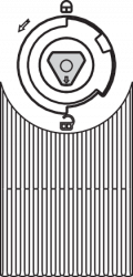
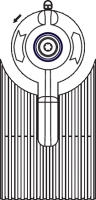
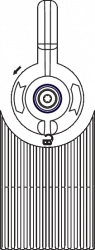
- The actuating curves show the typical detection range of the actuator depending on the actuating direction.
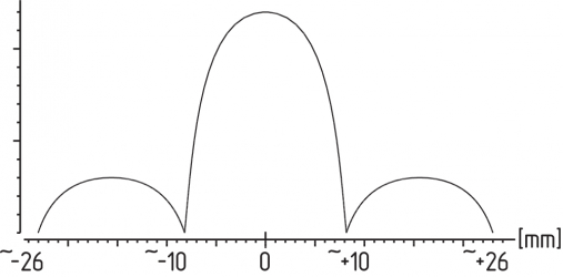 | 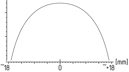 |
 | 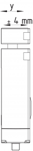 |
- The approach direction must only be from the X and Y directions.
- The maximum distance of 7 mm between the actuator and the solenoid interlock must be maintained so that the stipulated holding force and the safe clamping function is achieved according to SIL 3. The construction of the guard door is to be designed so that it is not possible to move the guard system with the actuator on the Z axis so far that the distance between the interlock and the actuator is greater than 7 mm.
- The safety equipment must be designed so that there is no crushing hazard due to the movement of the bolt.
Mounting of the actuators
Refer to the mounting instructions manual for the corresponding actuator.
To avoid any interference inherent to this kind of system and any reduction of the switching distances, please observe the following guidelines:
- Metal parts and magnetic fields in the area of the solenoid interlock and the actuator can influence the switch distance or lead to malfunctions
- Keep away from metal chips
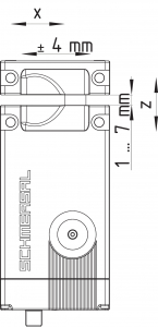
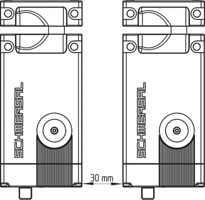
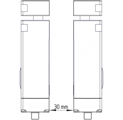
Minimum distance between two solenoid interlocks
as well as other systems with same frequency (125 kHz): 30 mm
 |  |
3.2 Manual release
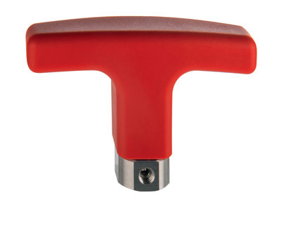
For the machine set-up, the solenoid interlock can be unlocked in a de-energised condition. Turning the triangle of the manual release using the triangular key to the q position releases the solenoid interlock. The normal locking function is only restored after the manual release has been returned to its original position p.
Triangular key TK-M5 (101100887) available as accessory.
- Structurally, after turning back the mechanical release a mechanical release that is still active can be indicated by the LEDs (all three LEDs flash). These will be reset after the control inputs are driven again.
- Do not turn the manual release beyond the end stop.
| Locked position | Unlocked position |
|---|---|
 |  |
3.3 Electrical manual release - E (for -ST2)
The electrical manual release can be achieved with an additional auxiliary power supply. The auxiliary power supply unit H1 is for this purpose.
The AZM400 should only be supplied with the auxiliary power supply, this is so the locking bolt can be released independently of the control inputs.
Then no other actions are required, the safety and diagnostic units remain off.
System condition (only valid during the initialising phase):
| Main supply | Auxiliary supply | System condition |
|---|---|---|
| 0 V | 0 V | Locking bolt remains in position (safety outputs switched off) |
| 24 V | 0 V | dependent on the control inputs |
| 0 V | 24 V | Locking bolt is retracted automatically (unlock) |
| 24 V | 24 V | Locking bolt remains in position (fault) |
- The wiring and actuation of the electrical manual release is to undergo a technical safety validation. The signal from the auxiliary power supply via UPS is then processed differently and internally so that short-circuits can be detected.
3.4 Emergency exit -T
Emergency exit for use within the hazardous area.
To activate the emergency exit, turn the red lever in the direction of the arrow to the end stop. The bolt moves due to spring force to the unlocked position so that the guard system can be opened in this position and the safety outputs switch off. In the unlocked position, the guard system is secured against unintentional locking.
- Do not turn beyond the end stop.
| Locked position | Unlocked position |
|---|---|
 |  |
- To ensure correct operation of emergency exit -T the safety door/guard must not be in a mechanically tensioned state.
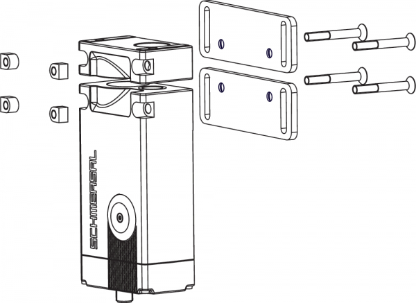
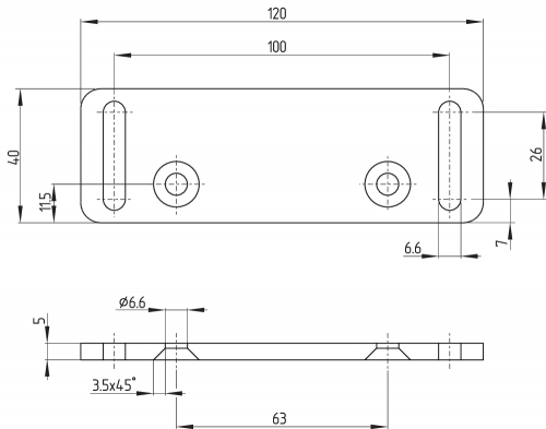
3.5 Assembly with mounting set
When using 40 mm aluminium profile, the optimum mounting set MS-AZM400 can be used. This consists of two mounting plates including four bolt and four nuts.
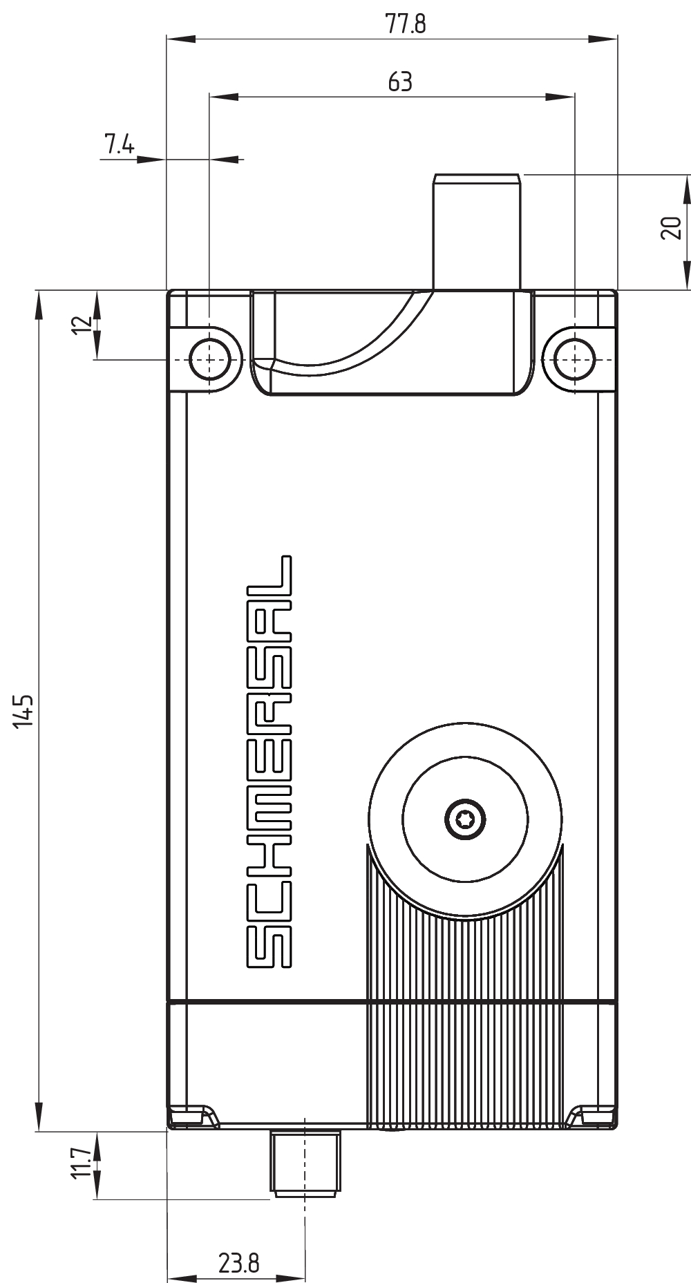
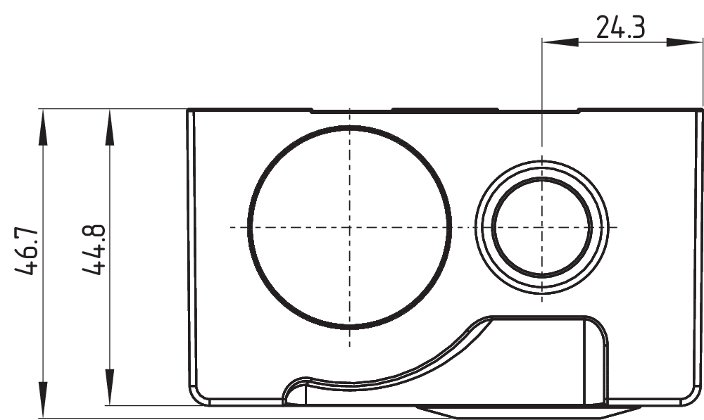
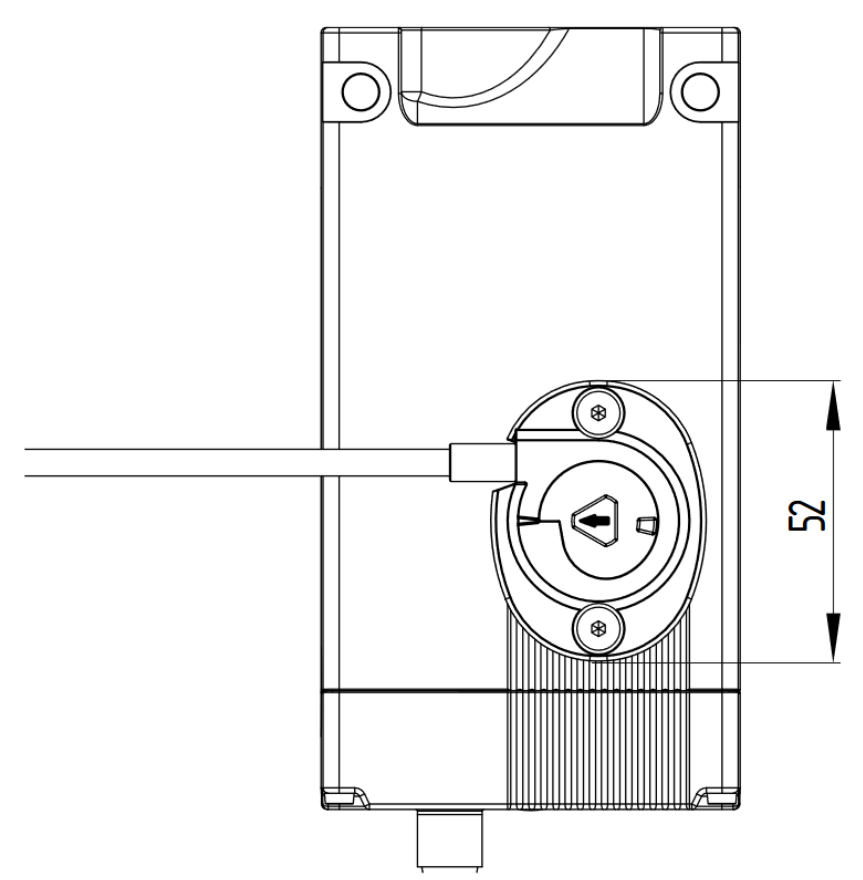
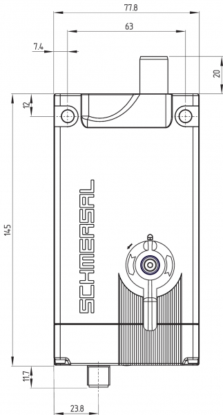
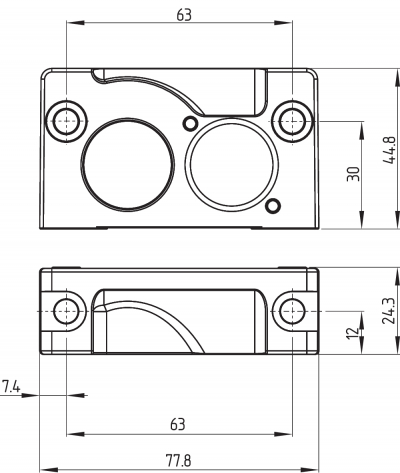
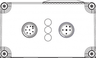
3.6 Dimensions
All measurements in mm.


AZM400 with emergency exit
| AZM400Z-ST..-T | AZM400Z-ST2..-T |
|---|---|
 | 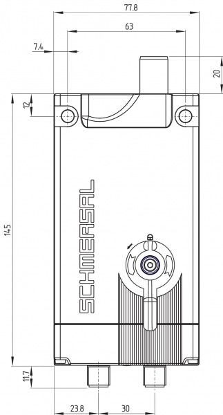 |
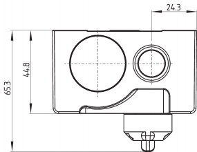 |
| Key | |
|---|---|
| A1 | Manual release with cover |
| A2 | Emergency Exit |
| B | Locking bolt (extended) |
| C1 | Connector plug M12, 8-pole |
| C2 | Connector plug M12, 5-pole |
| D | RFID Sensor |
3.7 Actuator and accessories
Actuator AZM400-B1 (not included in delivery)
Mounting plate, part of the mounting set MS-AZM400
(available as accessory)
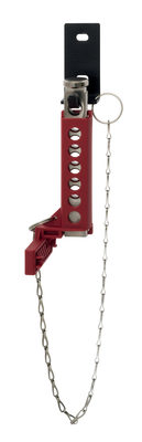
Lockout tag SZ400
(available as accessory)
For detailed information and assembly instructions, see operating instructions SZ400
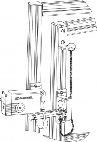
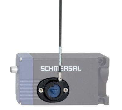
Bowden cable release ACC-AZM400-BOW-.M-.M
(available as accessory)
Observe the additional notes in the operating instructions of the Bowden cable release.

4 Electrical connection
4.1 General information for electrical connection
- The electrical connection may only be carried out by authorised personnel in a de-energised condition.
The voltage inputs A1 (and H1 with the AZM400Z-ST2..), and the control inputs E1, E2 and E3 must have a permanent protection against over-voltage. The use of PELV supply units according to EN 60204-1 is recommended.
The safety outputs can be integrated into the safety circuit of the control system.
The required electrical cable fuse protection must be integrated in the installation.
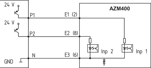
4.2 Control options in the normal operating mode
Due to the control inputs E1, E2 and E3 for controlling the guard locking function it is possible to use different control options to be able to drive the AZM400 with a different safety controller. The function of the control inputs is the same for both ST and ST2 versions. Setting the operational control inputs according to the following table causes the interlock to unlock.
| Input condition | Version P/P | Version P/N | |||
|---|---|---|---|---|---|
| E1 | E2 | E3 | E1 = E2 | E3 | |
| Lock | open | open | GND | open | open |
| Unlock | 24 V | 24 V | GND | 24 V | GND |
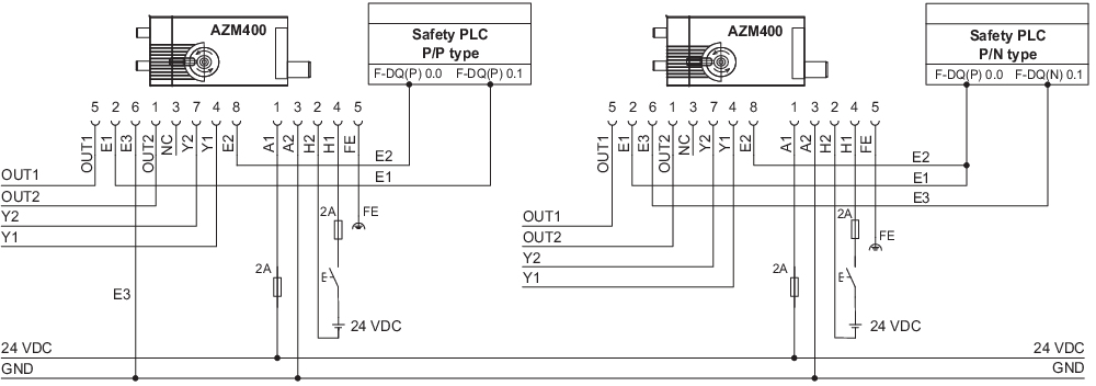
Use of safety outputs of the type P/P:
safety controller
Use of safety controls of the type P/N:
safety controller

- The outputs used for the control must correspond to the Performance Level (PL) of the guard system. To achieve the PL e the control must have tested outputs as these are not tested by the AZM400.
- Independent of the version used, the notes in the Operating Instructions of the used controller should be observed.
These could include:
- Shielded installed cable
- Minimum interval every 24 hours
- etc.
Block drive
If the locking bolt does not reach the "locked" condition with the first attempt, the AZM400 makes an autonomous attempt. If the second attempt also fails, the AZM400 signals a fault (comp. table 2).
After a malfunction, condition of the control inputs has to be changed to allow the locking bolt to be driven out again.
When the guard system closes slowly, a block drive can occur if the actuator that is opening is not in front of the bolt being driven out (see Chapter "Operating equipment and distances").
Unlocking after Power On
If after switching on, the AZM400 is already in the locked position, the device must first be unlocked and then locked again. This is to verify the causality of the drive signals and to check the sufficient depth of the locking bolt. The yellow LED flashes after power-on in the locked position.
4.3 Requirements for the connected safety-monitoring module
Dual-channel safety input, suitable for 2 p-type semi-conductor outputs (OSSD)
The solenoid interlock cyclically switch off the safety output to test them. The safety-monitoring module therefore does not need to be equipped with a cross-wire short detection. The test impulse time of ≤ 0.4 ms must be tolerated by the evaluation. The test impulse, the switch-off time of the solenoid interlock can be extended depending on the cable length and the capacity of the cable used.
- Safety controller configuration
If the solenoid interlock is connected to electronic safety-monitoring modules, we recommend that you set a discrepancy time of 100 ms. The safety inputs of the safety-monitoring module must be able to blank a test impulse of < 1 ms.
- Information for the selection of suitable safety-monitoring modules can be found in the Schmersal catalogues or in the online catalogue on the Internet: products.schmersal.com
4.4 Wiring configuration and connector accessories
Pin assignment of the version AZM400Z-ST-…
| Function safety switchgear | Pin configuration of the connector M12. 8-pole | Colour codes of the Schmersal connector plugs to DIN 47100 | Possible colour code of other commercially available connector plugs according to EN 60947-5-2 | |
|---|---|---|---|---|
 | ||||
| A1 | UB | 1 | WH | BN |
| E1 | Control input 1 | 2 | BN | WH |
| A2 | GND | 3 | GN | BU |
| Y1 | Safety output 1 | 4 | YE | BK |
| OUT | Diagnostic output | 5 | GY | GY |
| E3 | Control input 3 | 6 | PK | PK |
| Y2 | Safety output 2 | 7 | BU | VT |
| E2 | Control input 2 | 8 | RD | OR |
Pin assignment of the version AZM400Z-ST2-…
| Function safety switchgear | Pin configuration of the connector M12, 8-pole | Colour codes of the Schmersal connector plugs to DIN 47100 | Possible colour code of other commercially available connector plugs according to EN 60947-5-2 | |
|---|---|---|---|---|
| ||||
| OUT2 | Diagnostic output 2 | 1 | WH | BN |
| E1 | Control input 1 | 2 | BN | WH |
| - | (Not connected) | 3 | GN | BU |
| Y1 | Safety output 1 | 4 | YE | BK |
| OUT1 | Diagnostic output 1 | 5 | GY | GY |
| E3 | Control input 3 | 6 | PK | PK |
| Y2 | Safety output 2 | 7 | BU | VT |
| E2 | Control input 2 | 8 | RD | OR |
| Function safety switchgear | Pin configuration of the connector M12, 5-pole | Colour codes of the Schmersal connector plugs to DIN 47100 | Possible colour code of other commercially available connector plugs according to EN 60947-5-2 | |
|---|---|---|---|---|
 | ||||
| A1 | UB | 1 | BN | WH |
| H2 | E | 2 | WH | BN |
| A2 | GND | 3 | BU | GN |
| H1 | Uhe | 4 | BK | YE |
| FE | Functional earth connection 3 | 5 | GY | GY |
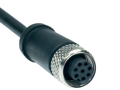
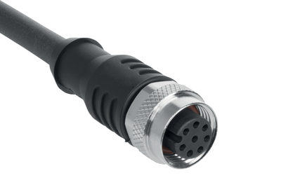
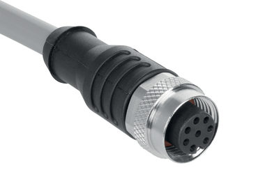
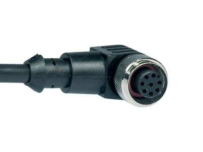
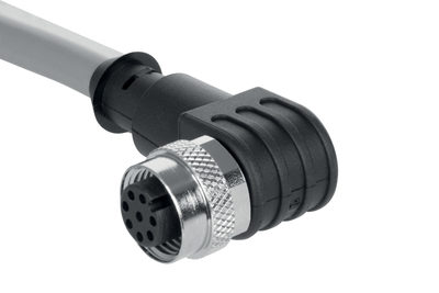
Accessories Pre-wired cables
| Pre-wired cables with socket (female) M12, 8-pole - 8 x 0.25 mm², IP67 / IP69 | |
|---|---|
| Cable length | Ordering code |
| 2.5 m | 103011415 |
| 5.0 m | 103007358 |
| 10.0 m | 103007359 |
| 15.0 m | 103011414 |
| Pre-wired cables with socket (female) M12, 5-pole - 5 x 0.34 mm² | |
|---|---|
| Cable length | Ordering code |
| 5.0 m | 103010816 |
| 10.0 m | 103010818 |
Further versions in other lengths and with angled cable exit are available upon request.
4.5 Wiring examples
The application examples shown are suggestions. They however do not release the user from carefully checking whether the switchgear and its set-up are suitable for the individual application. The application examples shown are suggestions.
Wiring example 1: AZM400Z-ST

| Key, wiring | |
|---|---|
| Connector plug M12, 8-pole | |
| A1 | UB |
| A2 | GND |
| E1 | Control input 1 |
| E2 | Control input 1 |
| E3 | Control input 2 |
| Y1 | Safety output 1 |
| Y2 | Safety output 2 |
| OUT | Diagnostic output |
Wiring example 2: AZM400Z-ST2
| Key, wiring | |||
|---|---|---|---|
| Connector plug M12, 8-pole | Connector plug M12, 5-pole | ||
| E1 | Control input 1 | A1 | UB |
| E2 | Control input 2 | A2 | GND |
| E3 | Control input 3 | H1 | Uhe |
| Y1 | Safety output 1 | H2 | E |
| Y2 | Safety output 2 | FE | Functional earth connection |
| OUT1 | Diagnostic output 1 | ||
| OUT2 | Diagnostic output 2 | ||
5 Actuator teaching / actuator detection
Solenoid interlocks with standard coding are ready to use upon delivery.
Individually coded solenoid interlocks and actuators will require the following "teach-in" procedure:
- Switch the solenoid interlock's voltage supply off and back on.
- Introduce the actuator in the detection range. The teach-in procedure is signalled at the solenoid interlock, green LED off, red LED on, yellow LED flashes (1 Hz).
- After 10 seconds, brief yellow cyclic flashes (3 Hz) request the switch-off of the operating voltage of the solenoid interlock. (If the voltage is not switched off within 5 minutes, the solenoid interlock cancels the "teach-in" procedure and signals a false actuator by 5 red flashes.)
- Once the operating voltage is switched back on, the actuator must be detected once more in order to activate the actuator code that has been taught in. In this way, the activated code is definitively saved!
For ordering suffix -I1, the executed allocation of safety switchgear and actuator is irreversible.
For ordering suffix -I2, the "teach-in" procedure for a new actuator can be repeated an unlimited number of times. When a new actuator is taught, the code, which was applicable until that moment, becomes invalid. Subsequent to that, an enabling inhibit will be active for ten minutes, thus providing for an increased protection against tampering. The green LED will flash until the expiration of the time of the enabling inhibit and the detection of the new actuator. In case of power failure during the lapse of time, the 10-minutes tampering protection time will restart.
- Make organisational measures against possible manipulation with other actuators in case that a standard coded variant is used.
6 Active principle and diagnostic functions
6.1 Mode of operation of the safety outputs
With the solenoid interlock AZM400, the unlock signals immediately switch off the safety outputs. The unlocked guard system can be locked again as long as the actuator is within the detection range of the solenoid interlock. In that case, the safety outputs are re-enabled.
If the safety outputs are already enabled, any error that does not immediately affect the functionality of the solenoid interlock (e.g. too high an ambient temperature, interference potential at the safety outputs, cross-wire short) will lead to a warning message, the disabling of the diagnostic output OUT of the ST version and OUT2 of the ST2 version and the delayed shutdown of the safety outputs. safety outputs are disabled if the error warning is active for 30 minutes. The signal combination, diagnostic output OUT of the ST version and OUT2 of the ST2 version disabled and safety channels still enabled, can be used to stop the production process in a controlled manner. After rectifying the fault, the fault message is acknowledged by opening and closing the associated safety door or by switching the operating voltage off and on again.
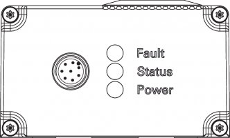
6.2 Diagnostic-LEDs
The solenoid interlock signals the operating condition, as well as errors through 3-colour LEDs.
| green (Power) | Supply voltage on |
| yellow (Status) | Operating condition |
| red (Fault) | Error (see table 2: Error messages / flash codes red diagnostic LED) |
| Arrangement of the LEDs | |
|---|---|
 |  |
6.3 Diagnostic outputs
The short-circuit proof diagnostic output OUT or OUT1 and OUT2 of the ST2 version can be used for central visualisation or control functions, e.g. in a PLC. I It indicates the switching condition as shown in the table 1.
The diagnostic outputs OUT or OUT1 and OUT2 are not safety relevant outputs.
Error
Errors, which no longer guarantee the safe function of the solenoid interlock (internal errors) cause the safety outputs to be immediately disabled. Any error that does not immediately affect the safe functionality of the solenoid interlock (e.g. excess ambient temperature, safety output to external potential, short circuit) will lead to a delayed shut-down (refer to table 2). After the rectification of the error, the error message is reset by opening the corresponding safety guard.
Errors on the control inputs do not cause the shut-down of the safety outputs.
Error warning
A fault has occurred, which causes the safety outputs to be disabled after 30 minutes (LED "fault" flashes, see Table 2). The safety outputs initially remain enabled (max. 30 minutes). This enables the shutdown of the process in a controlled manner. An error warning is deleted when the cause of error is eliminated.
6.4 Diagnostic information
| Table 1: Diagnostic information of the solenoid interlock AZM400 | ||||||||
|---|---|---|---|---|---|---|---|---|
| System condition | Control signals | LED | Safety outputs | Diagnostic outputs | ||||
| Guard locking function | green | red | yellow | Y1, Y2 | ST version OUT | ST2 version OUT1 | ST2 version OUT2 | |
| Door open and unlocked (bolt retracted) | Unlock | On | Off | Off | 0 V | 0 V | 0 V | 0 V |
| Door closed and unlocked (bolt retracted) | Unlock | On | Off | Flashes | 0 V | 24 V | 0 V | 0 V |
| Door closed, lock action active (Bolt moving forwards) | Lock | On | Off | Flashes | 0 V | 0 V | 0 V | 24 V |
| Door closed and locked (Bolt extended) | Lock | On | Off | On | 24 V | 24 V | 24 V | 24 V |
| Door closed, unlocking action active (Bolt being retracted) | Unlock | On | Off | Flashes | 0 V | 0 V | 24 V | 24 V |
| Error states: | ||||||||
| Error warning 1) | Without meaning | On | Flashes 2) | On | 24 V | 0 V | 24 V | 0 V |
| Error | Without meaning | On | Flashes 2) | Off | 0 V | 0 V | 24 V | 0 V |
| Mechanical auxiliary release, emergency release or Bowden cable release active | Without meaning | Flashes | Flashes | Flashes | 0 V | 24 V | 0 V | 24 V |
| Electronic manual release active | Without meaning | Flashes | Flashes | Flashes | 0 V | - | 0 V | 0 V |
| Teaching the actuator at execution I1/I2: | ||||||||
| Teach-in procedure actuator started | Unlock | Off | On | Flashes slowly | 0 V | 0 V | 0 V | 0 V |
| Actuator teaching can be completed | Unlock | Off | On | Flashes quickly | 0 V | 0 V | 0 V | 0 V |
| Only I2: Actuator has been taught (Manipulation protection time is running) | Unlock | Flashes | Off | Off | 0 V | 24 V | 0 V | 24 V |
1) after 30 min. disabling due to fault 2) see flash code | ||||||||
| Table 2: Error messages / flash codes red diagnostic LED | |||
|---|---|---|---|
| Flash codes (red) | Designation | Autonomous switch-off after | Error cause |
| 1 flash pulse | Error (warning) at output Y1 | 30 min | Fault in output test or voltage at output Y1, although the output is disabled. |
| 2 flash pulses | Error (warning) at output Y2 | 30 min | Fault in output test or voltage at output Y2, although the output is disabled. |
| 3 flash pulses | Error (warning) cross-wire short | 30 min | Cross-wire short between the output cables or fault at both outputs |
| 4 flash pulses | Error (warning) temperature too high | 30 min | The temperature measurement reveals an internal temperature that is too high |
| 5 flash pulses | Actuator fault | 0 min | Incorrect or defective actuator |
| 6 flash pulses | Error control inputs / electronic manual release | - | Invalid input condition of the control inputs and/or of the electronic manual release |
| 7 flash pulses | Fault with the actuator detection | 0 min | Distance between the AZM400 and the actuator is too large; external magnetic fields prevent detection |
| 8 flash pulses | Fault Block drive | 0 min | Actuator not properly aligned for the solenoid interlock |
| 9 flash pulses | Fault over/under voltage | 0 min | Supply voltage outside specification |
| Continuous red | Internal error | 0 min | Device defective |
| Table 2.1: Error messages / flash codes yellow LED | |||
|---|---|---|---|
| Flash codes (yellow) | Designation | Autonomous switch-off after | Error cause |
| Fast yellow flashing (2 Hz) | Error control inputs | 0 min | Frequency too high (> 0.3 Hz) at control inputs E1 and E2 |
7 Set-up and maintenance
7.1 Functional testing
The safety function of the safety components must be tested. The following conditions must be previously checked and met:
- Check max. axial misalignment of actuator and solenoid interlock.
- Check max. angle displacement.
- Make sure that it is not possible to lift the actuator in the Z axis above the extended bolt.
- • Check for a secure installation of the actuator and the solenoid interlock
- Fitting and integrity of the cable connections.
- Check the switch enclosure for damages
- Remove particles of dust and soiling.
- For versions with emergency exit, the following should also be considered:
It should be possible to open the guard system from within the hazardous area; it should not be possible to lock the safety guard from inside.
7.2 Maintenance
In the case of correct installation and intended use, the safety switchgear is maintenance-free.
A regular visual inspection and functional test, including the following steps, is recommended:
- • Check for a secure installation of the actuator and the solenoid interlock
- Check max. axial misalignment of actuator and solenoid interlock.
- Check max. angle displacement.
- Make sure that it is not possible to lift the actuator in the Z axis above the extended bolt.
- Fitting and integrity of the cable connections.
- Check the switch enclosure for damages
- Remove particles of dust and soiling.
- Adequate measures must be taken to ensure protection against tampering either to prevent tampering of the safety guard, for instance by means of replacement actuators.
- Damaged or defective components must be replaced.
8 Disassembly and disposal
8.1 Disassembly
The safety switchgear must be disassembled in a de-energised condition only.
8.2 Disposal
- The safety switchgear must be disposed of in an appropriate manner in accordance with the national prescriptions and legislations.
| UK Declaration of Conformity |  |
| Company: | K.A. Schmersal GmbH & Co. KG Möddinghofe 30 42279 Wuppertal Germany Internet: www.schmersal.com |
| Declaration: | We hereby, under sole responsibility, certify that the hereafter described components both in their basic design and construction conform to the relevant statutory requirements, regulations and designated standards of the United Kingdom. |
| Name of the component: | AZM400 |
| Type: | See ordering code |
| Description of the component: | Interlocking device with safe locking function |
| Relevant legislation: | Supply of Machinery (Safety) Regulations | 2008 |
| Radio Equipment Regulations | 2017 | |
| The Restriction of the Use of Certain Hazardous Substances in Electrical and Electronic Equipment Regulations | 2012 |
| Designated standards: | EN 60947-5-3:2013 EN ISO 14119:2013 EN 300 330 V2.1.1:2017 EN ISO 13849-1:2015 IEC 61508 parts 1-7:2010 |
| Approved body for Type Examination: | TÜV Rheinland UK Ltd. 1011 Stratford Road Solihull, B90 4BN ID: 2571 |
| Type examination certificate: | 01/205U/5467.00/22 |
| UK-Importer / Person authorised for the compilation of the technical documentation: | Schmersal UK Ltd. Paul Kenney Unit 1, Sparrowhawk Close Enigma Business Park Malvern, Worcestershire, WR14 1GL |
| Place and date of issue: | Wuppertal, September 23, 2022 |
 |
| Authorised signature Philip Schmersal Managing Director |
| EU Declaration of Conformity | |
| Original | K.A. Schmersal GmbH & Co. KG Möddinghofe 30 42279 Wuppertal Germany Internet: www.schmersal.com |
| Declaration: | We hereby certify that the hereafter described components both in their basic design and construction conform to the applicable European Directives. |
| Name of the component: | AZM400 |
| Type: | See ordering code |
| Description of the component: | Interlocking device with safe locking function |
| Relevant Directives: | Machinery Directive | 2006/42/EC |
| RED-Directive | 2014/53/EU | |
| RoHS-Directive | 2011/65/EU |
| Applied standards: | EN 60947-5-3:2013 EN ISO 14119:2013 EN 300 330 V2.1.1:2017 EN ISO 13849-1:2015 IEC 61508 parts 1-7:2010 |
| Notified body for Type Examination: | TÜV Rheinland Industrie Service GmbH Am Grauen Stein, 51105 Köln ID n°: 0035 |
| EC-Type Examination Certificate: | 01/205/5467.01/20 |
| Person authorised for the compilation of the technical documentation: | Oliver Wacker Möddinghofe 30 42279 Wuppertal |
| Place and date of issue: | Wuppertal, August 14, 2020 |
|
| Authorised signature Philip Schmersal Managing Director |
Schmersal, Inc., 115 E Stevens Ave, Suite 208, Valhalla, NY 10595
The details and data referred to have been carefully checked. Images may diverge from original. Further technical data can be found in the manual. Technical amendments and errors possible.
Generated on: 5/12/2025, 7:37 PM