SFB-PN-IRT-8M12-IOP-V2
SFB-PN-IRT-8M12-IOP-V2
- Safety fieldbox for PROFINET/PROFIsafe
- For connection of up to 8 safety switching devices
- Integrated dual-port switch, IRT-capable
- Protection class IP67
Ordering data
| Product type description |
SFB-PN-IRT-8M12-IOP-V2 |
| Article number (order number) |
103040357 |
| EAN (European Article Number) |
4030661561554 |
| eCl@ss number, version 12.0 |
27-24-26-04 |
| eCl@ss number, version 11.0 |
27-24-26-04 |
| eCl@ss number, version 9.0 |
27-24-26-04 |
| ETIM number, version 7.0 |
EC001599 |
| ETIM number, version 6.0 |
EC001599 |
Approvals - Standards
| Certificates |
TÜV cULus UKCA |
General data
| Standards |
EN IEC 61131-1 EN IEC 61131-2 EN ISO 13849-1 EN IEC 60947-5-3 EN IEC 61508 |
| Housing material |
Thermoplastic, Polyamide PA 6 GF |
| Material of the identification label |
Plastic, Polyamide PA |
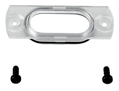
| Material of viewing window |
Polyamide PACM 12 |
| Material of electronic encapsulation |
Polyurethane 2K PU |
| Gross weight |
655 g |
General data - Features
| Integral system diagnostics, general |
Yes |
| Safety classification |
| Standards |
EN ISO 13849-1 EN IEC 61508 |
| Safety classification - Safety inputs 2-channels |
| Performance Level, up to |
e |
| Category |
4 |
| Diagnostic Coverage (DC) Level |
99 % |
| PFH value |
1.10 x 10⁻⁹ /h |
| PFDavg |
9.60 x 10⁻⁵ |
| Safety Integrity Level (SIL), suitable for applications in |
3 |
| Mission time |
20 Year(s) |
| Response time of local safety input ⇒ Fieldbus, maximum |
20 ms |
| Notice |
The SFB fulfils the requirements as PDDB (proximity switch with defined behaviour under fault conditions) according to EN 60947-5-3 in combination with magnetic sensors (2 NC contacts) up to PL e / SIL 3. |
| Safety classification - Safety inputs 1-channel |
| Performance Level, up to |
d |
| Category |
2 |
| Diagnostic Coverage (DC) Level |
90 % |
| PFH value |
2.30 x 10⁻⁷ /h |
| PFDavg |
2.00 x 10⁻² |
| Safety Integrity Level (SIL), suitable for applications in |
1 |
| Mission time |
20 Year(s) |
| Response time of local safety input > Fieldbus, maximum |
20 ms |
| Test interval for error detection |
10 s |
| Safety classification - Safety outputs 1-channel |
| Performance Level, up to |
d |
| Category |
3 |
| Diagnostic Coverage (DC) Level |
90 % |
| PFH value |
1.00 x 10⁻⁷ /h |
| PFDavg |
8.80 x 10⁻³ |
| Safety Integrity Level (SIL), suitable for applications in |
2 |
| Mission time |
20 Year(s) |
| Reaction time Fieldbus > local safety output |
50 ms |
| Safety classification - Safety outputs 2-channels |
| Performance Level, up to |
e |
| Category |
4 |
| Diagnostic Coverage (DC) Level |
99 % |
| PFH value |
1.20 x 10⁻⁹ /h |
| PFDavg |
1.10 x 10⁻⁴ |
| Safety Integrity Level (SIL), suitable for applications in |
3 |
| Notes (Safety Integrity Level) |
This product must only be replaced in the application by an identical product of type SFB-PN-IRT-8M12-IOP-V2 with part no. 103040357. The older product version has a lower safety level. |
| Mission time |
20 Year(s) |
| Reaction time Fieldbus > local safety output |
50 ms |
Mechanical data
| Mounting |
Screws |
| Type of the fixing screws |
2x M6 |
| Tightening torque of the fixing screws, maximum |
3 Nm |
| Type of the fixing screws, viewing window |
2x TX10 (Torx) |
| Tightening torque of the fastening screws for the viewing window, maximum |
0.6 Nm |
Mechanical data - Connection technique
| Termination |
M12 Connector socket/connector |
| Terminal connector, Input/Output |
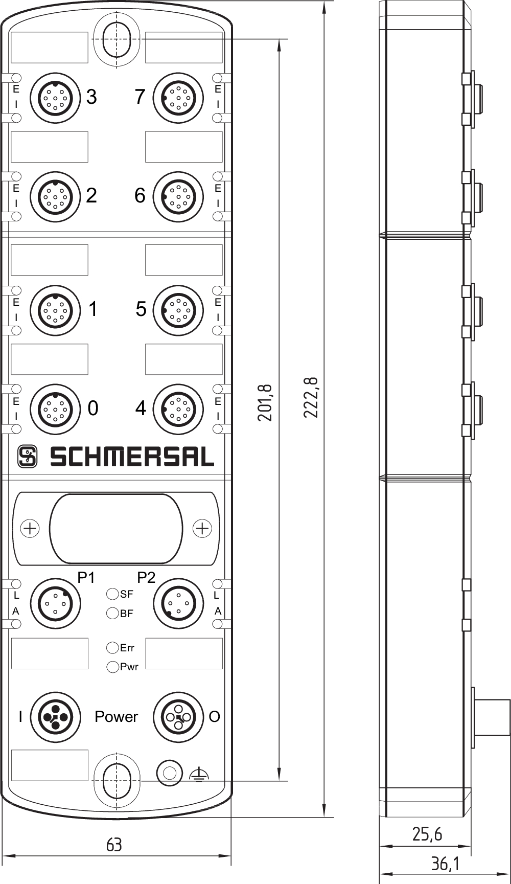
X0 - X7: M12, 8-pole, A-coded |
| Terminal Connector, Power I/O |
M12 POWER, 4-pole, T-coded |
| Terminal Connector, Field bus |
M12, 4-pole, D-coded |
| Tightening torque of electrical connection, minimum |
0.8 Nm |
| Tightening torque of electrical connection, maximum |
1.5 Nm |
Mechanical data - Dimensions
| Length |
222.8 mm |
| Width |
63 mm |
| Height |
36.1 mm |
Ambient conditions
| Degree of protection |
IP66 IP67 |
| Ambient temperature |
-25 ... +55 °C |
| Storage and transport temperature |
-25 ... +70 °C |
| Relative humidity, minimum |
10 % |
| Relative humidity, maximum |
95 % |
| Note (Relative humidity) |
non-condensing |
| Resistance to vibrations |
10 … 150 Hz, amplitude 0.35 mm / 5 g |
| Restistance to shock |
30 g / 11 ms |
| Protection class |
III |
| Permissible installation altitude above sea level, maximum |
2,000 m |
Ambient conditions - Insulation values
| Rated insulation voltage Ui |
32 VDC |
| Rated impulse withstand voltage Uimp |
0.8 kV |
| Overvoltage category |
III |
| Degree of pollution |
3 |
Electrical data
| Operating voltage |
24 VDC -15 % / +10 % (stabilised PELV power supply) |
| Current consumption |
200 mA |
| Rated operating voltage |
24 VDC |
| Operating current |
10,000 mA |
| Note (Electrical data, Fuse rating) |
External fuse protection required ≤ 10A slow blow when used to UL 61010. |
| Time to readiness, maximum |
8,000 ms |
| Device Watchdog Time |
10 ms |
| Device Acknowledgement Time, maximum |
25 ms |
| Reaction Time Safety Input, maximum |
20 ms |
| Reaction Time Safety Output, maximum |
50 ms |
Electrical data - Communication protocols
| Feldbus Protokoll |
PROFINET / PROFIsafe |
| Fieldbus specification |
V2.3, Conformance Class C |
| Specification safety fieldbus |
V2.4 |
| Fieldbus properties |
Media Redundancy Protocol (MRP) Fast Start Up |
| Fieldbus network load class |
3 |
| Transfer rate |
100 Mbit/s Full Duplex |
| Adressing |
Discovery and Configuration Protocol (DCP) |
| Integrated switch |
Dual Port, 100 Mbit/s, IRT fähig |
| Fieldbus services |
I&M0 ... I&M3, SNMP, LLDP |
| Service interface |
WEB-Interface HTTP |
Electrical data - Device Ports
| Bezeichnung, Geräteanschlüsse |
X0 ... X7 |
| Cable length, device port |
30 m |
Electrical data - Power supply external devices
| Designation, Power supply |
A1 and A2 |
| Rated operating voltage |
24 VDC |
| Rated operating current |
800 mA |
| Internal electrical fuse |
1.5 A (Integrated automatic resettable fuse) |
Electrical data - Safety digital inputs
| Designation, Safety inputs |
X1 and X2 |
| Switching thresholds |
−3 V … 5 V (Low) 13 V ... 30 V (High) |
| Current consumption at 24 V |
6 mA |
| Permissible residual drive current |
1 mA |
| Test pulse duration, minimum |
0.01 ms |
| Test pulse duration, maximum |
1 ms |
| Test pulse interval, minimum |
20 ms |
| Test pulse interval, maximum |
120,000 ms |
| Classification ZVEI CB24I, Sink |
C1 |
| Classification ZVEI CB24I, Source |
C1 C2 C3 |
Electrical data - Safety digital outputs
| Designation, Safety outputs |
DO |
| Design of control elements |
short-circuit proof, p-type |
| Voltage drop Ud, maximum |
2 V |
| Leakage current Ir, maximum |
0.5 mA |
| Voltage, Utilisation category DC-12 |
24 VDC |
| Current, Utilisation category DC-12 |
0.8 A |
| Voltage, Utilisation category DC-13 |
24 VDC |
| Current, Utilisation category DC-13 |
0.8 A |
| Note, Utilisation category DC-13 |
Inductive load, maximum 400 mH |
| Switching frequency, maximum |
1 Hz |
| Test pulse duration, maximum |
1 ms |
| Test pulse interval, minimum |
15 ms |
| Test pulse interval, maximum |
500 ms |
| Classification ZVEI CB24I, Source |
C1 |
| Classification ZVEI CB24I, Sink |
C1 |
Electrical data - Diagnostic inputs / FB-Interface
| Designation, Diagnostic inputs / FB-Interface |
DI |
| Switching thresholds |
−3 V … 5 V (Low) 15 V … 30 V (High) |
| Current consumption at 24V |
12 mA |
| Input debounce filter |
10 ms |
| Data transfer rate FB-Interface |
19,2 kBaud |
Electrical data - Test pulse output
| Designation, Test pulse outputs |
Y1 and Y2 |
| Design of control elements |
short-circuit proof, p-type |
| Voltage drop Ud, maximum |
1 V |
| Current leakage Ir, maximum |
0.5 mA |
| Voltage, Utilisation category DC-12 |
24 VDC |
| Y1 rated current at 24 V |
15 mA |
| Y2 rated current at 24 V |
10 mA |
| Y2 rated current at 0 V |
30 mA |
| Test pulse interval, typical |
500 ms |
| Test pulse duration, maximum |
1 ms |
| Classification ZVEI CB24I, Sink |
C1 |
| Classification ZVEI CB24I, Source |
C1 |
LED status display - LED 01
| LED status |
Error LED device port |
| LED position |
E: 0 ... 7 |
| LED colour |
green/red |
LED status display - LED 02
| LED status |
Input LED device port |
| LED position |
I: 0 ... 7 |
| LED colour |
Yellow |
LED status display - LED 03
| LED status |
LED Link Ethernet port |
| LED position |
L: P1 + P2 |
| LED colour |
Green |
LED status display - LED 04
| LED status |
LED Activity Ethernet port |
| LED position |
A: P1 + P2 |
| LED colour |
Yellow |
LED status display - LED 05
| LED status |
System fault LED |
| LED position |
"SF": Module |
| LED colour |
green/red |
LED status display - LED 06
| LED status |
BUS fault LED |
| LED position |
"BF": Module |
| LED colour |
Red |
LED status display - LED 07
| LED status |
Fieldbox error LED |
| LED position |
"Err": Module |
| LED colour |
green/red |
LED status display - LED 08
| LED status |
Power-LED fieldbox |
| LED position |
"Pwr": Module |
| LED colour |
Green |
Other data
| Note (applications) |
Safe field box with decentralised I/Os |
Language filter
Datasheet
Operating instructions and Declaration of conformity
Getting Started
BG-test certificate
UL Certificate
UKCA certificate
Device description files
Configuration software (document with link)
Brochure
General information
SISTEMA-VDMA library
Download the latest version of Adobe Reader
Product picture (catalogue individual photo)
Dimensional drawing basic component
| EU Declaration of Conformity |  |
| Original | K.A. Schmersal GmbH & Co. KG Möddinghofe 30 42279 Wuppertal Germany Internet: www.schmersal.com |
| Declaration: | We hereby certify that the hereafter described components both in their basic design and construction conform to the applicable European Directives. |
| Name of the component: | SFB |
| Type: | See ordering code |
| Description of the component: | Safety fieldbox (IO module with fieldbox interface) |
| Relevant Directives: | Machinery Directive | 2006/42/EC |
| EMC-Directive | 2014/30/EU | |
| RoHS-Directive | 2011/65/EU |
| Applied standards: | EN 61131-2:2007 EN 60947-5-3:2013 EN ISO 13849-1:2015 IEC 61508 parts 1-7:2010 |
| Notified body for Type Examination: | TÜV Rheinland Industrie Service GmbH Am Grauen Stein, 51105 Köln ID n°: 0035 |
| EC-Type Examination Certificate: | 01/205/5878.00/22 |
| Person authorised for the compilation of the technical documentation: | Oliver Wacker Möddinghofe 30 42279 Wuppertal |
| Place and date of issue: | Wuppertal, May 4, 2022 |
 |
| Authorised signature Philip Schmersal Managing Director |
| UK Declaration of Conformity |  |
| Company: | K.A. Schmersal GmbH & Co. KG Möddinghofe 30 42279 Wuppertal Germany Internet: www.schmersal.com |
| Declaration: | We hereby, under sole responsibility, certify that the hereafter described components both in their basic design and construction conform to the relevant statutory requirements, regulations and designated standards of the United Kingdom. |
| Name of the component: | SFB-PN-IRT SFB-EIP |
| Type: | See ordering code |
| Description of the component: | Safety fieldbox (IO module with fieldbox interface) |
| Relevant legislation: | Supply of Machinery (Safety) Regulations | 2008 |
| Electromagnetic Compatibility Regulations | 2016 | |
| The Restriction of the Use of Certain Hazardous Substances in Electrical and Electronic Equipment Regulations | 2012 |
| Designated standards: | EN 61131-2:2007 EN 60947-5-3:2013 EN ISO 13849-1:2015 EN 61508 parts 1-7:2010 |
| Approved body for Type Examination: | TÜV Rheinland UK Ltd. 1011 Stratford Road Solihull, B90 4BN ID: 2571 |
| Type examination certificate: | 01/205U/5878.01/23 |
| UK-Importer / Person authorised for the compilation of the technical documentation: | Schmersal UK Ltd. Paul Kenney Unit 1, Sparrowhawk Close Enigma Business Park Malvern, Worcestershire, WR14 1GL |
| Place and date of issue: | Wuppertal, October 16, 2023 |
 |
| Authorised signature Philip Schmersal Managing Director |
Schmersal, Inc., 115 E Stevens Ave, Suite 208, Valhalla, NY 10595
The details and data referred to have been carefully checked. Images may diverge from original. Further technical data can be found in the manual. Technical amendments and errors possible.
Generated on: 9/11/2025, 12:36 AM
.png?id=e5ef4d56dad486103335c34b5b46f1ce)


